Introduction!
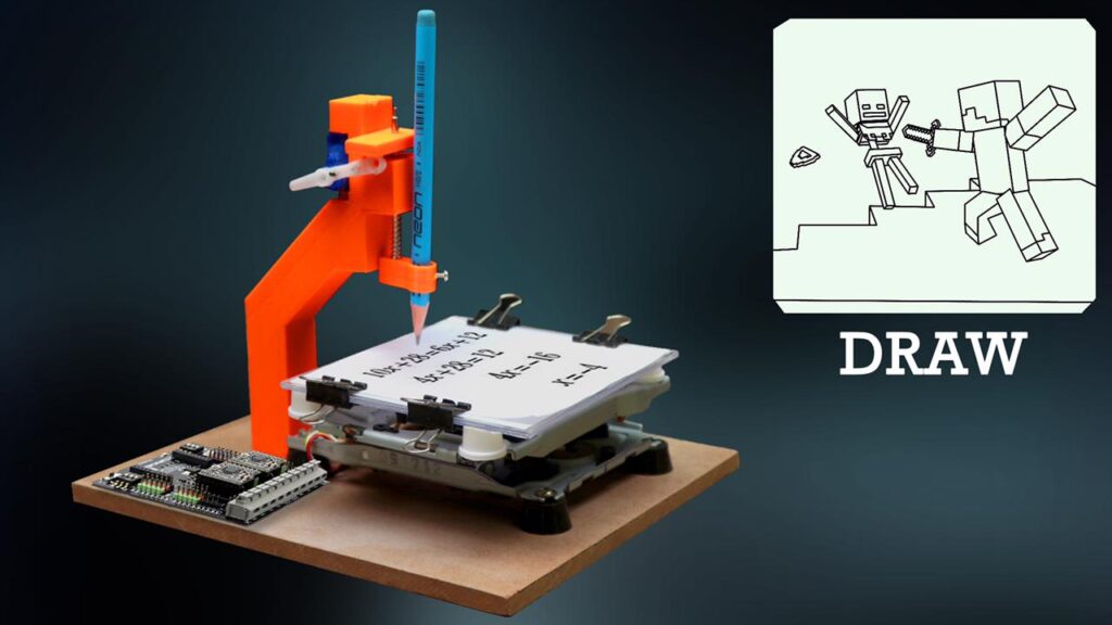
In this tutorial, I am going to show you how to make a 3D printed Mini CNC Machine which can be used for various tasks like drilling, milling and even lathe work. This machine is very easy to build and can be made in less than an hour. The best part about this machine is that it is very affordable and can be made with easily available parts. It is a prototype module, but once you build it you will definitely be able to build a very large CNC machine with much higher accuracy. The principle will be the same,
Don’t be afraid to build it, is very easy!!! This tutorial is also made for beginners!
Let’s get started!
————————————————————————-
Required Material – 3D Printed Mini CNC Machine
For this project you will need:
Part
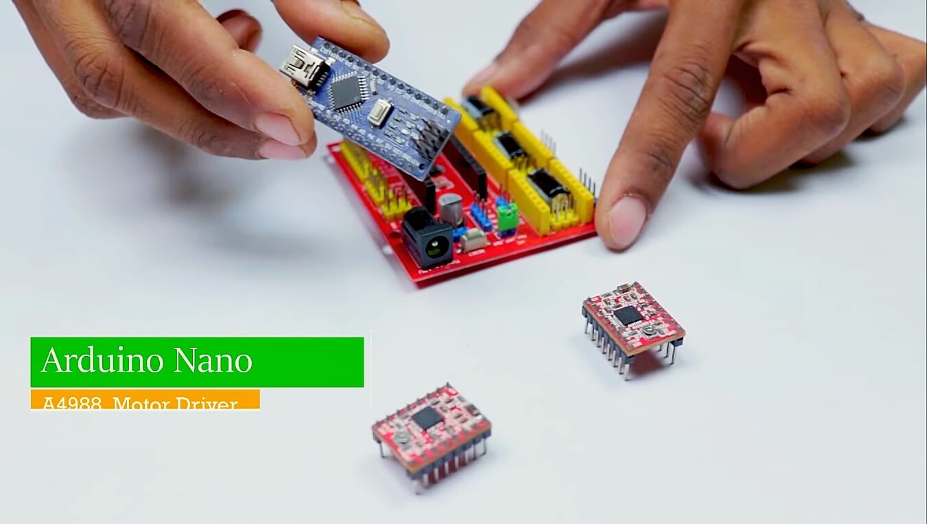
- Arduino Uno
- CNC Shield
- A4988 Motor Driver
- Mini Servo Motor
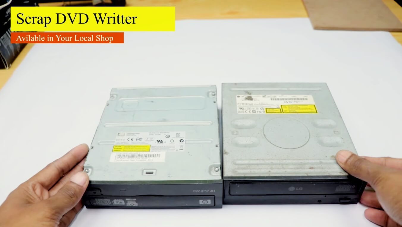
- 2x DVD/CD Drives
Tools
- Screwdriver
- Soldering iron
- Solder
- Cutting tool (e.g. Dremel) (Optional for cutting plastic parts)
- Glue
3D printed parts – They will need a 3D printer or order the printed parts from any website online.
https://www.thingiverse.com/thing:4788940
we will be walking through the steps on how to assemble your own Mini CNC Machine. This Mini CNC Machine is a great project for beginners and experts alike. With a simple design and easy-to-follow instructions, anyone can build their own Mini CNC Machine.
What is a CNC Writing Machine?
A CNC writing machine is a computer-controlled machine that is used to write text or numbers on a variety of materials. The machine is programmed to follow a path that is determined by the user and can be used to create intricate designs or simple text. The machine is often used in the manufacturing process to create labels or nameplates for products.
How does a CNC writing Machine work?
I would like to know how does a CNC Machine work? A CNC machine is a computer-controlled machine that can be used to cut and shape a variety of materials. The machine uses a cutting tool that is controlled by a computer to remove material from the workpiece. The computer controls the cutting tool to follow a path that is programmed into the computer.
CNC MAchine Axis MOVEMENTS
- X-axis – left to right
- Y-axis – front to back
- Z-axis – up and down
Dvd/cd Drive Stepper Motors
What is a Stepper motor?
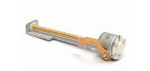
A stepper motor is a type of electric motor that converts electrical pulses into discrete mechanical movements. The motor’s position can then be controlled precisely, without any feedback mechanism. Stepper motors are used in a wide variety of applications, including 3D printers, CNC routers, and plotters.
- DVD/CD drive stepper motor specifications
It is challenging to find the exact specifications of these steppers. I found the specs of the DVD/CD stepper motor which is similar to mine on the internet. The important parameters are highlighted in orange.
| Motor type: | 2-phase 4-wire system |
| Step angel: | 18° |
| Voltage: | 5V |
| Resistance: | 14Ω |
| Phase: | 2 – 2 |
| Drive mode: | Bipolar |
| Max.starting frequency: | 900pps |
| Max.slew speed: | 1200pps |
| Holding torque: | 40 |
| Lead screw major diameter: | Φ3 |
| Lead screw lead pitch: | 3 |
| Size of motor outer diameter: | 15mm |
Typical Applications:
CD-ROM, POS machine, Laser equipment, Security devices, DVD VCR
Assembly
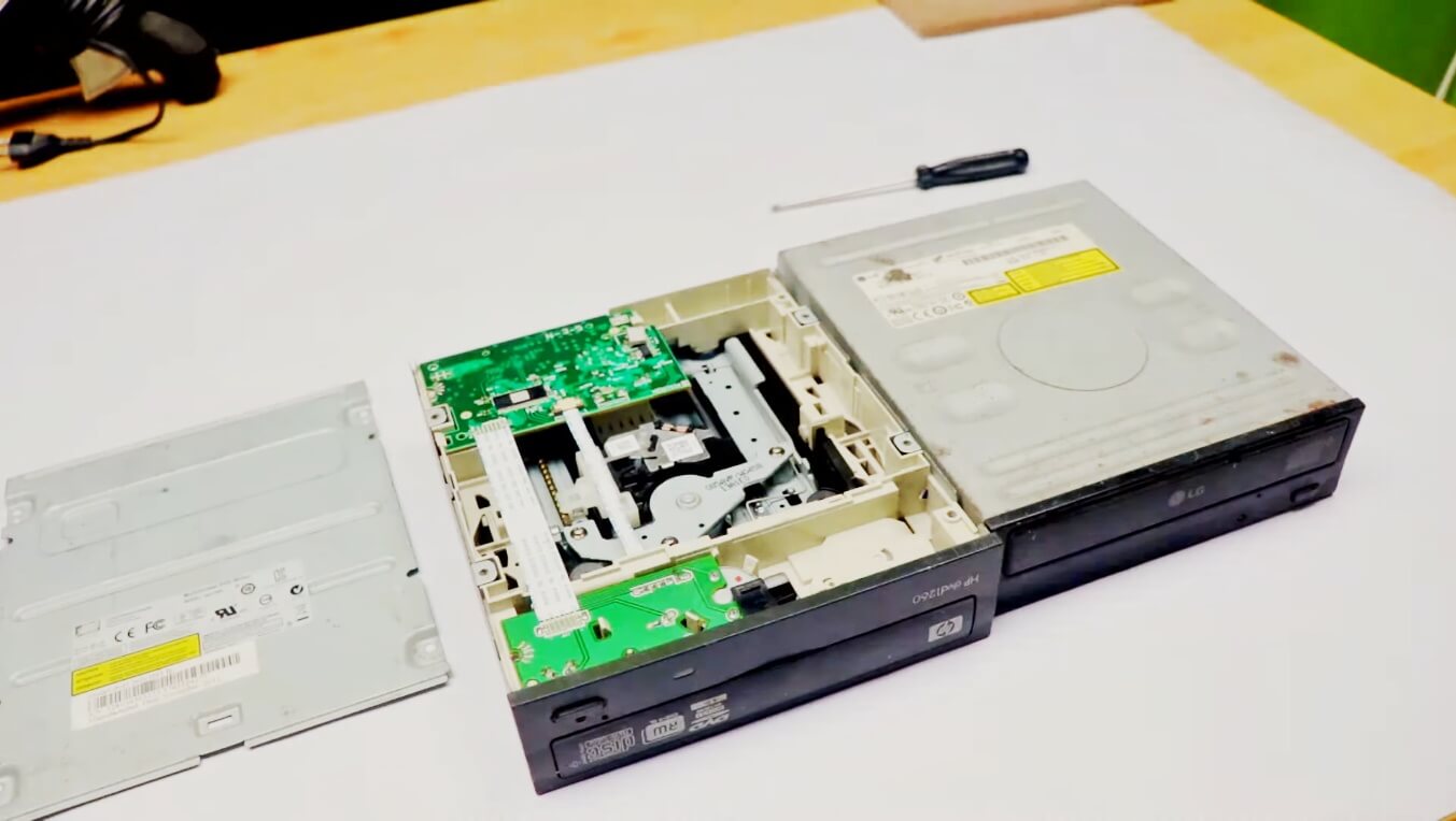
Disassembly DVD/CD Drives
Disassembling a DVD drive stepper motor is not a difficult task, but it does require some care and knowledge. The first step is to remove the DVD drive from its housing. Next, the stepper motor must be disengaged from the DVD drive head. This can be done by removing the four screws that hold it in place.
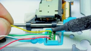
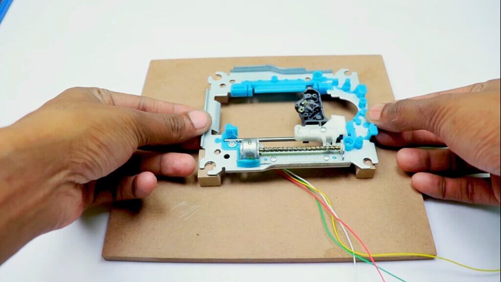
We soldered the wire with a stepper motor and then gave it a spacer with a piece of wood. (As shown in the picture below) we cut a wooden plate that will be our base.
Once the screws have been removed, the stepper motor can be carefully lifted out of the DVD drive head. With the motor removed, it is possible to access the internal components of the motor.
X-Axis and Y-Axis
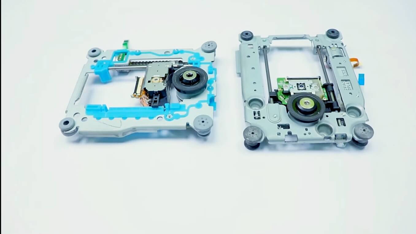
In the first image above you will see the Y axis of our CNC machine. Attach it to your surface, in this part you will need some screws and nuts.
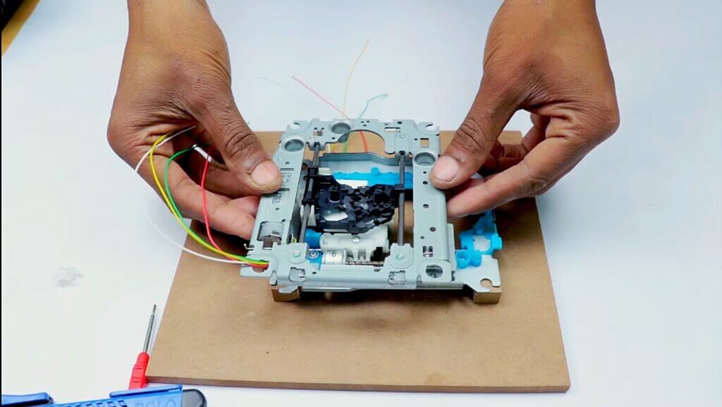
In the second image, you will see the X and Y axis. The X axis is attached to two plastic parts that I took from the remaining ‘garbage’ stuff.
This is an easy technique. Just make sure to put the Y axis straight to the CNC base and the X axis vertically in this (90 degrees).
The Z-Axis – Assemble the Pen Holder
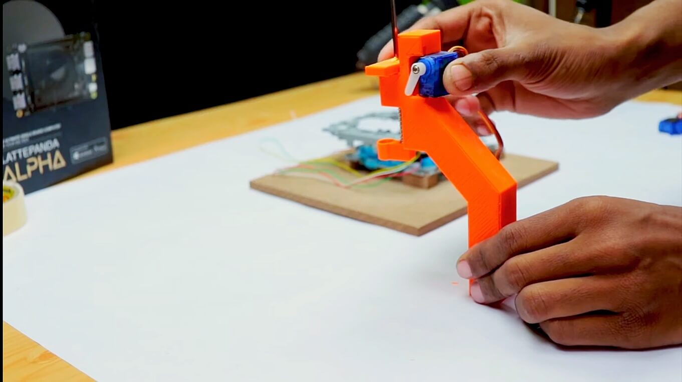
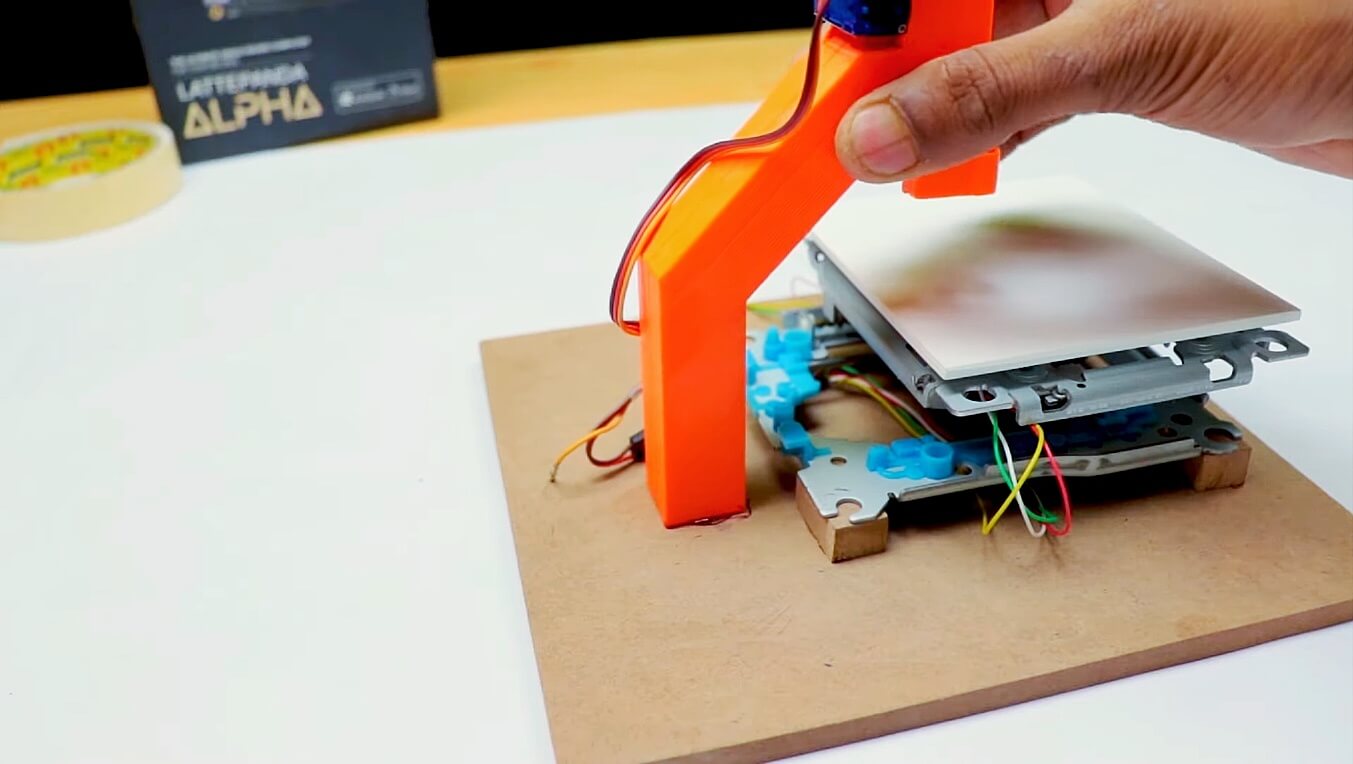
I have used 3D-printed pen holders. These are quite easy and fun. In the pen holder, I used a spring and a small road (which is in the DVD scraps) Along with this, there are servo motors attached.
you can also print this holder
Watch the above image to understand what you need to do to build the Z axis.
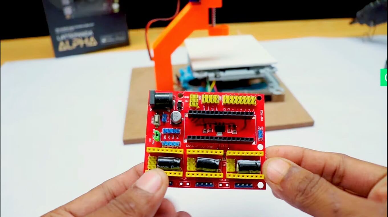
CNC Shield v4
CNC Shield V4.0 has 3 slots on the PCB board for stepper motor drive modules and one slot for Arduino Nano. It can drive 3 stepper motors by Arduino Nano. CNC Shield V4.0 has some GPIO pins available for connecting to two limit switches, as well as, CONFIG, I2C interface or serial communication.
For best mechanical strength, the PCB has been routed to coincide with two mounting screw positions. Power for 3 stepper motor drive modules and Nano board is supplied via an external power jack (DC 12V). **Caution**: Always remove the Arduino Nano board before switching CNC Shield V4.0 power on or off.
This CNC machine is designed to be used with the Arduino nano microcontroller board. The shield comes with all the necessary hardware and software to get started with CNC milling. With the Arduino CNC Shield v4, users can create parts and prototypes with greater accuracy and precision than ever before. The machine is perfect for hobbyists, makers
FIX THE HARDWARE:
I have used the techniques below:
https://www.instructables.com/id/Fix-Cloned-Arduino-nano
Electronic Connections – 3D Printed Mini CNC Machine
The connections are simple. You need to use one driver for each motor. The next thing is to connect the stepper motors with the CNC shield. You have to connect the x-axis stepper motor with the x-axis of the CNC shield and the y-axis stepper motor with the y-axis of the CNC shield.
After attaching the stepper motors, you have to attach the servo motor to the CNC shield. Follow the steps to connect the servo in the CNC shield
(1) Positive pin of servo motor – +5 volt pin of CNC shield
(2) Negative pin of servo motor – Gnd pin of CNC shield
(3) Signal pin of servo motor – +Z pin of CNC shield
Now our circuit is prepared to work. Give a 5-volt power supply to the CNC shield and Arduino nano shield. If the voltage given to the CNC shield is more than 5 volts, then there is a chance of damage to stepper motors. So it is always preferred to use a 5-volt dc supply
Benbox Softwer Configuration
How to set up Benbox?
It is time to set up the Benbox software.
- Download the Benbox software from this website https://benbox.updatestar.com/
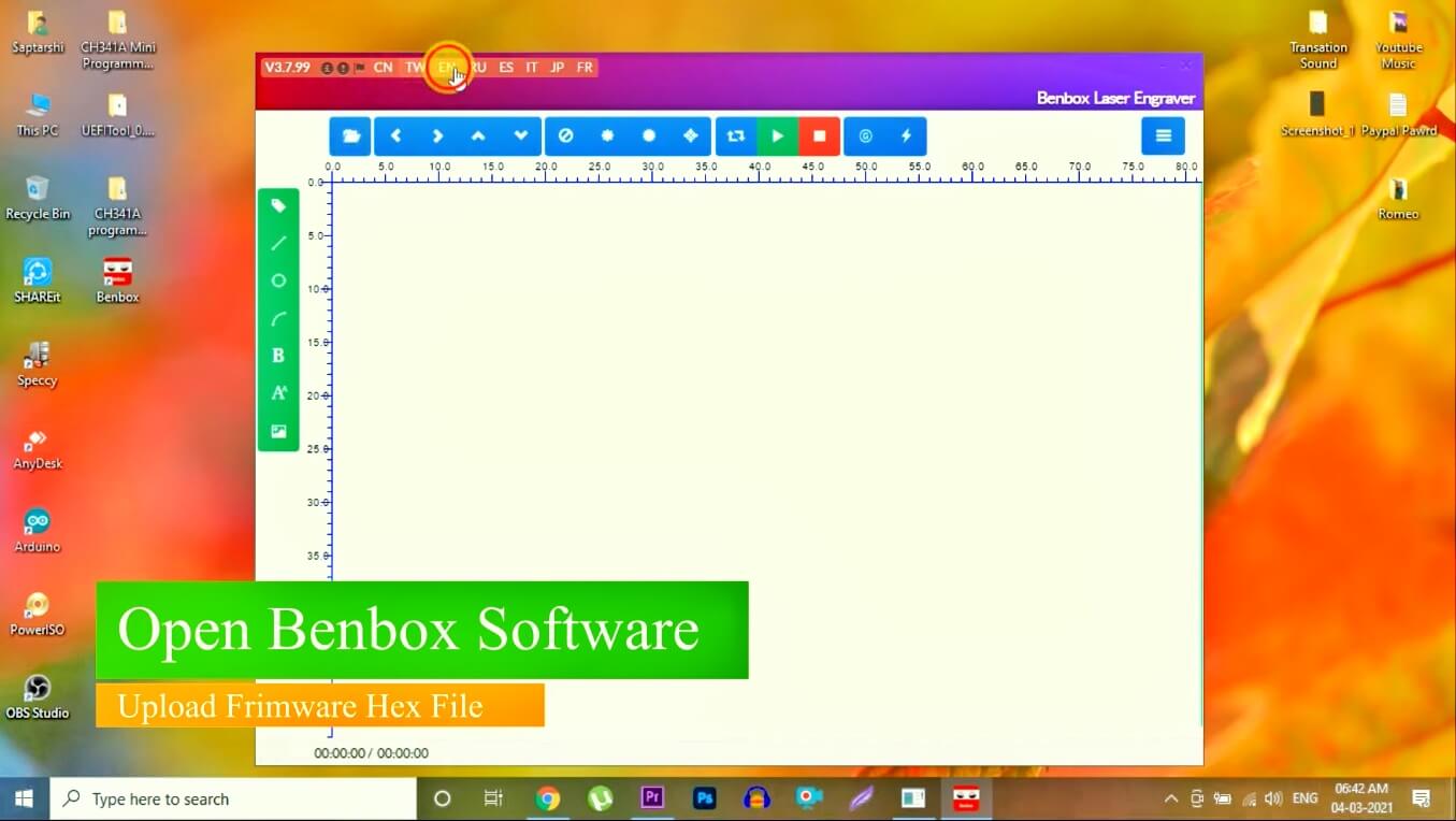
- Install it on your computer. After this open the software and select the language you prefer.
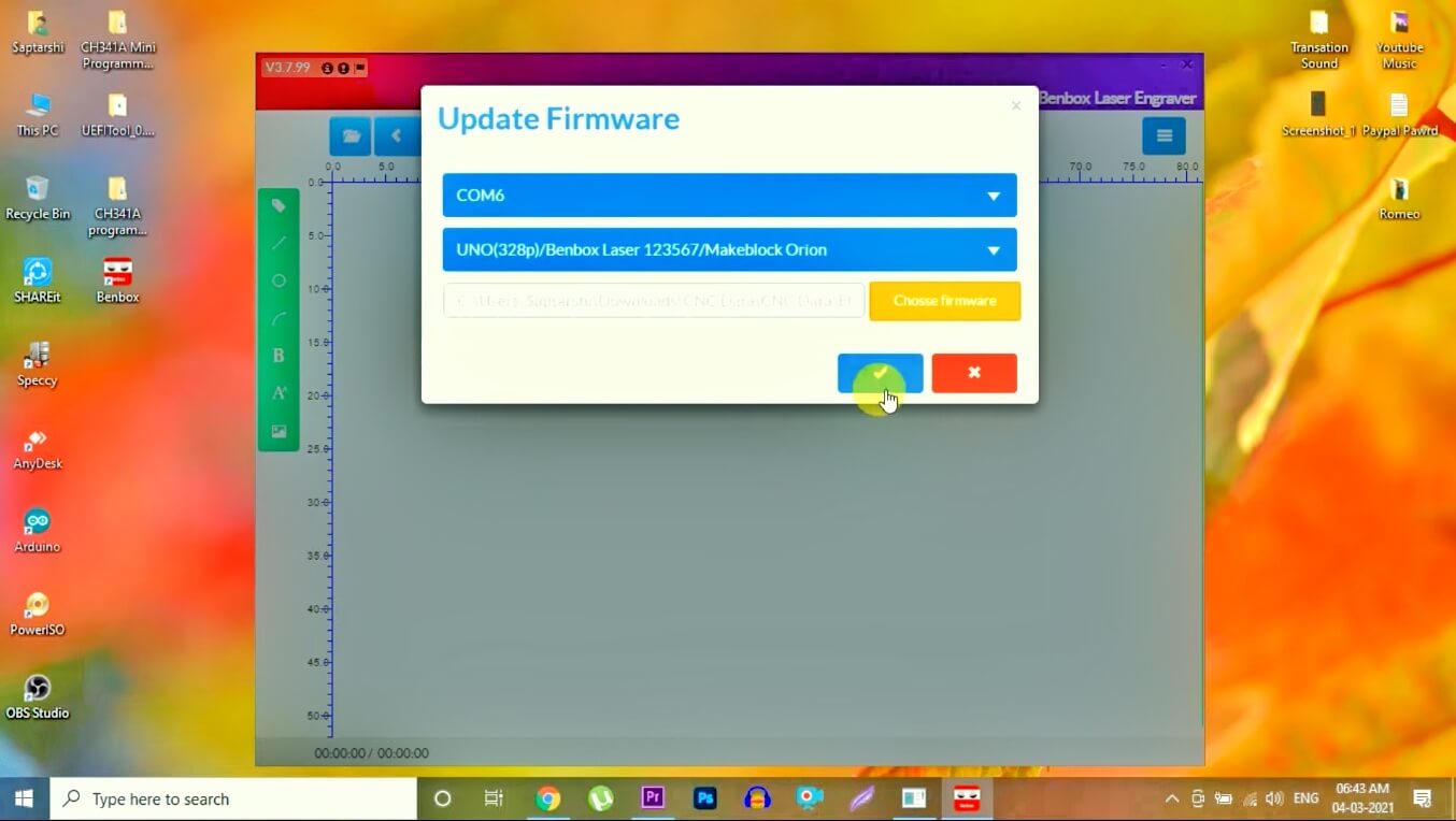
- Then you have to choose the port and Arduino type. Also, you have to upload the firmware in the Benbox software.
- Now you have to change some settings in the Benbox software as per the requirement.
- Click on the three bars at the top right corner of the Bandbox software and then follow the steps.
Bandbox software settings
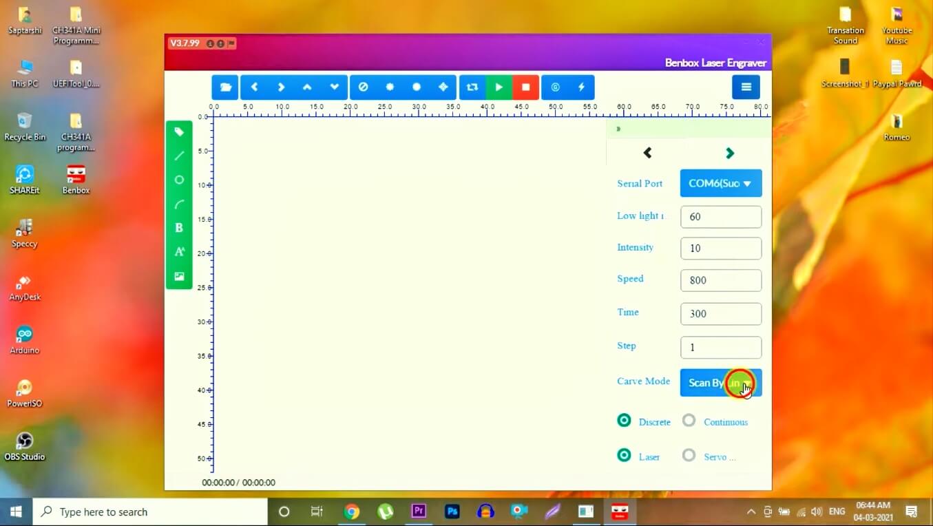
- Select the serial port of your Arduino.
- Then define the “pen up” and “pen down” values. These values will define the angle of the servo motor. By default, the “pen up” value is assigned to the servo. When the CNC plotter starts to draw something, the “pen down” value is assigned to the servo. As a result, the servo will create an angle for which the pen will be down to draw something.
- Also, set up the “speed” and “time” as per the requirement.
- Define the “step” value according to the size of the drawing surface. This value will define the steps of the stepper motor. By increasing or decreasing the value of “step”, you can increase or decrease the size of the image.
- Select the curve mode as “outline”. Then select the “servo”. After this, you have to define the pin layout for the x-axis and y-axis stepper motor and the servo motor in the Benbox software.
- Define the step pin of x-axis “2” and y-axis “3”.
- Define the dir pin of x-axis “5” and y-axis “6”.
- Select the servo pin “11” and “0”.
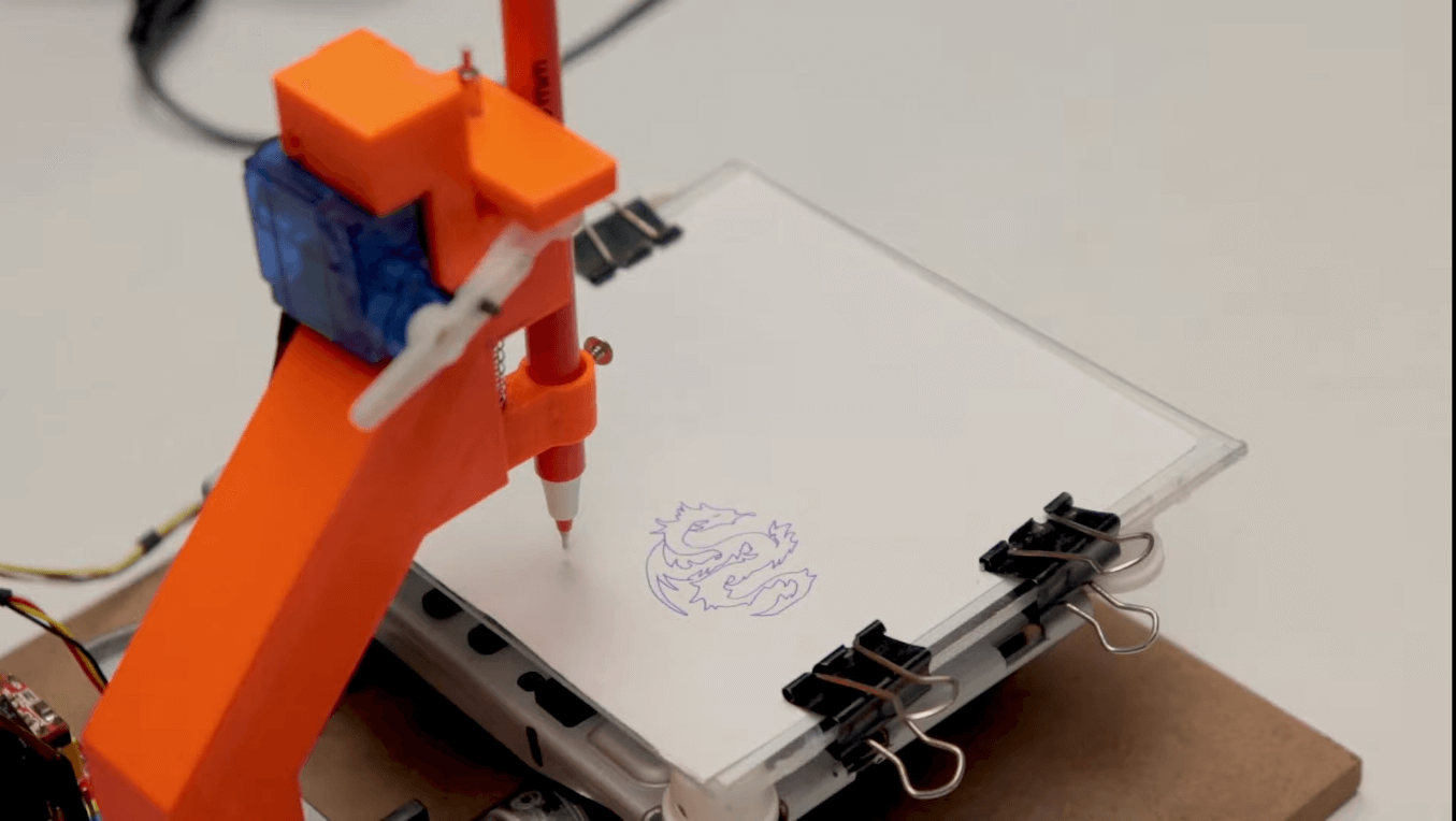
Now choose a picture from your computer and upload it in the Benbox software. Then click on the run button. The CNC plotter will start drawing the same picture that is uploaded in the Benbox software.
Open the Benbox software and upload firmware Hexfile then note the value as show a picture
- plug the CNC in
- go into the blue menu in the software and press connect
- find an image you want to line, open it
- Press play
Finish
Thanks for watching, I hope you liked it, if yes please subscribe to my Youtube channel
And if there is some problem in making a project, then you can message us, we will be happy to help you
Thank you for your reading!!!



7 Comments
Hello, very nice project.
Where we can found the stl for the pen holder.
Best regards
thanks Sir
please check again
My first day of u r web site
I am glad that you came to our website. How can we help you😊
Hello sir
Can I used Benbox software in L293D Motor Driver Shield and arduino uno?
No bro
Pingback: Control 28BYJ-48 Stepper Motor With Raspberry Pi Pico