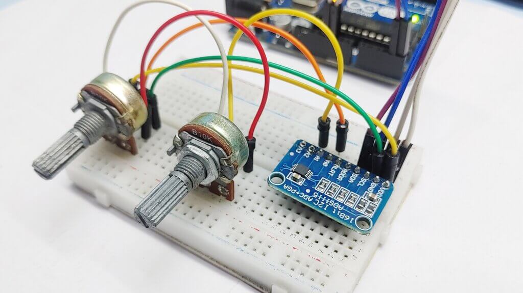
In this article, we will be discussing how to interface ADS1115 16-bit ADC with an Arduino. ADS1115 is a 4-channel, 16-bit analog-to-digital converter (ADC). We will use this ADS1115 ADC converter to read analog voltages from a 10K potentiometer and display it on Serial Monitor and 16×2 LCD I2C Display.
ADS1115 board is a low-power, high-precision, 16-bit analog-to-digital converter (ADC) that you can use with Arduino, ESP8266/32, Raspberry Pi, or any other Microcontrollers
Required Material
We need the following components to learn about the ADC Module in detail.
- Arduino Nano
- ADS1115 ADC Module
- 16×2 I2C LCD Display
- 10K Potentiometer
- Breadboard
- Jumper Wires
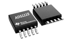
ADS1115 Chip
ADS1115 chip is a 16-bit analog-to-digital converter (ADC) from Texas Instruments. It is invented to provide high-precision and low-noise analog-to-digital conversion for analog sensors.
- Supply Voltage: 2.0-5.5 VDC
- 16-bit Resolution
- Continuous current consumption: 150uA
- 4 channels in individual mode, 2 channels in comparator mode
- Communication interface: I2C
- The internal stabilized reference voltage (Vref)
- Programmable Comparator
- Programmable Data Rate: 8sps To 860sps
- Internal Oscillator
- Internal PGA (Programmable Gain Amplifier).
- Pin-selectable Addresses
- Four Single-ended Or Two Differential Inputs
- Programmable Comparator
- Operating Temperature Range:
–40°C to +125°C - Single-Cycle Settling
ADS1115 Chip Pin Configuration

ADS1115 chip has a total of 10 pins. The pin configuration of the ADS1115 chip is as follows:
| 1 | Digital input(ADDR) | I2C slave address select |
| 2 | Digital output(ALERT/RDY) | Comparator output |
| 3 | Analog(GND) | Ground |
| 4 to 7 | Analog input(AIN0 to AIN3) | Analog input 0-3 |
| 8 | Analog(VDD) | Power supply. |
| 9 | Digital I/O(SDA) | Serial data. Transmits and receives data |
| 10 | Digital input(SCL) | Serial clock input. locks data on SDA |
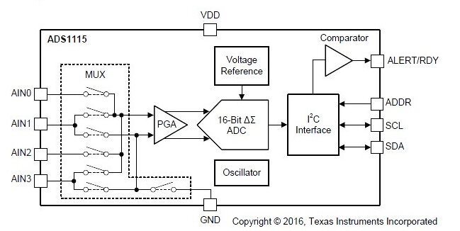
ADS1115 Block diagram
The functional block diagram consists of several main components:
A multiplexer (MUX) controls the selected input signal (AIN0 to AIN3). Next, the selected signal routes to the Programmable Gain amplifier (PGA). Programmed to amplify (PGA) that can amplify the input signal by a factor of 2, 4, 8, or 16 to enhance the resolution and accuracy of the conversion.
After that, the input is converted by a 16-bit Delta Sigma converter that converts the analog input signal into a 16-bit digital value.
The reference voltage generator is a key module in the ADC. It provides a relatively stable and accurate voltage reference for the ADC. The oscillator provides the internal clock signals for the ADC and the I2C communication interface. the converter uses a voltage reference and oscillator to measure the input signal.
Finally, the result of the conversion goes into the I2C interface. The comparator also provides a signal to the external interface that the result is ready for fetching.
See the more information ADS1115 Datasheet
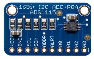
ADS1115 Module
ADS1115 module is an Analog-to-Digital Converter (ADC) with a 16-bit ADC resolution with four input channels. it is developed for use with analog sensors, such as temperature sensors, load cells, and force sensors.
ADS1115 module is commonly used to convert analog signals into digital signals. it is used for various Arduino, Raspberry Pi, ESP32, and other similar microcontrollers that support I2C communication.
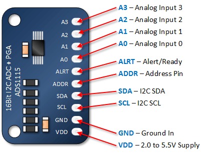
The ADS1115 Module has a total number of 10 Pins.
ADS1115 Pinout
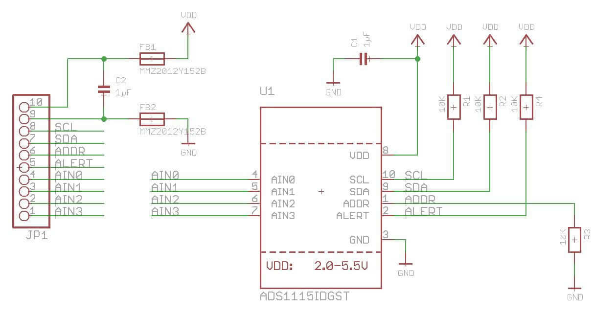
ADS1115 Module Schematic
Here’s a basic schematic for the ADS1115 module:
This schematic provides a basic setup for using the ADS1115 module with microcontrollers.
ADS1115 Applications
- Portable instrumentation
- Consumer goods
- Battery monitoring
- Temperature measurement
- Factory automation and process controls
ADS115 Input Mode
The 4 inputs can be configured to operate in 3 different modes.
- Single-Ended Mode
- Comparator Mode
- Differential Mode
ADS1115 I2C Address Selection
You can select from one of four available addresses by connecting the ADDR pin as detailed below. The board already has a pull-down resistor connecting ADDR to GND for a default address of 0x48.
| I2C Address | Connect to ADDR |
|---|---|
| 0x48 | No connection necessary |
| 0x49 | VDD |
| 0x4A | SDA |
| 0x4B | SCL |
The input voltage to be measured must always be less than the supply voltage of ADS1115 + 0.3 volts, otherwise, this digital analog converter will be destroyed!
For Example :
- If you are supplied with + 5V, the voltage to be measured must not exceed 5.3 volts
- If you are supplied with + 3.3V, the voltage to be measured must not exceed 3.6 volts
Interfacing ADS1115 Module with Arduino
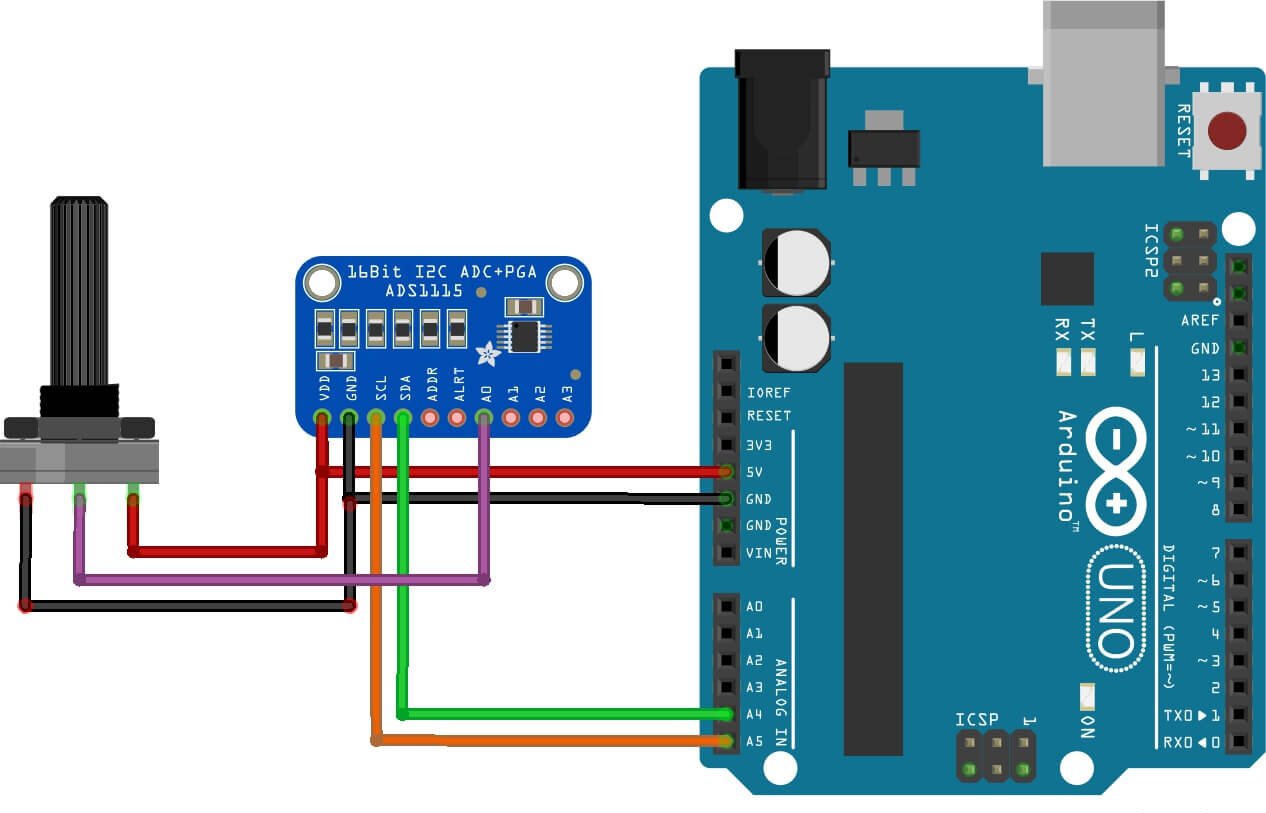
To interface an ADS1115 module with an Arduino, you can follow these steps:
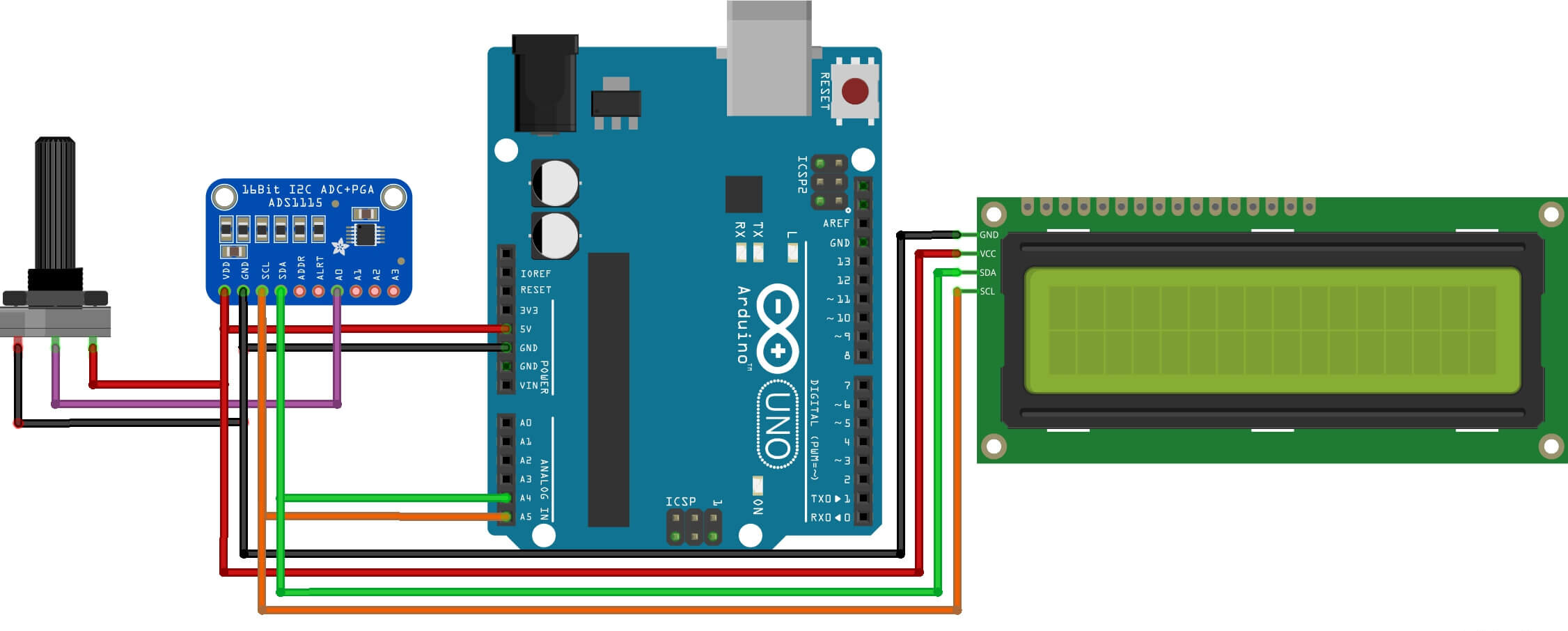
Connect the ADS1115 module to the Arduino using I2C Communications. Connect the ADS1115 SDA pin to the SDA pin on the Arduino A4, and connect the SCL pin to Arduino Pin A5. GND and VCC pins on the ADS1115 to the GND and 5V pins on the Arduino, respectively.
Code & Libriries
To install the ADS1115 Arduino library, you can follow these simple
- Open the Arduino IDE.
- Select “Sketch” from the menu bar, and then choose “Include Library” and “Manage Libraries“.
- In the “Library Manager“, type “ADS1X15” in the search bar and press enter.
- Look for the “Adafruit ADS1X15” library and select it.
- Then click the “Install” button to install the library.
Adafruit develops the library and it is available for download from the Arduino Library Manager or the Adafruit GitHub repository.
ADS1115 Arduino library is a simple library for interfacing ADS1115 module and can simplify the process of reading analog input voltages with an Arduino.
This code includes the required Wire library for I2C communication and the Adafruit ADS1X15 library for the ADS1115 ADC.
Source Code serial print
|
1 2 3 4 5 6 7 8 9 10 11 12 13 14 15 16 17 18 19 20 21 22 23 24 25 26 27 28 29 30 31 32 33 34 35 |
#include "ADS1X15.h" ADS1115 ADS(0x48); void setup() { Serial.begin(115200); Serial.println("Hello!"); Serial.println(__FILE__); Serial.print("ADS1X15_LIB_VERSION: "); Serial.println(ADS1X15_LIB_VERSION); ADS.begin(); } void loop() { ADS.setGain(0); int16_t val_0 = ADS.readADC(0); int16_t val_1 = ADS.readADC(1); int16_t val_2 = ADS.readADC(2); int16_t val_3 = ADS.readADC(3); float f = ADS.toVoltage(1); // voltage factor Serial.print("\tADC0: "); Serial.print(val_0); Serial.print('\t'); Serial.println(val_0 * f, 3); Serial.print("\tADC1: "); Serial.print(val_1); Serial.print('\t'); Serial.println(val_1 * f, 3); Serial.print("\tADC2: "); Serial.print(val_2); Serial.print('\t'); Serial.println(val_2 * f, 3); Serial.print("\tADC3: "); Serial.print(val_3); Serial.print('\t'); Serial.println(val_3 * f, 3); Serial.println(); delay(1000); } |
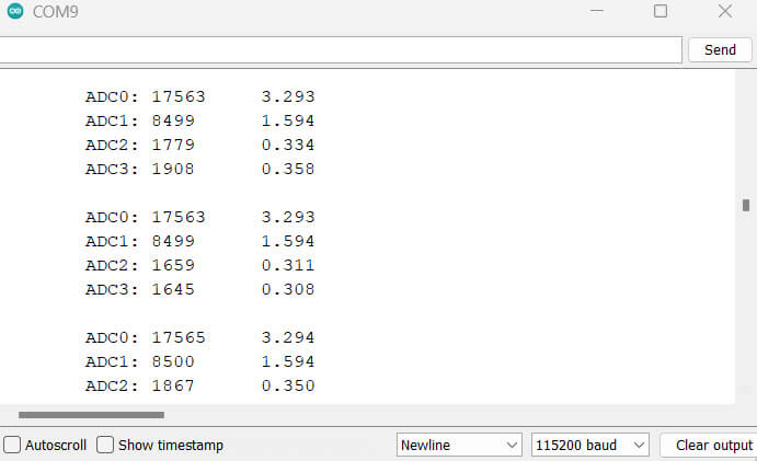
Using the basic example code from the ADS1115 example folder, we can test the sensor. Copy the following code and upload it to the Arduino UNO Board.
Upload the code, then open the Serial Monitor. The Serial Monitor will show the ADC value for all 4 outputs along with the output voltage.
Read ADS1115 ADC On 16×2 I2C Display with Arduino
Source Code
Here is an example code to read values from the ADS1115 ADC and display them on a 16×2 I2C display with an Arduino:
|
1 2 3 4 5 6 7 8 9 10 11 12 13 14 15 16 17 18 19 20 21 22 23 24 25 26 27 28 29 30 31 32 33 34 35 36 37 38 39 40 41 42 43 44 45 46 47 |
#include "ADS1X15.h" #include <LiquidCrystal_I2C.h> LiquidCrystal_I2C lcd(0x27, 16, 2); ADS1115 ADS(0x48); void setup() { Serial.begin(115200); Serial.println(__FILE__); Serial.print("ADS1X15_LIB_VERSION: "); Serial.println(ADS1X15_LIB_VERSION); lcd.init(); lcd.backlight(); ADS.begin(); } void loop() { ADS.setGain(0); int16_t val_0 = ADS.readADC(0); int16_t val_1 = ADS.readADC(1); int16_t val_2 = ADS.readADC(2); int16_t val_3 = ADS.readADC(3); float f = ADS.toVoltage(1); // voltage factor Serial.print("\tADC0: "); Serial.print(val_0); Serial.print('\t'); Serial.println(val_0 * f, 3); Serial.print("\tADC1: "); Serial.print(val_1); Serial.print('\t'); Serial.println(val_1 * f, 3); Serial.print("\tADC2: "); Serial.print(val_2); Serial.print('\t'); Serial.println(val_2 * f, 3); Serial.print("\tADC3: "); Serial.print(val_3); Serial.print('\t'); Serial.println(val_3 * f, 3); Serial.println(); lcd.clear(); lcd.setCursor(0, 0); lcd.print("ADC Val:"); lcd.print(val_0); lcd.setCursor(0, 1); lcd.print("Voltage:"); lcd.print(val_0 * f, 3); lcd.print("V"); delay(1000); } |
Results
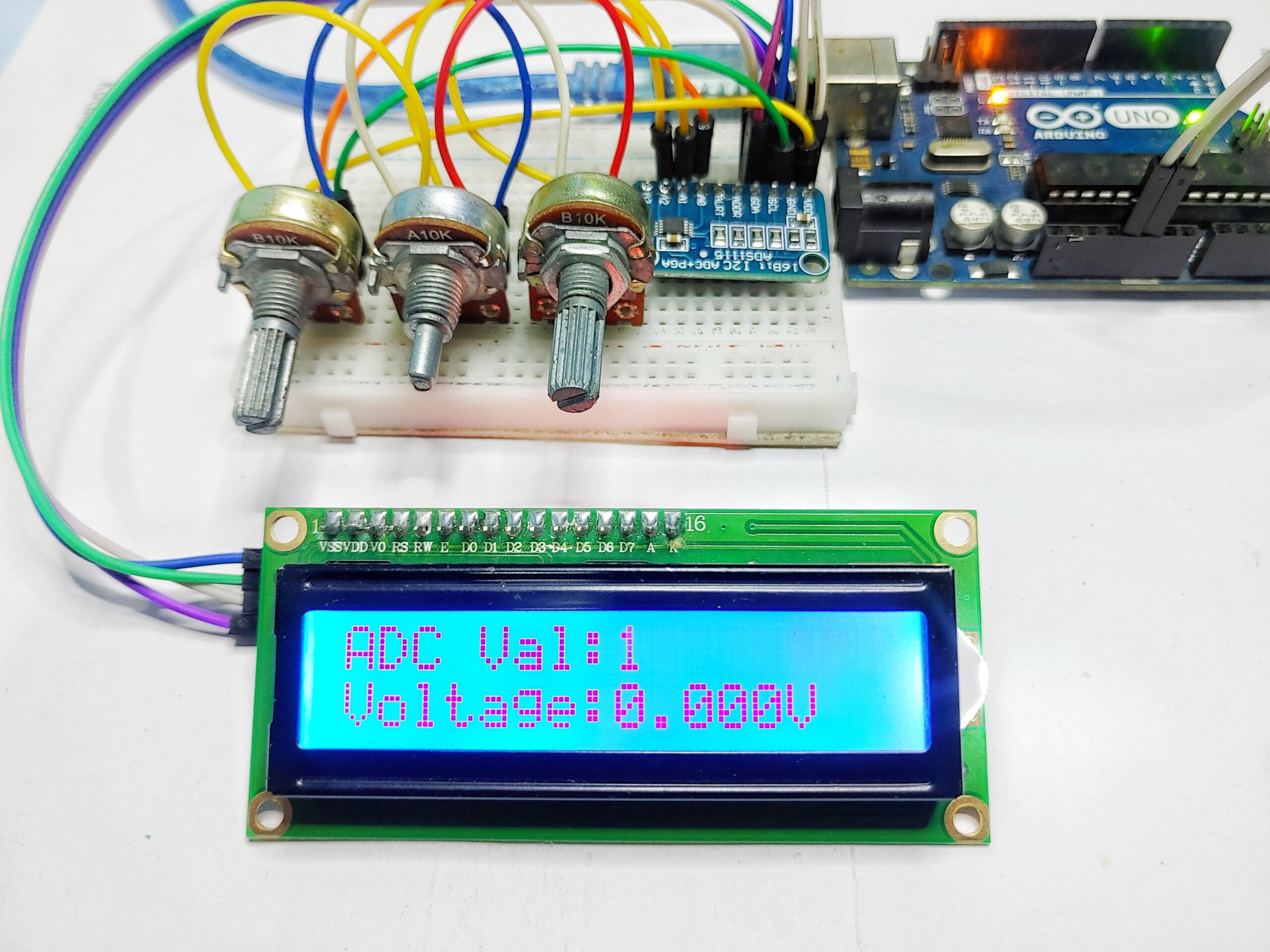
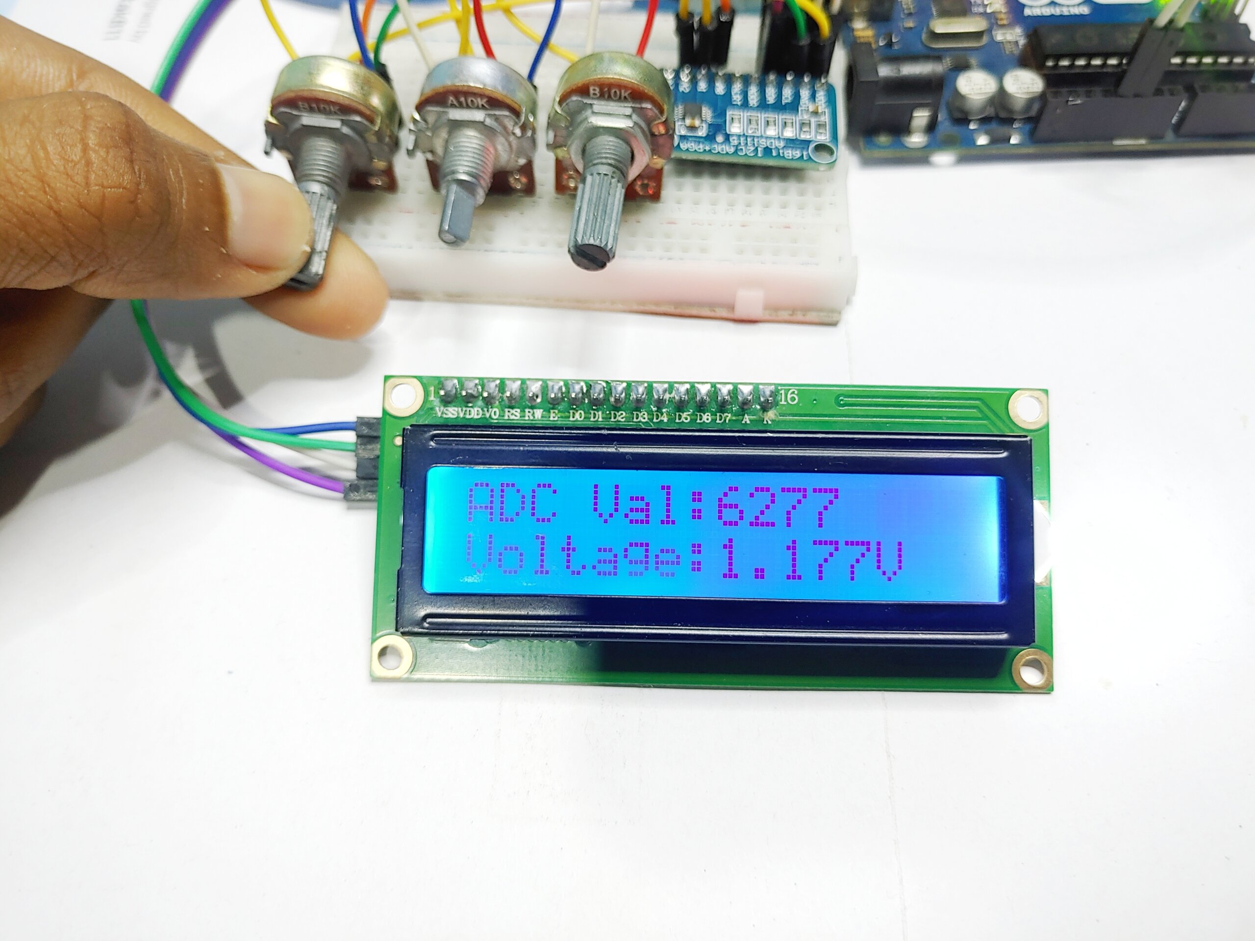
The module is ready for testing after uploading the above code in Arduino UNO. For this test, we will need a multimeter. The LCD will display the ADC Value and measured Voltage.

