Introduction
This tutorial shows you how to use ADS1115 Analog-to-Digital Converter with Raspberry Pi Pico. The ADS1115 is a 4-channel, 16-bit analog-to-digital converter (ADC), that we can use with Raspberry Pi, ESP8266/ESP32, or other Microcontrollers. check out Raspberry Pi Pico Projects for Beginners [2022]
Required Material
- Raspberry Pi Pico
- ADS1115 Module
- Jumper Wires
- Breadboard
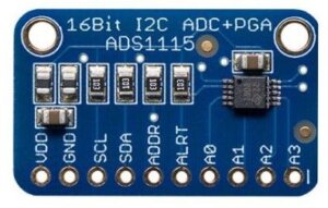
ADS115 Analog-to-digital converters
Analog-to-digital converters (ADC) are used to convert analog signals into digital signals manufactured by Texas Instruments. The ADS1115 is a low-cost, 4-channel, I2C-compatible module. In this tutorial, we will interface the ADS1115 with a Raspberry Pi Pico and use it to measure the voltage. It has a ±2.048V full-scale range and can convert signals at up to 860 samples per second.
ADS1115 has four input channels that can be separately configured for differential or single-ended measurements. This allows you to count multiple analog signals at the exact time with accurate measurements of instruments and signals.
To learn more about the ADS1115 module, you can check our previous posts provide detailed information about the ADS1115, its features, and how to interface it with different microcontrollers like Arduino, ESP8266/ESP32, and Raspberry Pi.
-
How to Interface ADS1115 16-Bit ADC with Arduino
-
How To Use ADS1115 16-Bit ADC with ESP32
-
How to Interface ADS1115 16-Bit ADC with ESP8266
ADS1115 Features
- ADC Bit rate – 16-bit Resolution
- Input voltage 2.0-5.5v
- 4 Channel ANO AN1 AN2 AN3 or 2 differential inputs
- Interface type I2C Protocol
- Programmable Comparator
- Programmable data rate – 8sps-860sps
- Wide Supply Range
- Low Current Consumption
- Continuous-Conversion Mode
- Single-shot mode – Auto shut-down
- Programmable Data Rate
- Programmable Comparator
- Single-Cycle Settling
- Internal Low-Drift Voltage Reference
- Internal Oscillator
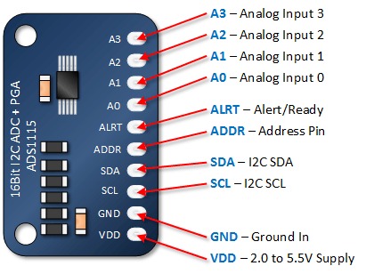
ADS115 Pinout
- VDD = 3.3V or 5V
- GND = Ground
- SCL = I2C SCL
- SDA = I2C SDA
- ADDR = I2C Address. defaut I2C Address is 0x48.
- ALRT= Alert / Ready.
- A0 = Analog input 0
- A1 = Analog input 1
- A2 = Analog input 2
- A3 = Analog input 3
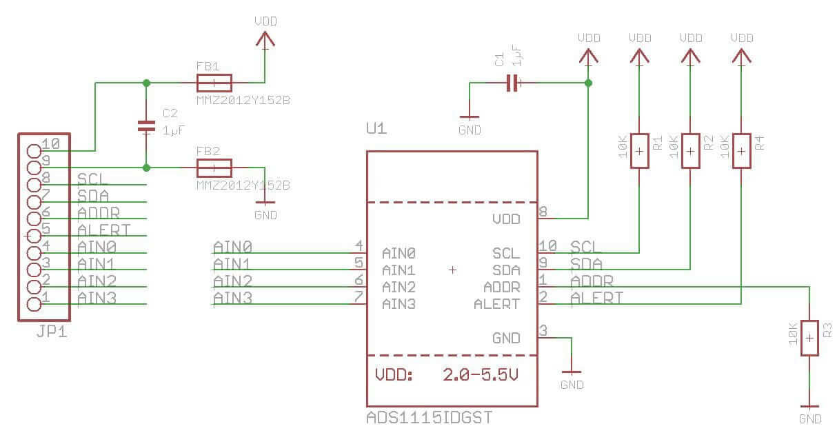
ADS1115 Schematics
Interfacing ADS1115 Analog-to-Digital Converter with Raspberry Pi Pico
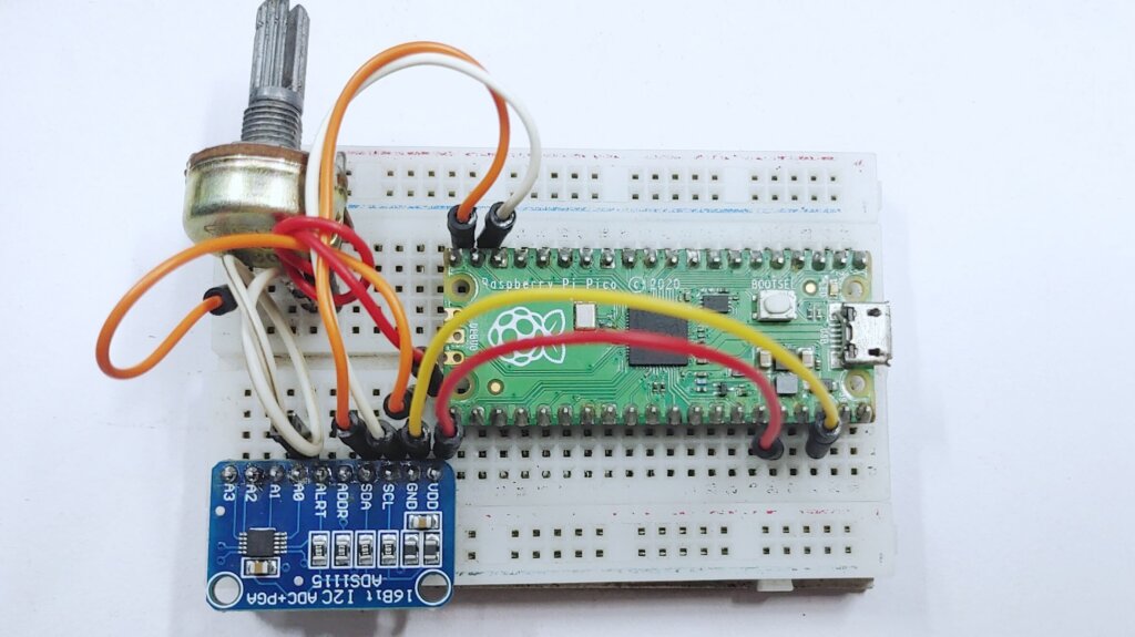
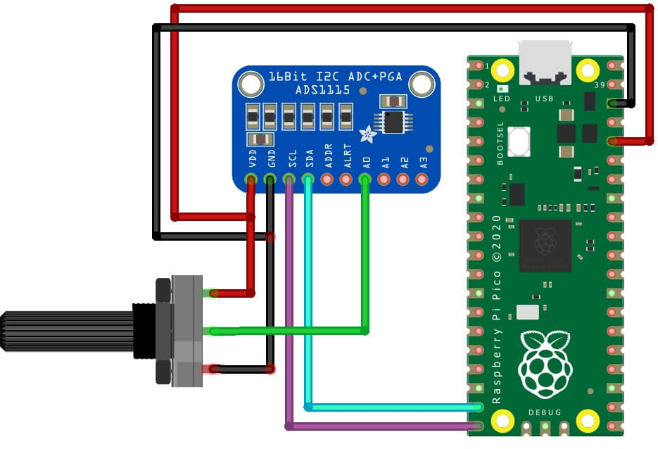
The wiring connection for interfacing the ADS1115 ADC module with Raspberry Pi Pico is fairly simple. Here’s the wiring diagram:
You can also follow my mapping.
| ADS1115 module | Raspberry Pi pico |
|---|---|
| VDD | 3.3V |
| GND | GND |
| SCL | GP15 |
| SDA | GP14 |
Connect a potentiometer to the ADS1115. Connect the GND & VCC to the GND, the 3V pin to the Pico board, and the potentiometer middle pin to any one of the four channels of the ADS1115 in my case I use it in A0.
| Potentiometer | ADS1115 module |
|---|---|
| VCC | 3.3V |
| SIGNAL | A0 |
| GND | GND |
Connect ADS1115 With Raspberry Pi Pico
Micopython Code – ADS1115 & Raspberry Pi Pico
Copy the given Micropython code and save it in the Raspberry Pi Pico directory as main.py
|
1 2 3 4 5 6 7 8 9 10 11 12 13 14 15 16 17 18 19 20 21 22 23 24 25 26 27 28 29 30 31 32 33 34 35 36 37 38 39 40 41 |
import utime from machine import I2C, Pin class ADCDevice: def __init__(self, i2c_bus, address=72): self.i2c = i2c_bus self.address = address def read_config(self): self.i2c.writeto(self.address, bytearray([1])) result = self.i2c.readfrom(self.address, 2) return result[0] << 8 | result[1] def read_value(self): self.i2c.writeto(self.address, bytearray([0])) result = self.i2c.readfrom(self.address, 2) config = self.read_config() config &= ~(7 << 12) & ~(7 << 9) config |= (4 << 12) | (1 << 9) | (1 << 15) config = [int(config >> i & 0xff) for i in (8, 0)] self.i2c.writeto(self.address, bytearray([1] + config)) return result[0] << 8 | result[1] @staticmethod def val_to_voltage(val, max_val=26100, voltage_ref=3.3): return val / max_val * voltage_ref i2c_bus = I2C(1, freq=400000, scl=Pin(15), sda=Pin(14)) devices = i2c_bus.scan() for device in devices: print(device) adc = ADCDevice(i2c_bus) print(bin(adc.read_config())) while True: val = adc.read_value() voltage = adc.val_to_voltage(val) print("ADC Value:", val, "Voltage: {:.3f} V".format(voltage)) utime.sleep(0.5) |
This code reads the ADC value and the voltage reading from the potentiometer and outputs them to the Thonny shell. you can run this script on your Raspberry Pi Pico to read the potentiometer values by using the ADS1115 module.
Conclusion
The code has been uploaded and is now ready for testing.
You will get a measured voltage value on the shell console. The read voltage is a maximum of 3.3V. and min voltage is 0V.
Testing
A multimeter will be needed for this purpose to measure voltage.
You should be able to see the voltage values changing as you turn the potentiometer.
Raspberry Pi Pico Projects
- MFRC522 RFID Module With Raspberry Pi Pico Using MicroPython
- Interfacing Raspberry Pi Pico With VGA Monitor
- Water-Flowing LED Lights With Raspberry Pi Pico W
- Interfacing PIR Motion Sensor with Raspberry Pi Pico
- BME280 With Raspberry Pi Pico W Using MicroPython

