Introduction
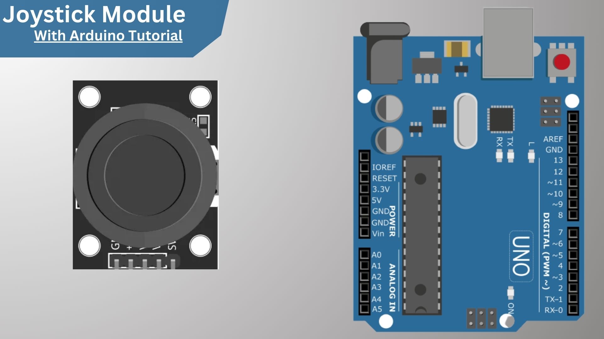
In this tutorial, we’ll be using a Joystick With Arduino. Joysticks are great for a whole host of applications, including gaming, robotics, and more. With an Arduino, you can easily interface with a joystick and use it to control anything you want. Let’s get started! Analog joysticks are used in many devices, such as video game controllers, drawing tablets, and industrial control panels. They are also used in some robots and other mechanical control systems.
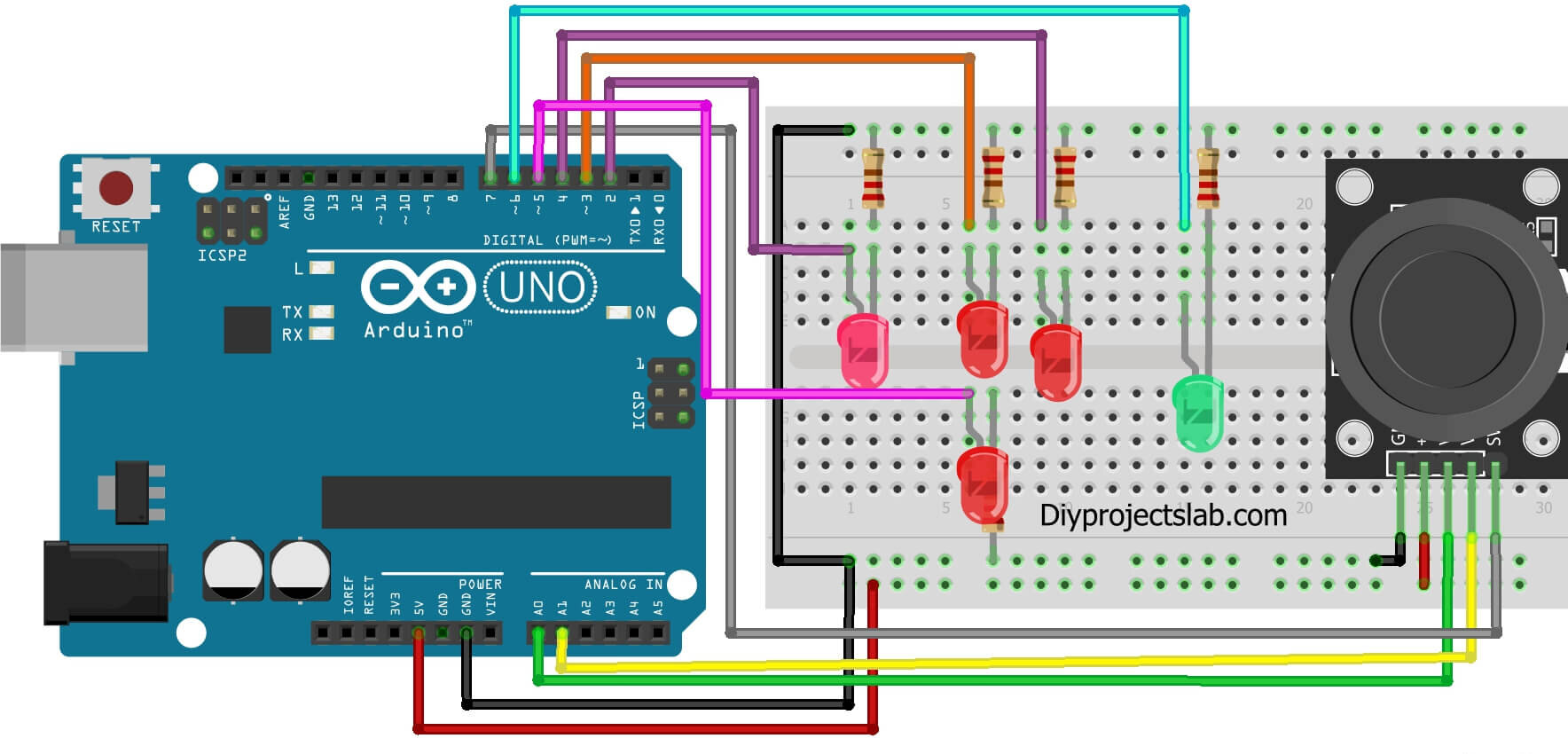
We’ll use the Arduino to read the position of the joystick and the button and use that information to control the color of an LED.
List of material
What is an Analog Joystick?
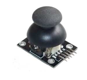
A JoyStick is an input device that allows a user to control a character or object on a screen. They are typically used in video games and are made up of a few key components: a stick, buttons, and an actuator. The stick is the main component and is used to control the character or object.
The buttons are used to perform different actions, such as jumping or shooting. The actuator is a device that converts the user’s input into an electrical signal. JoySticks typically use potentiometers to measure the position of the stick. A potentiometer is a variable resistor that changes its resistance based on the position of the wiper.
Joystick module specifications and features:
- Model: KY-023
- Operating voltage: 3.3V – 5VDC
- Analog axes: X and Y
- Button: Z axis
Joystick module pinout
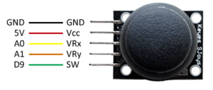
Let’s have a look at the pinout of the 2-axis Thumb Joystick module.
- GND is the Ground Pin to which we connect the GND pin on the Arduino.
- VCC supplies power for the module. You can connect it to 5V output from your Arduino.
- VRx gives a readout of the joystick in the horizontal direction (X-coordinate)
- VRy gives a readout of the joystick in the vertical direction (Y-coordinate)
- SW is the output from the push button. It’s normally open, meaning the digital readout from the SW pin will be HIGH. When the button is pushed, it will connect to GND, giving output LOW.
How to connect an Analog Joystick to an Arduino?
Code for reading data from the joystick
|
1 2 3 4 5 6 7 8 9 10 11 12 13 14 15 16 17 |
#define joyX A0 #define joyY A1 void setup() { Serial.begin(9600); } void loop() { // put your main code here, to run repeatedly: xValue = analogRead(joyX); yValue = analogRead(joyY); //print the values with to plot or view Serial.print(xValue); Serial.print("\t"); Serial.println(yValue); } |
Control LED Using Joystick moduleJoystick With Arduino
Code for Control LED with Joystick module
|
1 2 3 4 5 6 7 8 9 10 11 12 13 14 15 16 17 18 19 20 21 22 23 24 25 26 27 28 29 30 31 32 33 34 35 36 37 38 39 40 41 42 43 44 45 46 47 48 49 50 51 52 53 54 55 56 57 58 59 60 61 62 63 64 65 66 67 68 69 70 71 72 73 74 75 76 77 78 |
//Author : https://www.diyprojectslab.com/ int xvalue = 0; //Store the value read from the potentiometer - X Axis int value = 0; //Store the value read from the potentiometer - Y Axis int value z = 0; //Store the value read from the button - Z Axis int leftpin = 2; //Left LED Pin int pinledupper = 3; // Upper LED Pin int right-pin = 4; //Right LED pin int bottompin = 5; //Lower LED pin int pinoledz = 6; //Led pin Z Axis void setup () { pinMode ( 7, INPUT ) ; //Z axis pin Serial. begin ( 9600 ) ; pinMode ( leftpin, OUTPUT ) ; pinMode ( pinledupper, OUTPUT ) ; pinMode ( rightledpin, OUTPUT ) ; pinMode ( bottompin, OUTPUT ) ; pinMode ( pinledz, OUTPUT ) ; } void loop () { //The lines below turn off all the LEDs digitalWrite ( pinLeft, LOW ) ; digitalWrite ( pinledupper, LOW ) ; digitalWrite ( rightledpin, LOW ) ; digitalWrite ( lowerpin, LOW ) ; digitalWrite ( pinledz, LOW ) ; //Read the value of the potentiometer connected to the analog port A0 - Axis X xvalue = analogRead ( 0 ) ; //Show the X-axis value on the serial monitor Serial. print ( "X:" ) ; Serial. print ( xvalue, DEC ) ; //Test the X-Axis value and activate the corresponding LED if ( xvalue > -1 & xvalue < 200 ) { digitalWrite ( lowerpin, HIGH ) ; // Turn on the lower LED } if ( xvalue > 700 & xvalue < 1025 ) { digitalWrite ( pinledupper, HIGH ) ; // Turn on the upper LED } //Read the value of the potentiometer connected to the analog port A1 - Axis Y valory= analogRead ( 1 ) ; //Display the Y-axis value on the serial monitor Serial. print ( " | Y:" ) ; Serial. print ( value, DEC ) ; //Test the Y Axis value and activate the corresponding LED if ( valory > -1 & valory < 200 ) { digitalWrite ( rightledpin, HIGH ) ; // turn on the right led } if ( valory > 700 & valory < 1025 ) { digitalWrite ( pinLeft, HIGH ) ; // turn on the left led } //Read the value of Digital port 7 - Z Axis valuez = digitalRead ( 7 ) ; //Display the Z Axis value on the serial monitor Serial. print ( " | Z: " ) ; Serial. println ( valuez, DEC ) ; //If the Z Axis button is pressed, the green LED lights up if ( valuez != 1 ) { digitalWrite ( pinledz, HIGH ) ; } } |
Here are some more Posts for you:
- How to Use an LDR Sensor With Arduino Tutorial
- Explain MQ2, MQ3, MQ7 and MQ135 Gas Sensor With Arduino Tutorials
- Tutorial DS1307 RTC Module With Arduino
- Interface HC-SR04 Ultrasonic Sensor With Arduino
- Interface Rotary Encoder With Arduino, How It Works, Codes
- Interface SIM800L with Arduino Tutorial – How It Works, Codes

