In this tutorial, we will learn How o use an MPU-6050 accelerometer and gyroscope. We will be using a 0.96″ OLED display to display the data from the sensor. This project is excellent for beginners.
The MPU6050 module is an integrated MEMS (Micro-Electro-Mechanical System) that combines a 3-axis gyroscope and a 3-axis accelerometer which is used to measure acceleration, accurate velocity, orientation, and many other motion-related parameters of a system or object.
The MPU6050 is a popular accelerometer and gyroscope chip with high accuracy at an affordable price. check out the previous post How to use MPU6050 with Raspberry Pi Pico using MicroPython
Required Components
- Arduino board
- MPU6050 module
- 0.96″ OLED display
- Breadboard
- Jumper wires
MPU6050 Accelerometer and Gyroscope module
MPU6050 is a Micro-Electro-Mechanical System (MEMS) that features a three-axis MEMS gyroscope and a three-axis MEMS accelerometer. accelerometer measures linear acceleration in a gravitation field, which is the rate of change of velocity along a gravitational field, while the gyroscope measures rotational acceleration, which is the rate of change of angular velocity.
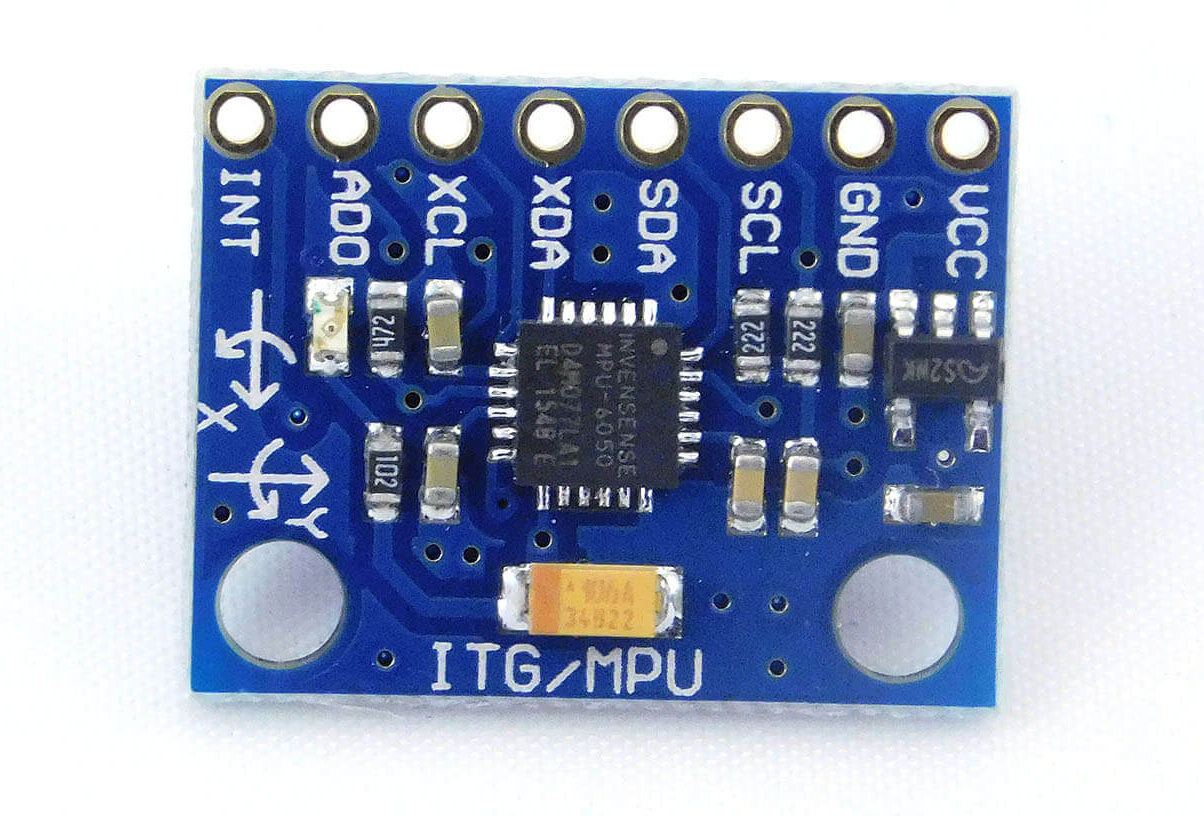
MPU6050 Pinout
MPU-6050 module has 8 pins.
- VCC: This pin is used to supply power from 3.3V to 5V
- GND: GND connected to the ground
- SCL: I2C clock pin
- SDA: I2C data pin
- XDA: Serial data
- XCL: Serial clock
- AD0: Set the address
- INT: Interrupt notifications Pin
Specification of MPU6050
Here are the specifications of the MPU-6050 Accelerometer and Gyroscope
- Power supply voltage: 3.3V – 5V
- Current consumption: 3.6mA and 50μA (sleep mode)
- Operating temperature range: -40°C to 85°C
- Accelerometer range: ±2g, ±4g, ±8g, or ±16g
- Gyroscope range: ±250°/s, ±500°/s, ±1000°/s, or ±2000°/s
- Resolution: 16-bit for both accelerometer and gyroscope
- Communication interface: I2C , Address: 0x68 (default) or 0x69 (alternate)
- Dimensions: 20mm x 16mm x 1.6mm
Other features
- Digital Motion Processor (DMP) for complex motion processing
- Motion detection with programmable interrupt
- Temperature sensor with ±1°C accuracy
MPU6050 Application
- Motion sensing
- Robotics
- Gaming
- Virtual reality
- Stabilization systems
- Drones and UAVs
- Navigation and orientation systems
- Health Monitoring and fall detection in elderly care
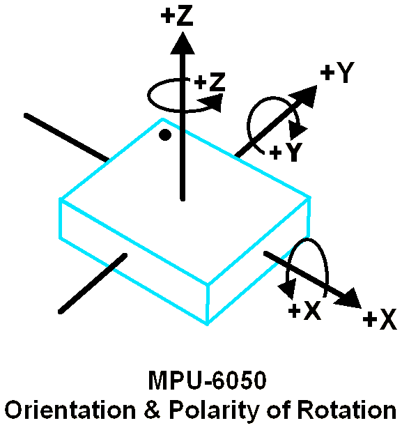
3-Axis Gyroscope
MPU6050 has a 3-axis gyroscope that uses Micro Electro Mechanical System (MEMS) technology to measure rotational velocity. The gyroscope consists of a tiny mass that moves back and forth in response to rotational motion. As the mass moves, it causes a change in capacitance, which is detected by the MEMS sensors.
These sensors convert the motion into an electrical signal, which is processed by the MPU6050 to determine the rotational velocity around each axis (X, Y, and Z).
3-Axis Accelerometer
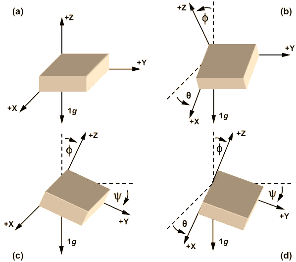
The MPU6050 has also a 3-axis accelerometer that measures how much the module is tilted in three different directions: left and right (X-axis), forward and backward (Y-axis), and up and down (Z-axis).
When MPU6050 is tilted, the mass inside the accelerometer moves, and this movement is detected by the MEMS sensors. then the sensor sends an electrical signal to MPU6050, which uses this data to calculate the angle of direction.
When you put MPU6050 on a flat surface, accelerometer values of 0 (zero) for acceleration along the X and Y axes, and a value of +1 for acceleration along the Z axis.
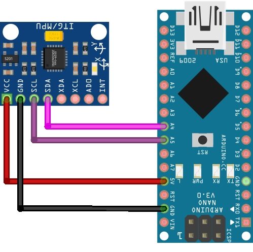
Wiring Between MPU6050 And Arduino
| MPU-6050 Pin | Arduino Pin |
|---|---|
| VCC | 5V |
| GND | GND |
| SDA | A4 |
| SCL | A5 |
Note: On some MPU6050 modules, the SDA and SCL pins may be marked as “SDA/SDI” and “SCL/SCK” respectively.
Example Code – MPU6050 Arduino
|
1 2 3 4 5 6 7 8 9 10 11 12 13 14 15 16 17 18 19 20 21 22 23 24 25 26 27 28 29 30 31 32 33 34 35 36 37 |
#include <Wire.h> const int MPU_addr=0x68; // I2C address of MPU6050 int16_t AcX,AcY,AcZ,Tmp,GyX,GyY,GyZ; void setup(){ Wire.begin(); Wire.beginTransmission(MPU_addr); Wire.write(0x6B); // PWR_MGMT_1 register Wire.write(0); // set to zero (wakes up the MPU6050) Wire.endTransmission(true); Serial.begin(9600); } void loop(){ Wire.beginTransmission(MPU_addr); Wire.write(0x3B); // starting with register 0x3B (ACCEL_XOUT_H) Wire.endTransmission(false); Wire.requestFrom(MPU_addr,14,true); // request a total of 14 registers AcX=Wire.read()<<8|Wire.read(); // 0x3B (ACCEL_XOUT_H) & 0x3C (ACCEL_XOUT_L) AcY=Wire.read()<<8|Wire.read(); // 0x3D (ACCEL_YOUT_H) & 0x3E (ACCEL_YOUT_L) AcZ=Wire.read()<<8|Wire.read(); // 0x3F (ACCEL_ZOUT_H) & 0x40 (ACCEL_ZOUT_L) Tmp=Wire.read()<<8|Wire.read(); // 0x41 (TEMP_OUT_H) & 0x42 (TEMP_OUT_L) GyX=Wire.read()<<8|Wire.read(); // 0x43 (GYRO_XOUT_H) & 0x44 (GYRO_XOUT_L) GyY=Wire.read()<<8|Wire.read(); // 0x45 (GYRO_YOUT_H) & 0x46 (GYRO_YOUT_L) GyZ=Wire.read()<<8|Wire.read(); // 0x47 (GYRO_ZOUT_H) & 0x48 (GYRO_ZOUT_L) Serial.print("AcX = "); Serial.print(AcX); Serial.print(" | AcY = "); Serial.print(AcY); Serial.print(" | AcZ = "); Serial.print(AcZ); Serial.print(" | Tmp = "); Serial.print(Tmp/340.00+36.53); // temperature formula Serial.print(" | GyX = "); Serial.print(GyX); Serial.print(" | GyY = "); Serial.print(GyY); Serial.print(" | GyZ = "); Serial.println(GyZ); delay(1000); } |
Results
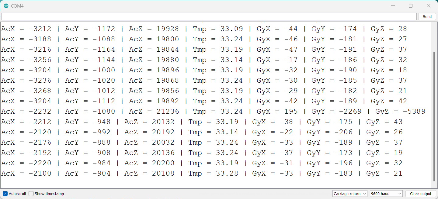
After uploading the code, you can open the Serial Monitor in the Arduino IDE to check the output values. The MPU6050 gyro/accelerometer sensor can detect the angular position of the X, Y, and Z axes by tilting \sensor. The output values for each axis can be displayed on the serial monitor.
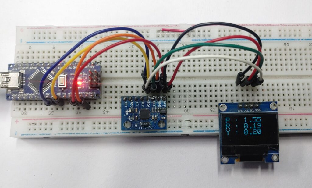
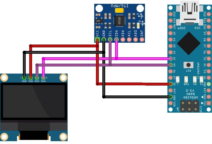
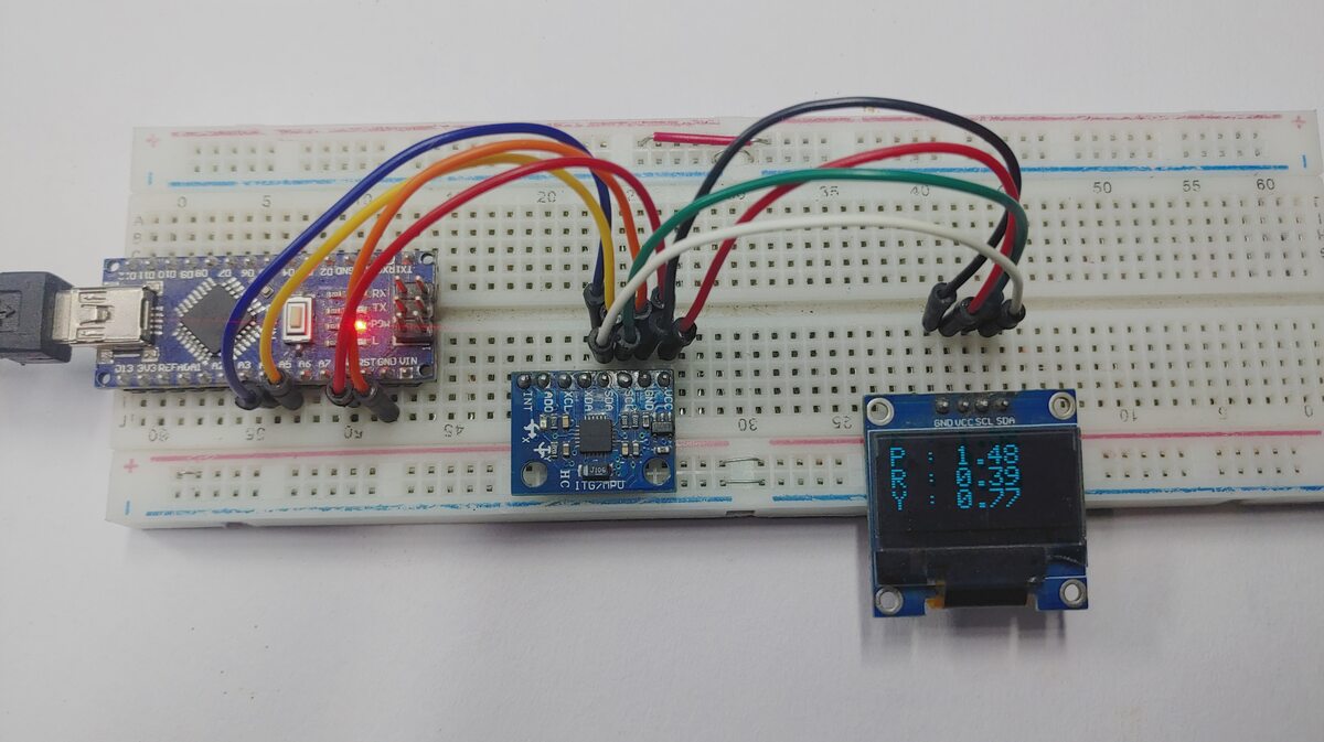
Measure Tilt Angle with MPU6050, Arduino, And Display On OLED
| OLED | Arduino |
|---|---|
| VCC | 3.3 to 5V |
| GND | GND |
| SCL | A5 |
| SDA | A4 |
Source Code for Measure Tilt Angle with MPU6050 & OLED Display
To Display MPU6050 sensor reading in an OLED Display, we need to use the following libraries:
- Adafruit_SSD1306: https://github.com/adafruit/Adafruit_SSD1306
- Adafruit_GFX: https://github.com/adafruit/Adafruit-GFX-Library
|
1 2 3 4 5 6 7 8 9 10 11 12 13 14 15 16 17 18 19 20 21 22 23 24 25 26 27 28 29 30 31 32 33 34 35 36 37 38 39 40 41 42 43 44 45 46 47 48 49 50 51 52 53 |
/* Get tilt angles on X and Y, and rotation angle on Z * Angles are given in degrees, displays on SSD1306 OLED * * License: MIT */ #include <Wire.h> #include <Adafruit_GFX.h> #include <Adafruit_SSD1306.h> #include <MPU6050_light.h> #define SCREEN_WIDTH 128 // OLED display width, in pixels #define SCREEN_HEIGHT 64 // OLED display height, in pixels // Declaration for an SSD1306 display connected to I2C (SDA, SCL pins) Adafruit_SSD1306 display(SCREEN_WIDTH, SCREEN_HEIGHT, &Wire); MPU6050 mpu(Wire); unsigned long timer = 0; void setup() { Serial.begin(115200); // Ensure serial monitor set to this value also if(!display.begin(SSD1306_SWITCHCAPVCC, 0x3C)) // Address 0x3C for most of these displays, if doesn't work try 0x3D { Serial.println(F("SSD1306 allocation failed")); for(;;); // Don't proceed, loop forever } display.setTextSize(1); display.setTextColor(SSD1306_WHITE); // Draw white text display.clearDisplay(); Wire.begin(); mpu.begin(); display.println(F("Calculating gyro offset, do not move MPU6050")); display.display(); mpu.calcGyroOffsets(); // This does the calibration display.setTextSize(2); } void loop() { mpu.update(); if((millis()-timer)>10) // print data every 10ms { display.clearDisplay(); // clear screen display.setCursor(0,0); display.print("P : "); display.println(mpu.getAngleX()); display.print("R : "); display.println(mpu.getAngleY()); display.print("Y : "); display.print(mpu.getAngleZ()); display.display(); // display data timer = millis(); } } |
Working
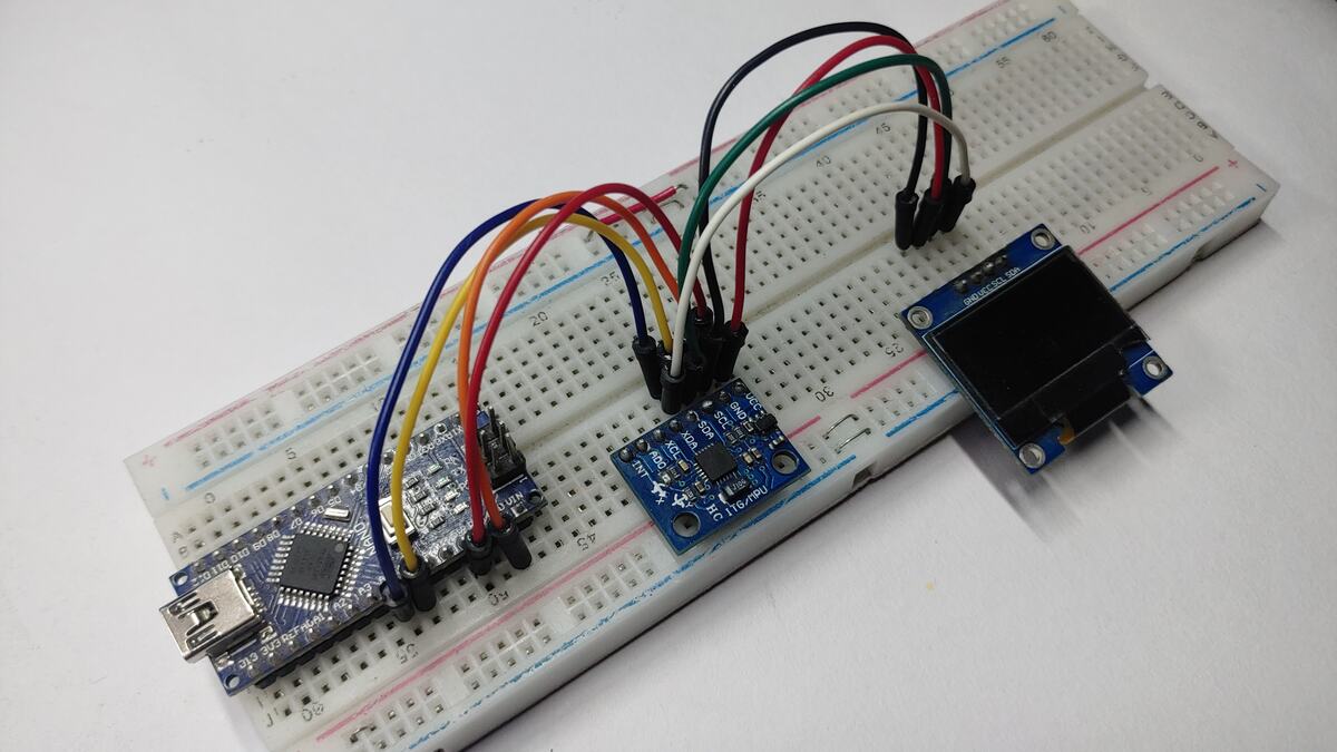
Move the sensor around and watch the readings change.



1 Comment
well written