Introduction
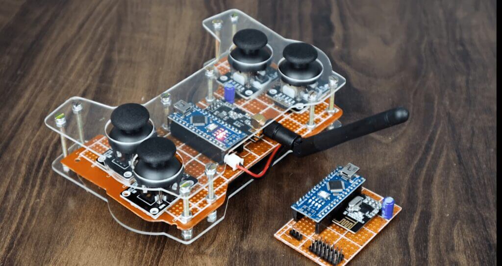
In this tutorial, I will be discussing the Arduino RC transmitter and how it can be used to control remote-controlled vehicles. The Arduino RC transmitter is a device that can be used to control remote-controlled cars, trucks, boats, planes,s and even drones.
Supplies
You will need some basic electronic components, as well as an Arduino board and some software. With this setup, you will be able to control your RC toy with a radio controller.
Components Used
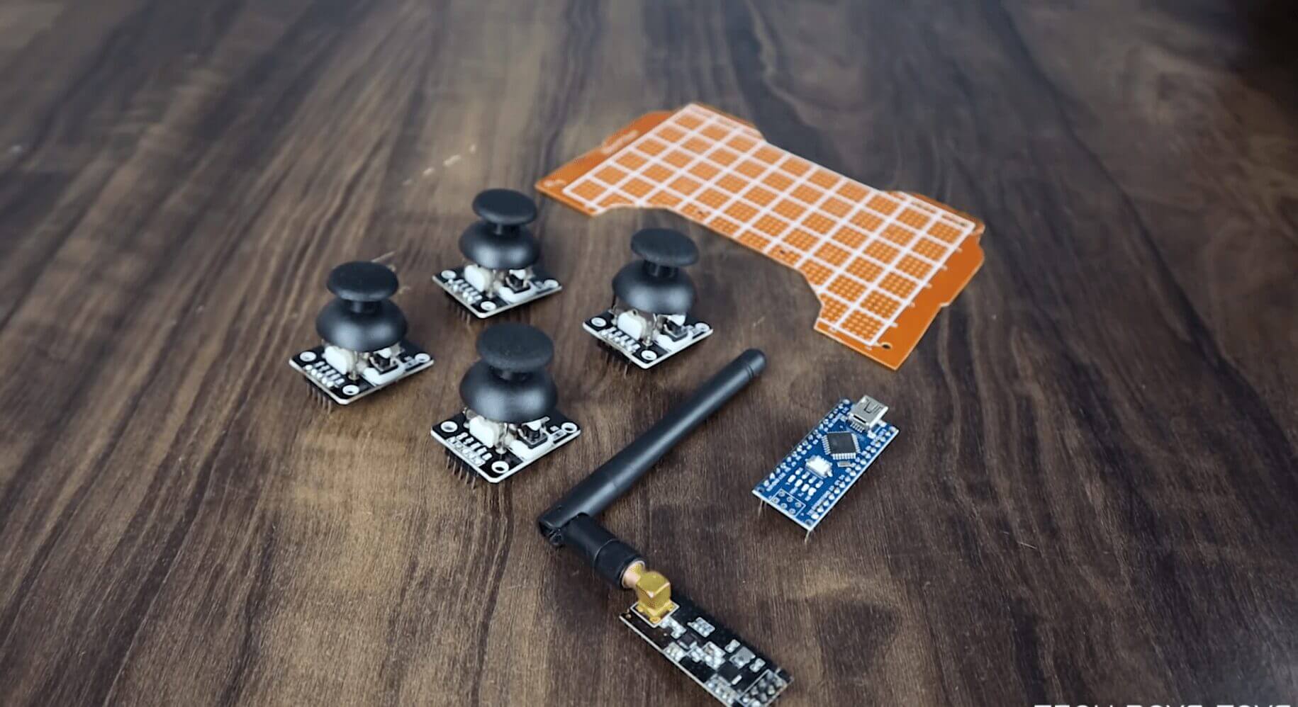
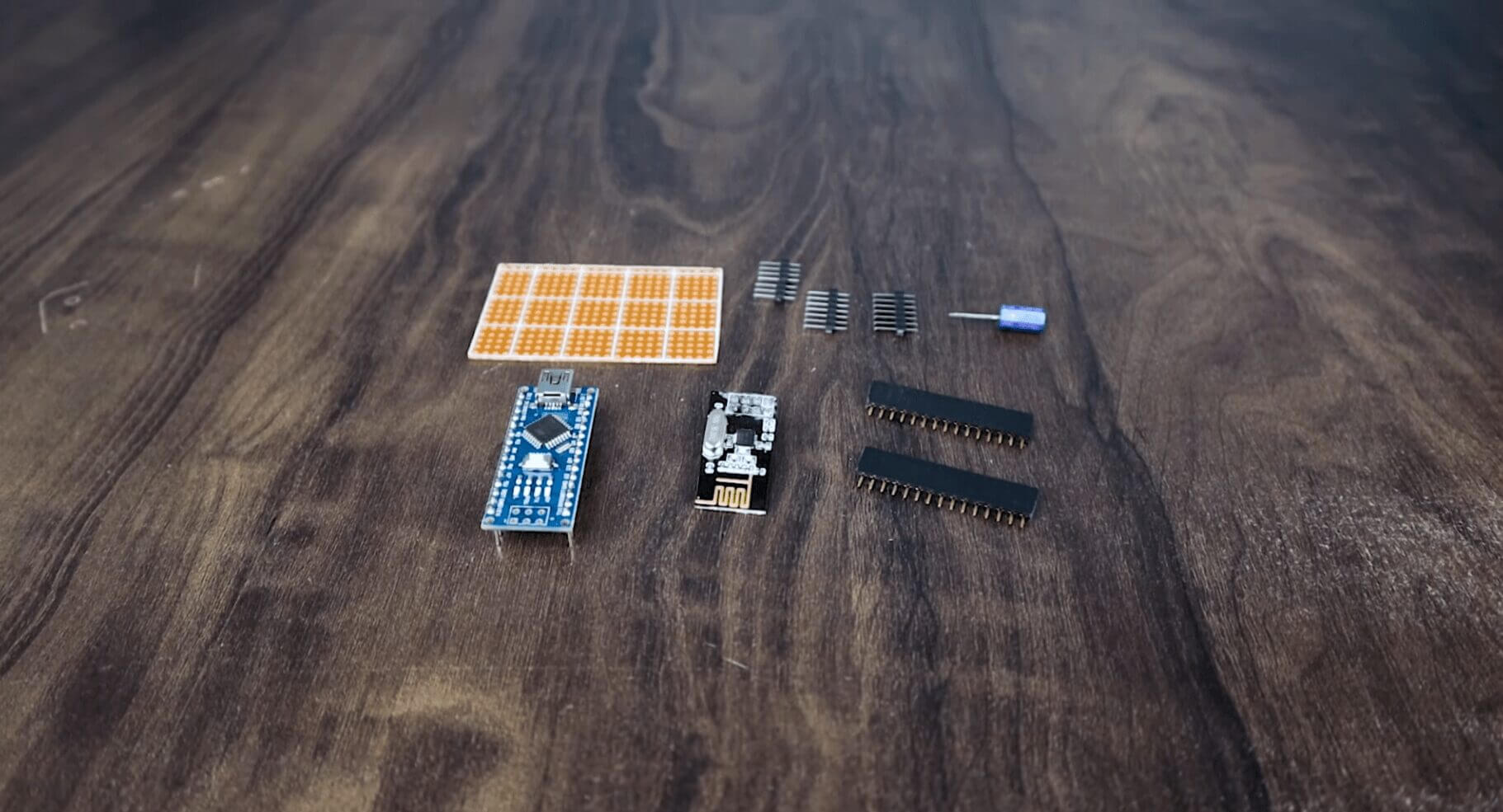
- 2X Arduino Nano: Amazon
- 2X Nrf24l01: Amazon
- 4X JoyStick Module: Amazon
- 2x 100uf/25V Capacitor: Amazon
- 7.4 V Li-Po Battery: Amazon
- 3.7V Li-Ion Battery: Amazon
- Brushless Motor & ESC: Amazon
Tools Used
Disclosure: These are affiliate links. As an Amazon Associate, I earn from qualifying purchases.
What is an Arduino RC transmitter?
It is a simple device that consists of an Arduino board and a radio transmitter. The Arduino board is used to send signals to the radio transmitter, which in turn, controls the remote-controlled vehicle. It allows hobbyists and enthusiasts to build custom remote controllers for their RC projects and enables them to program and customize the transmitter’s functionality.
It can be used to control cars, trucks, boats, and even drones. The transmitter can be used to control the speed, direction, and even the lights of the remote-controlled vehicle.
The benefits of using an Arduino RC transmitter.
Arduino is a popular open-source electronics platform based on easy-to-use hardware and software. It’s a great way to make all kinds of fun and interesting RC toys!
It can be used to control a wide variety of remote-controlled toys. It is a simple device that is easy to use. It is an inexpensive device that can be used by anyone.
The features of an Arduino RC transmitter.
The Arduino RC transmitter has four channels, so you can control two different devices at the same time. The Arduino RC transmitter is powered by two AA batteries, so it’s always ready to go. And when you’re done using it, the transmitter can be easily disconnected from your Arduino and stored away until you’re ready to use it again.
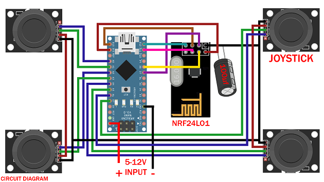
Arduino RC Transmitter Circuit Diagram
The Arduino RC transmitter circuit consists of three main parts: the Arduino, the NRF24L01 transceiver module, and the receiver. The Arduino is the brain of the circuit and is responsible for sending the signal to the transmitter.
The transmitter then broadcasts the signal to the receiver, which decodes the signal and sends it to the proper device. Arduino nano which is powered using 2 LiPo batteries
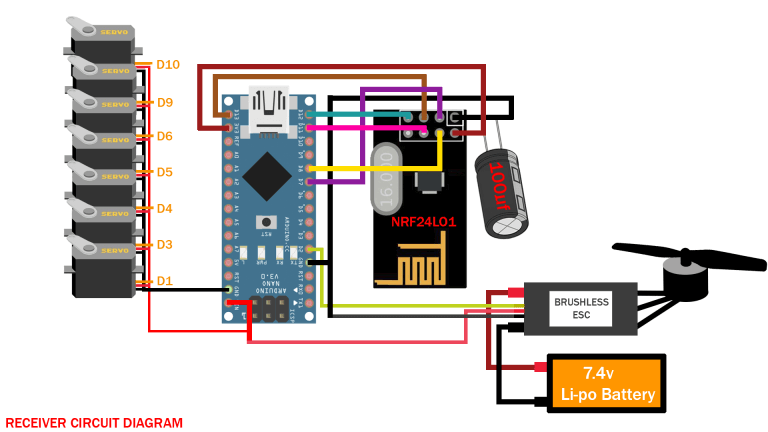
Arduino RC Receiver Circuit Diagram
Making the Circuit
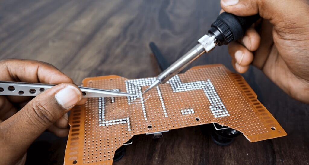
In the previous steps, I have explained the function of each of the components in the circuit. move to solder the components on the prototype board.
The circuit diagram is very straightforward. You have to connect all components with Arduino pins as per the schematic diagram. The schematic diagram is shown above.
- Mounting the Nano: First cut two rows of female header pins with 15 pins in each. Then solder the header pins in Arduino nano. Be sure the distance between the two rails fits the Arduino nano.
- Mounting NRF24l01: Cut a female header with 4pins x2. Then solder it as shown in the picture.
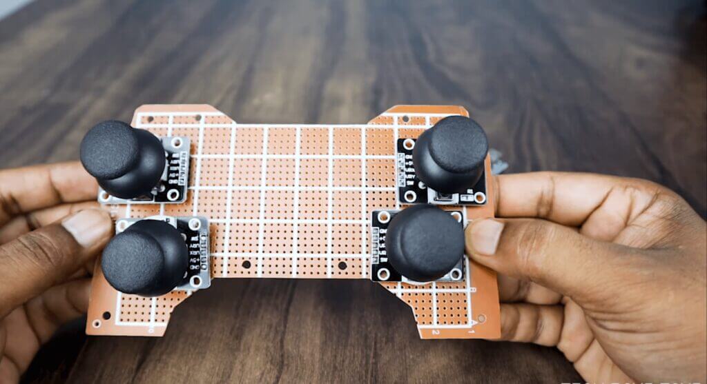
- Mounting the terminals and components: Solder the remaining components as shown in the pictures.
- Wiring: Make the wiring as per the schematic diagram.
Make The Transmitter Module
- Cut header connectors for Arduino nano, NRF24l01 Module (4pins 2nos ), and Power (2 pins).
- Solder the header according to the schematic.
- Place the Arduino nano over the header and connect NRF24l01, joystick.
Prepare the Enclosure
It also gives a better look at the device. Place everything inside
Make Reciever Module
- Solder Arduino nano with zero PCB board
- Place the NRF receiver module on the board.
- solder everything as per schematics diagram
Software & Libraries
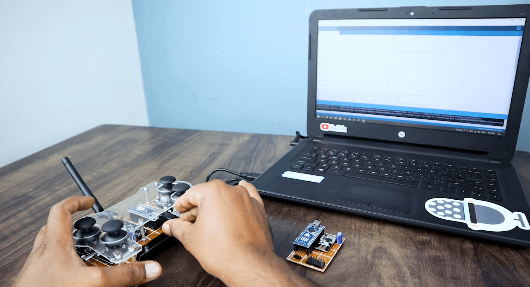
First, download the attached Arduino Code. Then download the following libraries and install them.
Libraries: Download and install the following libraries:
After downloading the library unzip it and installed it with your Arduino Library Manager in
Sketch > Include Library > Manage Libraries…
Source Code
The code I wrote for the Arduino controls the radio module and allows the user to change the frequency of the radio station that is being received.
The code also allows the user to turn the radio on and off, and adjust the volume. The radio I built works well and I have enjoyed using it. It was a fun project to work on, and I learned a lot about electronics in the process. I hope to build more radios in the future, and perhaps even
Software for Transmitter:
Before going to upload the code to the transmitter board, you have to set a few things in the IDE
- Board -> Arduino Nano (what board you have used)
- Serial Port -> COM03 (check the com port in which your device is connected )
After setting the above things, down the code wireless_tx and upload it.
|
1 2 3 4 5 6 7 8 9 10 11 12 13 14 15 16 17 18 19 20 21 22 23 24 25 26 27 28 29 30 31 32 33 34 35 36 37 38 39 40 41 42 43 44 45 46 47 48 49 50 51 52 53 54 55 56 57 58 59 60 61 62 63 64 65 66 67 68 69 70 71 72 |
// 8 Channel Transmitter #include <SPI.h> #include <nRF24L01.h> #include <RF24.h> const uint64_t pipeOut = 0xE9E8F0F0E1LL; //IMPORTANT: The same as in the receiver 0xE9E8F0F0E1LL RF24 radio(7, 8); // select CE,CSN pin | struct Signal { byte throttle_a; byte pitch_a; byte roll_a; byte yaw_a; byte throttle_b; byte pitch_b; byte roll_b; byte yaw_b; }; Signal data; void ResetData() { data.throttle_a = 127; // Motor Stop (254/2=127)(Signal lost position) data.pitch_a = 127; // Center (Signal lost position) data.roll_a = 127; // Center(Signal lost position) data.yaw_a = 127; // Center (Signal lost position ) data.throttle_b = 127; // Center (Signal lost position ) data.pitch_b = 127; // Center (Signal lost position ) data.roll_b = 127; // Center (Signal lost position ) data.yaw_b = 127; // Center (Signal lost position ) } void setup() { //Start everything up radio.begin(); radio.openWritingPipe(pipeOut); radio.stopListening(); //start the radio comunication for Transmitter ResetData(); } // Joystick center and its borders int mapJoystickValues(int val, int lower, int middle, int upper, bool reverse) { val = constrain(val, lower, upper); if ( val < middle ) val = map(val, lower, middle, 0, 128); else val = map(val, middle, upper, 128, 255); return ( reverse ? 255 - val : val ); } void loop() { // Control Stick Calibration // Setting may be required for the correct values of the control levers. data.throttle_a = mapJoystickValues( analogRead(A0), 524, 524, 1015, false ); data.roll_a = mapJoystickValues( analogRead(A1), 12, 524, 1020, true ); // "true" or "false" for servo direction data.pitch_a = mapJoystickValues( analogRead(A2), 12, 524, 1020, true ); // "true" or "false" for servo direction data.yaw_a = mapJoystickValues( analogRead(A3), 12, 524, 1020, true ); // "true" or "false" for servo direction data.throttle_b = mapJoystickValues( analogRead(A4), 12, 524, 1020, true ); // "true" or "false" for servo direction data.roll_b = mapJoystickValues( analogRead(A5), 12, 524, 1020, true ); // "true" or "false" for servo direction data.pitch_b = mapJoystickValues( analogRead(A6), 12, 524, 1020, true ); // "true" or "false" for servo direction data.yaw_b = mapJoystickValues( analogRead(A7), 12, 524, 1020, true ); // "true" or "false" for servo direction radio.write(&data, sizeof(Signal)); } |
Software for Receiver :
Similar to the above set the following for the receiver board
- Board -> Arduino UNO (what board you have used)
- Serial Port -> COM03 (check the com port in which your device is connected)
After setting the above things, down the code wireless_rx and upload it.
|
1 2 3 4 5 6 7 8 9 10 11 12 13 14 15 16 17 18 19 20 21 22 23 24 25 26 27 28 29 30 31 32 33 34 35 36 37 38 39 40 41 42 43 44 45 46 47 48 49 50 51 52 53 54 55 56 57 58 59 60 61 62 63 64 65 66 67 68 69 70 71 72 73 74 75 76 77 78 79 80 81 82 83 84 85 86 87 88 89 90 91 92 93 94 95 96 97 98 99 100 101 102 103 104 105 106 107 108 109 110 111 112 |
// 8 Channel Receiver #include <SPI.h> #include <nRF24L01.h> #include <RF24.h> #include <Servo.h> int ch_width_1 = 0; int ch_width_2 = 0; int ch_width_3 = 0; int ch_width_4 = 0; int ch_width_5 = 0; int ch_width_6 = 0; int ch_width_7 = 0; int ch_width_8 = 0; Servo ch1; Servo ch2; Servo ch3; Servo ch4; Servo ch5; Servo ch6; Servo ch7; Servo ch8; struct Signal { byte throttle_a; byte pitch_a; byte roll_a; byte yaw_a; byte throttle_b; byte pitch_b; byte roll_b; byte yaw_b; }; Signal data; const uint64_t pipeIn = 0xE9E8F0F0E1LL; RF24 radio(7, 8); void ResetData() { // Define the inicial value of each data input. // The middle position for Potenciometers. (254/2=127) data.throttle_a = 127; // Motor Stop data.pitch_a = 127; // Center data.roll_a = 127; // Center data.yaw_a = 127; // Center data.throttle_b = 127; // Center data.pitch_b = 127; // Center data.roll_b = 127; // Center data.yaw_b = 127; // Center } void setup() { //Set the pins for each PWM signal ch1.attach(2); ch2.attach(3); ch3.attach(4); ch4.attach(5); ch5.attach(1); ch6.attach(6); ch7.attach(9); ch8.attach(10); //Configure the NRF24 module ResetData(); radio.begin(); radio.openReadingPipe(1,pipeIn); radio.startListening(); //start the radio comunication for receiver } unsigned long lastRecvTime = 0; void recvData() { while ( radio.available() ) { radio.read(&data, sizeof(Signal)); lastRecvTime = millis(); // receive the data } } void loop() { recvData(); unsigned long now = millis(); if ( now - lastRecvTime > 1000 ) { ResetData(); // Signal lost.. Reset data } ch_width_1 = map(data.throttle_a, 0, 255, 1000, 2000); ch_width_2 = map(data.pitch_a, 0, 255, 1000, 2000); ch_width_3 = map(data.roll_a, 0, 255, 1000, 2000); ch_width_4 = map(data.yaw_a, 0, 255, 1000, 2000); ch_width_5 = map(data.throttle_b, 0, 255, 1000, 2000); ch_width_6 = map(data.pitch_b, 0, 255, 1000, 2000); ch_width_7 = map(data.roll_b, 0, 255, 1000, 2000); ch_width_8 = map(data.yaw_b, 0, 255, 1000, 2000); // Write the PWM signal ch1.writeMicroseconds(ch_width_1); ch2.writeMicroseconds(ch_width_2); ch3.writeMicroseconds(ch_width_3); ch4.writeMicroseconds(ch_width_4); ch5.writeMicroseconds(ch_width_5); ch6.writeMicroseconds(ch_width_6); ch7.writeMicroseconds(ch_width_7); ch8.writeMicroseconds(ch_width_8); } |
Conclusion
The nrf24l01 is a highly versatile radio controller that can be used in a variety of applications. Its small size and low power consumption make it ideal for use in wireless applications where space is at a premium. The nrf24l01 is a 2.4GHz radio transceiver. It has a range of up to 300m and can transmit at speeds up to 2Mbps. The nrf24l01 can be used in a variety of modes, including:
- Stand-alone radio controller
- Wireless remote control
- Wireless data link
- Wireless sensor network
Hope my tutorial is helpful. If you like it, don’t forget to share 🙂
You may also like this :
- Make ESP8266 Drone (This Drone Can Climb on Wall)
- The Ultimate Guide to How To Build a Drone At Home: Guide for Beginners 2022



2 Comments
Pingback: Make Arduino Home automation System Using TV Remote
Pingback: How To Use MCP2515 SPI CAN Bus Module With Arduino - Code