Introduction
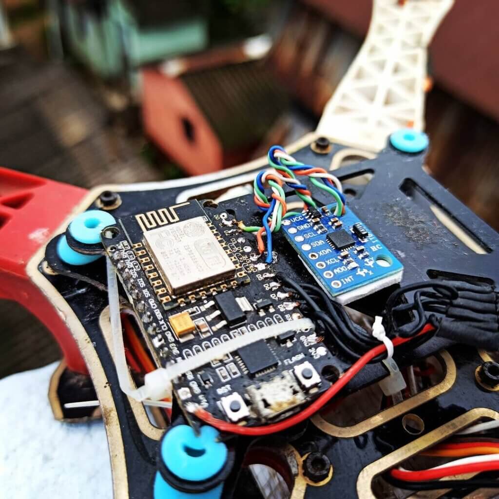
How to make ESP8266 Flight Controller, you are excited by the title! well, I am going to show how I made this Flight controller Using ESP8266.
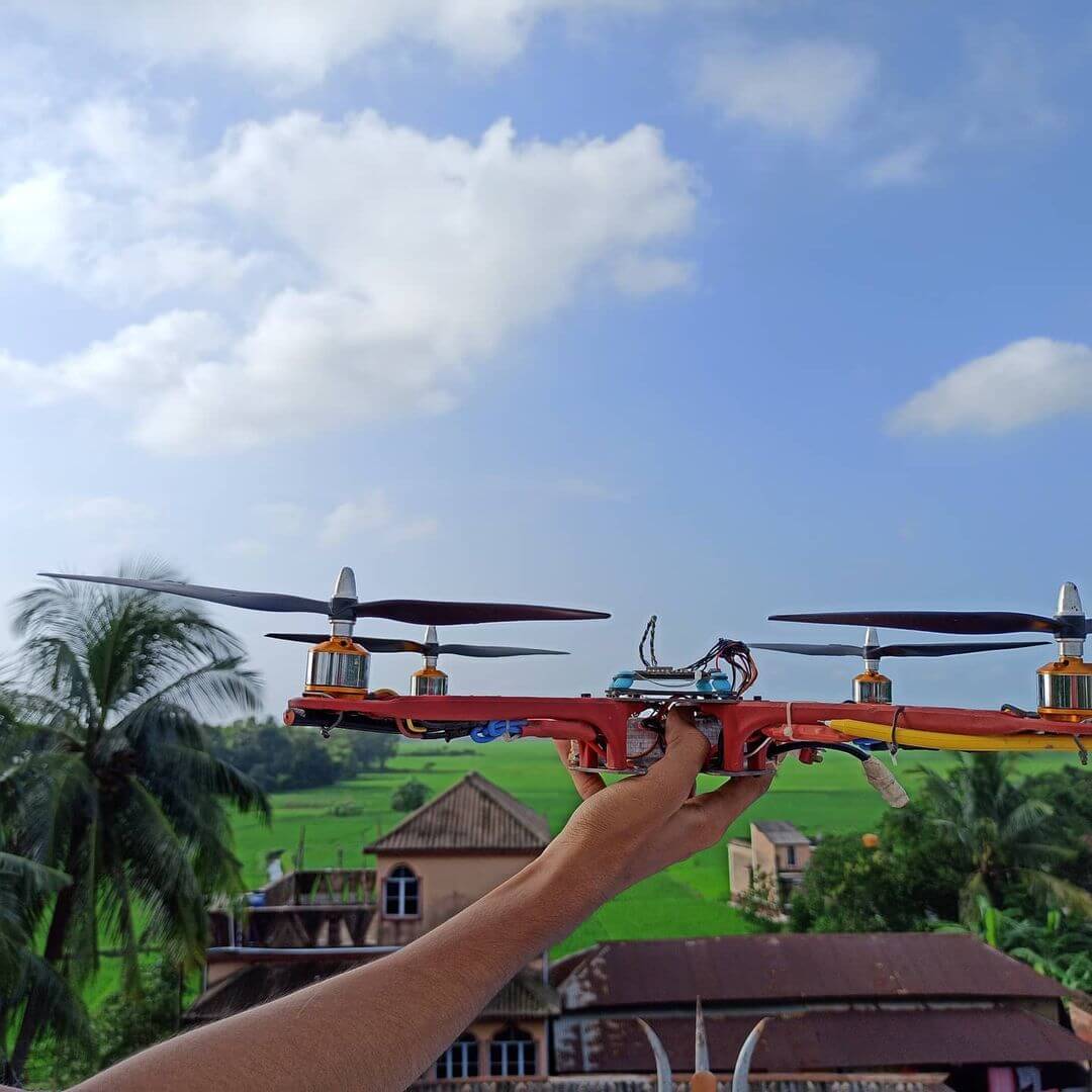
The search to make quadcopters without a flight controller ends here. I was kind of making a drone for my project. For a long time, I’ve dreamt about my own Flight Controller. Yes, I made my own Flight Controller including the best of all the features I’ve upgraded till now. So, let’s break those limitations.
I was making a drone for my project I was thinking to make it without a flight controller as the flight controller goes too expensive so I was surfing the net all night without the flight controller to make it work and it was very disappointing that I didn’t do one. So I decided to make this blog so it’s easier for people who will be making a quadcopter without a flight controller. The Ultimate Guide to How To Build a Drone At Home: Guide for Beginners
Required Material – ESP8266 Flight Controller
🌀 Project Parts ~
- MPU6050 : https://amzn.to/3BhyjZj
- NodeMcu : https://amzn.to/3CpKODd
🌀 Drone Kit ~
- BLDC motor: https://amzn.to/3Eoi1zH
- Props: https://amzn.to/3mlUIQL
- Lipo charger : https://amzn.to/2ZFT8AF
- F450 frame: https://amzn.to/3mnmKvg
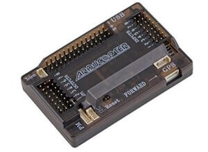
- APM 2.8 : https://amzn.to/3vUAr8k
- ESC: https://amzn.to/3blYzXT
- Remote: https://amzn.to/3bjCSrq
FC (flight controller ) working:
A drone flight controller is a little device that is used to control the flight of a drone. It is generally a small, hand-held device that is used to control the flight of a drone by sending signals to the drone’s motors. The flight controller is the brain of the drone, and it is what allows the drone to be controlled. It is responsible for receiving inputs from the pilot and then sending signals to the drone’s motors to control the flight.
An FC mainly contains 4 segments. The input segment takes instructions from the user on where to move the drone. And the Output segment sends a PWM signal to the ESCs and controls the motor speed in order to fly according to the instructions.
The most common channels are pitch, yaw, and throttle. The pitch channel is used to control the angle of the drone’s nose, and the yaw channel is used to control the direction of the drone’s flight. The throttle channel is used to control the speed of the drone’s motors.
The IMU simply measures the tilt angle in 3 axes. The processing unit collects all data and corrects the tilt angle using the PID controller. We can also include peripherals devices like GPS, and compass. But that would be for another video.
NodeMcu
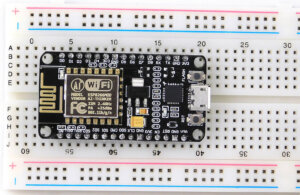
NodeMcu is an open-source IoT platform. It is based on the ESP8266 chip and provides WiFi connectivity. It is very easy to use and can be programmed using the Arduino IDE. NodeMcu is perfect for building IoT applications due to its low cost and ease of use.
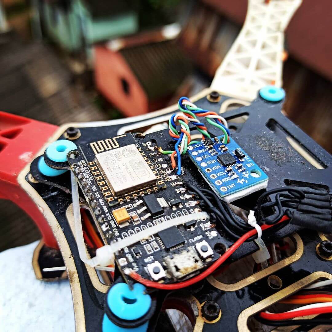
Actually, this little device is way more powerful than I thought. It has WiFi, it runs on 80Mhz and it has an inbuilt floating point processor so that’s quite awesome For the IMU I’m gonna use MPU6050. It comes with a gyroscope and an accelerometer sensor. Here I’m not using any Tx Rx, I will use WiFi for communication
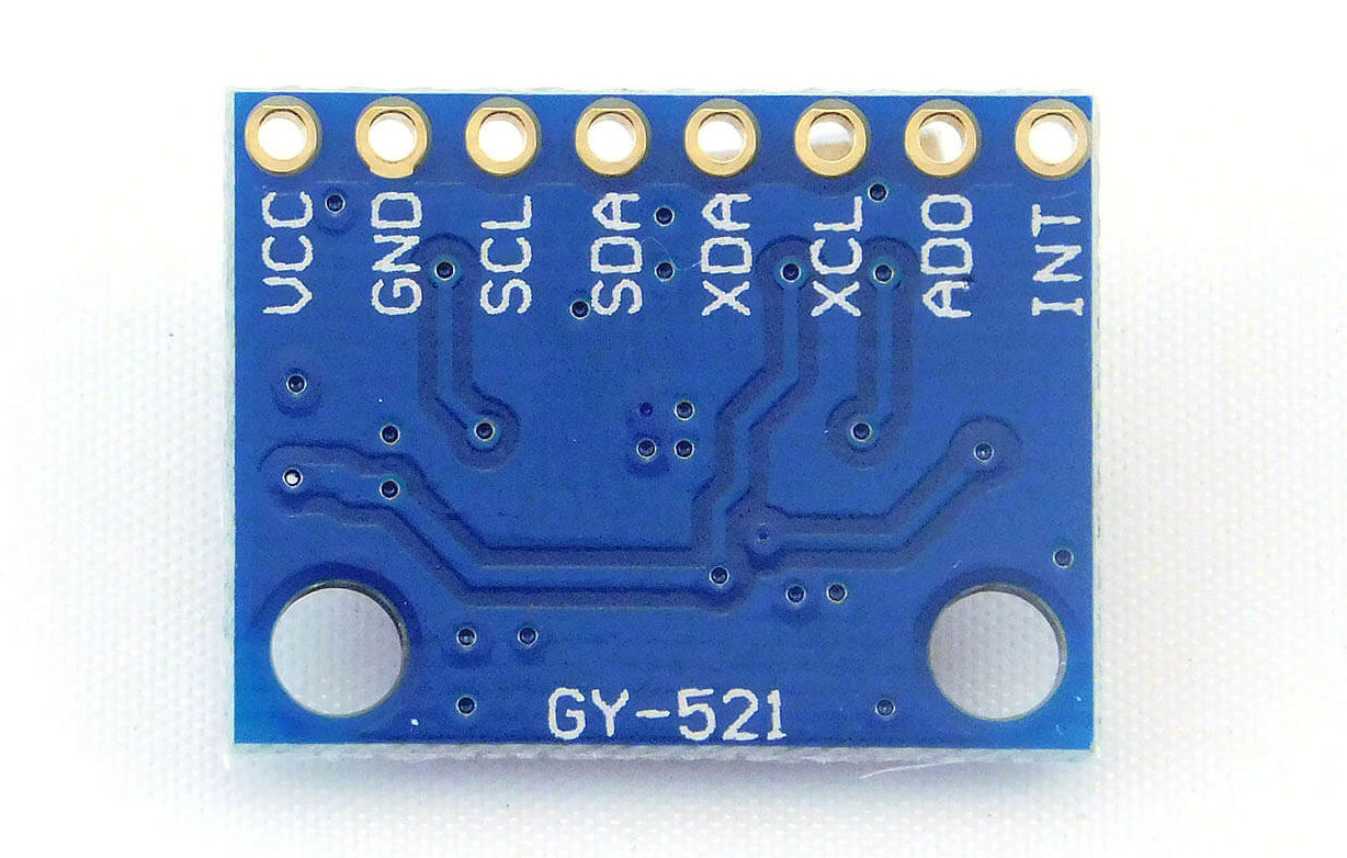
MPU6050
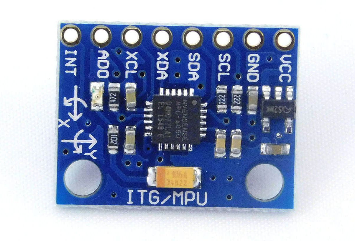
The MPU6050 is a six-axis gyroscope and accelerometer in a single chip. It is used in mobile devices, gaming controllers, drones, and other applications where reliable motion sensing is required. It’s relatively inexpensive and easy to use, making it a popular choice for many projects.
This sensor uses i2c to communicate. So I connected SDA & SCL to D1 and D2 of the NodeMCU. As described in the datasheet it has 3 modes for each sensor.
I’m gonna use a 500-degree scale range for the gyroscope and an 8-g scale range for the accelerometer. To get the angles from it I have to configure these registers. The Wire library of Arduino IDE will easily do this job then it requests 14 bytes from the sensor and read the angles in series.
Make sure that you have defined the integers as 16 bits as the data is a 2’s complement value. The accelerometer provides real-time angle But the gyroscope provides angular velocity. If I want to get the angle from the gyroscope then I have to integrate the angular velocity in each loop.
So, I got angles from 2 different sensors. Well, the motors generate a lot of vibrations which will significantly affect the accelerometer. So I’ve used a complimentary filter to overcome this problem. Which uses both sensor data to generate a stable angle.
But the gyro sensors have few errors. To get it solved I place the drone level and read the data 4000 times then took the average and I got gyro errors.
In this way, I can calibrate it once and use it every time. Then I subtracted it in each loop. So, now I get the perfect real-time angles.
PWM & ESC
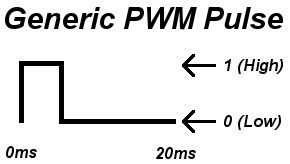
Pulse Width Modulation (PWM) and Electronic Speed Control (ESC) are two common methods used to control the speed of motors. PWM is a type of modulation where the width of the pulse is varied to control the speed of the motor.
ESC is a type of electronic speed control that uses electronic signals to control the speed of the motor. PWM is commonly used in RC applications to control the speed of brushed motors.
Before getting into the ESCs we need to know about PWM. PWM is a method of producing a pulse of the HIGH & LOW states of a pin. The data transferred through it is the time between the rising edge and the falling edge of the pulse and it is refreshed periodically. Which is the frequency of the PWM signal. Check more how-brushless-motor-and-ESC-work
Then pull down each of the 4 pins connected to the ESC according to the throttle to be sent to the ESCs. In this portion, we got 600 microseconds so I can put other codes here.
And still, the refresh rate will be 2000 microseconds giving us a PWM frequency of 500Hz.
PID
PID, or Proportional Integral Derivative controllers, are a type of feedback control system. PID controllers are commonly used in industrial control applications such as temperature control, speed control, and pressure control.
So, now we can control the speed of individual motors. But to sync it with the angle in order to correct the tilt angles I’m gonna use the PID controller. It uses three types of controllers. The PID controller changes its value proportional to the angle using some formula.
The more you tilt the drone the more it will increase and will reduce if the tilt angle decreases. But only with it, the drone will be wobbly. Something like this. So we need some braking system. And here the D controller comes into place.
In order to fly a drone, the pilot must first calibrate the flight controller. This is done by setting the trim for each channel. The trim is the point at which the drone is level, and it is used to ensure that the drone is level when it is flying. Once the flight controller is calibrated, the pilot can then start flying the drone. To do this, the pilot will use the throttle channel to increase or decrease the speed of the drone’s motors. The pitch channel is used to control the angle of the Drone.
Circuit Diagram – ESP8266 Flight Controller
we’ll be making a circuit diagram for an ESP8266 flight controller. This guide will go over the basics of circuit diagrams and how to create one for your flight controller.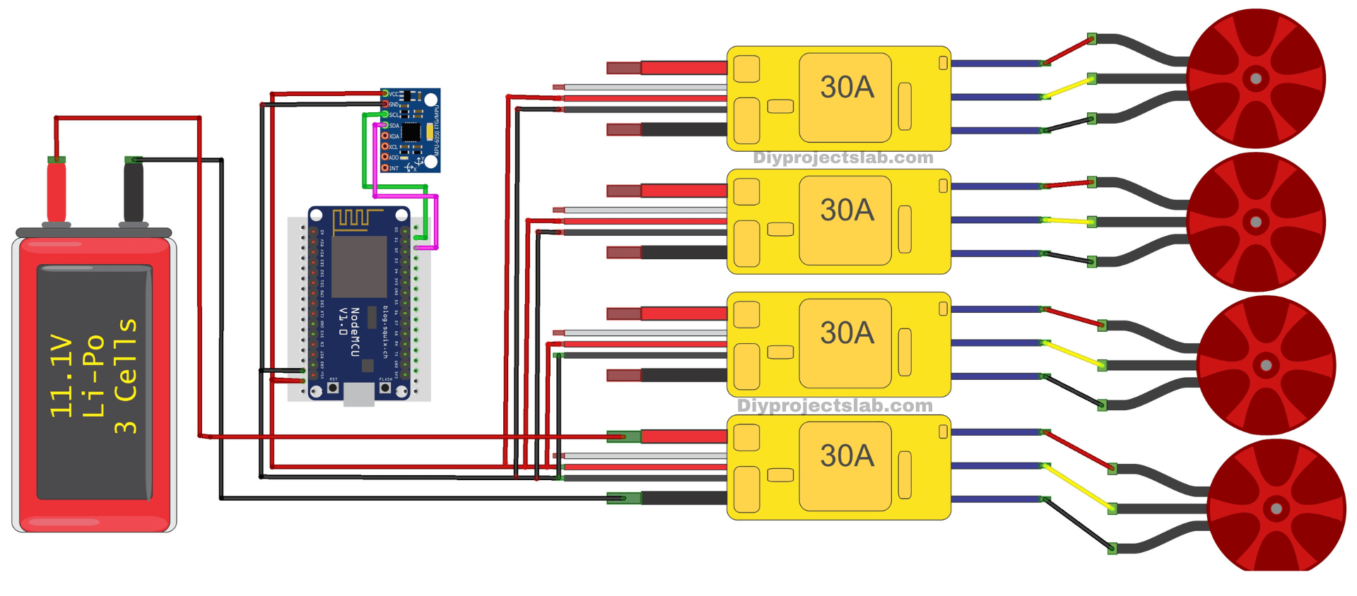
Make the Circuit
Software and Libraries
First, download the Arduino sketch and installed all the libraries. Download and Install the following Libraries:
- ESP8266WiFi.h
Plugin the USB cable into the NODEMCU with your laptop or desktop PC. Set the correct board and COM Port number and upload the code into the ESP8266.
Source Code
|
1 2 3 4 5 6 7 8 9 10 11 12 13 14 15 16 17 18 19 20 21 22 23 24 25 26 27 28 29 30 31 32 33 34 35 36 37 38 39 40 41 42 43 44 45 46 47 48 49 50 51 52 53 54 55 56 57 58 59 60 61 62 63 64 65 66 67 68 69 70 71 72 73 74 75 76 77 78 79 80 81 82 83 84 85 86 87 88 89 90 91 92 93 94 95 96 97 98 99 100 101 102 103 104 105 106 107 108 109 110 111 112 113 114 115 116 117 118 119 120 121 122 123 124 125 126 127 128 129 130 131 132 133 134 135 136 137 138 139 140 141 142 143 144 145 146 147 148 149 150 151 152 153 154 155 156 157 158 159 160 161 162 163 164 165 166 167 168 169 170 171 172 173 174 175 176 177 178 179 180 181 182 183 184 185 186 187 188 189 190 191 192 193 194 195 196 197 198 199 200 201 202 203 204 205 206 207 208 209 210 211 212 213 214 215 216 217 218 219 220 221 222 223 224 225 226 227 228 229 230 231 232 233 234 235 236 237 238 239 240 241 242 243 244 245 246 247 248 249 250 251 252 253 254 255 256 257 258 259 260 261 262 263 264 265 266 267 268 269 |
#include<Wire.h> #include <ESP8266WiFi.h> #include <WiFiUdp.h> WiFiUDP UDP; char packet[7]; boolean recvState; //-----------------------------------------------------------------------// int ESCout_1 ,ESCout_2 ,ESCout_3 ,ESCout_4; int input_PITCH = 50; int input_ROLL = 50; int input_YAW; int input_THROTTLE=1100; int state1,state2,state3,state4; //-----------------------------------------------------------------------// int16_t gyro_x, gyro_y, gyro_z, acc_x, acc_y, acc_z, temperature, acc_total_vector; float angle_pitch, angle_roll, angle_yaw; boolean set_gyro_angles; float angle_roll_acc, angle_pitch_acc; float angle_pitch_output, angle_roll_output; float elapsedTime; long Time, timePrev, time2; long gyro_x_cal, gyro_y_cal, gyro_z_cal; //-----------------------------------------------------------------------// float pitch_PID,roll_PID,yaw_PID; float roll_error, roll_previous_error, pitch_error, pitch_previous_error, yaw_error; float roll_pid_p, roll_pid_d, roll_pid_i, pitch_pid_p, pitch_pid_i, pitch_pid_d, yaw_pid_p, yaw_pid_i; float roll_desired_angle, pitch_desired_angle, yaw_desired_angle; double twoX_kp=5; double twoX_ki=0.003; double twoX_kd=2; double yaw_kp=3; double yaw_ki=0.002; //-----------------------------------------------------------------------// void setup() { pinMode(D5,OUTPUT);pinMode(D6,OUTPUT);pinMode(D7,OUTPUT);pinMode(D8,OUTPUT); delay(1300); Serial.begin(115200); WiFi.mode(WIFI_STA); WiFi.begin("Laptop", "lppasspi"); while (WiFi.status() != WL_CONNECTED){ GPOS = (1 << 14);GPOS = (1 << 12);GPOS = (1 << 13);GPOS = (1 << 15); delayMicroseconds(1000); GPOC = (1 << 14);GPOC = (1 << 12);GPOC = (1 << 13);GPOC = (1 << 15); delayMicroseconds(1000); yield(); } Serial.println(WiFi.localIP()); UDP.begin(9999); //-----------------------------------------------------------------------// Wire.begin(); Wire.setClock(400000); Wire.beginTransmission(0x68); Wire.write(0x6B); Wire.write(0x00); Wire.endTransmission(); Wire.beginTransmission(0x68); Wire.write(0x1C); Wire.write(0x10); Wire.endTransmission(); Wire.beginTransmission(0x68); Wire.write(0x1B); Wire.write(0x08); Wire.endTransmission(); delay(1000); for (int cal_int = 0; cal_int < 2000 ; cal_int ++){ if(cal_int % 125 == 0)Serial.print("."); Wire.beginTransmission(0x68); Wire.write(0x3B); Wire.endTransmission(); Wire.requestFrom(0x68,14); while(Wire.available() < 14); acc_x = Wire.read()<<8|Wire.read(); acc_y = Wire.read()<<8|Wire.read(); acc_z = Wire.read()<<8|Wire.read(); temperature = Wire.read()<<8|Wire.read(); gyro_x = Wire.read()<<8|Wire.read(); gyro_y = Wire.read()<<8|Wire.read(); gyro_z = Wire.read()<<8|Wire.read(); gyro_x_cal += gyro_x; gyro_y_cal += gyro_y; gyro_z_cal += gyro_z; GPOS = (1 << 14);GPOS = (1 << 12);GPOS = (1 << 13);GPOS = (1 << 15); delayMicroseconds(1000); GPOC = (1 << 14);GPOC = (1 << 12);GPOC = (1 << 13);GPOC = (1 << 15); delayMicroseconds(1000); yield(); } gyro_x_cal /= 2000; gyro_y_cal /= 2000; gyro_z_cal /= 2000; //-----------------------------------------------------------------------// Time = micros(); } void loop(){ GPOS = (1 << 14);GPOS = (1 << 12);GPOS = (1 << 13);GPOS = (1 << 15); timePrev = Time; Time = micros(); elapsedTime = (float)(Time - timePrev) / (float)1000000; Wire.beginTransmission(0x68); Wire.write(0x3B); Wire.endTransmission(); Wire.requestFrom(0x68,14); while(Wire.available() < 14); acc_x = Wire.read()<<8|Wire.read(); acc_y = Wire.read()<<8|Wire.read(); acc_z = Wire.read()<<8|Wire.read(); temperature = Wire.read()<<8|Wire.read(); gyro_x = Wire.read()<<8|Wire.read(); gyro_y = Wire.read()<<8|Wire.read(); gyro_z = Wire.read()<<8|Wire.read(); gyro_x -= gyro_x_cal; gyro_y -= gyro_y_cal; gyro_z -= gyro_z_cal; angle_pitch += gyro_x * elapsedTime * 0.01526717557; angle_roll += gyro_y * elapsedTime * 0.01526717557; angle_yaw += gyro_z * elapsedTime * 0.01526717557; angle_pitch += angle_roll * sin(gyro_z * 0.000001066); angle_roll -= angle_pitch * sin(gyro_z * 0.000001066); acc_total_vector = sqrt((acc_x*acc_x)+(acc_y*acc_y)+(acc_z*acc_z)); angle_pitch_acc = asin((float)acc_y/acc_total_vector)* 57.296; angle_roll_acc = asin((float)acc_x/acc_total_vector)* -57.296; angle_pitch_acc += 0; angle_roll_acc += 0; if(set_gyro_angles){ angle_pitch = angle_pitch * 0.9996 + angle_pitch_acc * 0.0004; angle_roll = angle_roll * 0.9996 + angle_roll_acc * 0.0004; } else{ angle_pitch = angle_pitch_acc; angle_roll = angle_roll_acc; set_gyro_angles = true; } angle_pitch_output = angle_pitch_output * 0.9 + angle_pitch * 0.1; angle_roll_output = angle_roll_output * 0.9 + angle_roll * 0.1; //-----------------------------------------------------------------------// roll_desired_angle = 3*((float)input_ROLL/(float)10 - (float)5); pitch_desired_angle =3*((float)input_PITCH/(float)10 - (float)5); //yaw_desired_angle =0; roll_error = angle_roll_output - roll_desired_angle; pitch_error = angle_pitch_output - pitch_desired_angle; yaw_error = angle_yaw - yaw_desired_angle; roll_pid_p = twoX_kp*roll_error; pitch_pid_p = twoX_kp*pitch_error; yaw_pid_p = yaw_kp*yaw_error; if(-3 < roll_error <3){roll_pid_i = roll_pid_i+(twoX_ki*roll_error);} if(-3 < pitch_error <3){pitch_pid_i = pitch_pid_i+(twoX_ki*pitch_error);} if(-3 < yaw_error <3){yaw_pid_i = yaw_pid_i+(yaw_ki*yaw_error);} roll_pid_d = twoX_kd*((roll_error - roll_previous_error)/elapsedTime); pitch_pid_d = twoX_kd*((pitch_error - pitch_previous_error)/elapsedTime); roll_PID = roll_pid_p + roll_pid_i + roll_pid_d; pitch_PID = pitch_pid_p + pitch_pid_i + pitch_pid_d; yaw_PID = yaw_pid_p + yaw_pid_i; if(roll_PID < -400){roll_PID=-400;} else if(roll_PID > 400) {roll_PID=400;} if(pitch_PID < -400){pitch_PID=-400;} else if(pitch_PID > 400) {pitch_PID=400;} if(yaw_PID < -400){yaw_PID=-400;} else if(yaw_PID > 400) {yaw_PID=400;} ESCout_1 = input_THROTTLE - roll_PID - pitch_PID - yaw_PID; ESCout_2 = input_THROTTLE + roll_PID - pitch_PID + yaw_PID; ESCout_3 = input_THROTTLE + roll_PID + pitch_PID - yaw_PID; ESCout_4 = input_THROTTLE - roll_PID + pitch_PID + yaw_PID; if(ESCout_1>2000) ESCout_1=2000; else if(ESCout_1<1100) ESCout_1=1100; if(ESCout_2>2000) ESCout_2=2000; else if(ESCout_2<1100) ESCout_2=1100; if(ESCout_3>2000) ESCout_3=2000; else if(ESCout_3<1100) ESCout_3=1100; if(ESCout_4>2000) ESCout_4=2000; else if(ESCout_4<1100) ESCout_4=1100; roll_previous_error = roll_error; pitch_previous_error = pitch_error; //-----------------------------------------------------------------------// while((micros() - Time) < 1000); state1 = 1; state2 = 1; state3 = 1; state4 = 1; while(state1 == 1 || state2 == 1 || state3 == 1 || state4 == 1){ time2 = micros(); if((time2 - Time) >= ESCout_1 && state1 == 1){ GPOC = (1 << 14); state1=0;} if((time2 - Time) >= ESCout_2 && state2 == 1){ GPOC = (1 << 12);state2=0;} if((time2 - Time) >= ESCout_3 && state3 == 1){ GPOC = (1 << 13);state3=0;} if((time2 - Time) >= ESCout_4 && state4 == 1){ GPOC = (1 << 15);state4=0;} } //-----------------------------------------------------------------------// if(!recvState){ int packetSize = UDP.parsePacket(); if (packetSize) { int len = UDP.read(packet, 6); packet[len] = '\0'; if(String(packet[0]) == "a"){ input_ROLL = int(packet[1]); input_PITCH = int(packet[2]); input_THROTTLE = 1000 + int(packet[3]); input_YAW = int(packet[4]); } else if(String(packet[0]) == "b"){ input_ROLL = int(packet[1]); input_PITCH = int(packet[2]); input_THROTTLE = 1000 + int(packet[3])*100 + int(packet[4]); input_YAW = int(packet[5]); } if(String(packet[0]) == "1"){ twoX_kp = (float)int(packet[1])/(float)100; twoX_ki = (float)int(packet[2])/(float)1000; twoX_kd = (float)int(packet[3])/(float)100; } else if(String(packet[0]) == "2"){ twoX_kp = (float)(float)(int(packet[1])*100 + int(packet[2]))/(float)100; twoX_ki = (float)(float)(int(packet[3])*100 + int(packet[4]))/(float)1000; twoX_kd = (float)(float)(int(packet[5])*100 + int(packet[6]))/(float)100; } else if(String(packet[0]) == "3"){ twoX_kp = (float)(int(packet[1])*100 + int(packet[2]))/(float)100; twoX_ki = (float)int(packet[3])/(float)1000; twoX_kd = (float)int(packet[4])/(float)100; } else if(String(packet[0]) == "4"){ twoX_kp = (float)int(packet[1])/(float)100; twoX_ki = (float)(int(packet[2])*100 + int(packet[3]))/(float)1000; twoX_kd = (float)int(packet[4])/(float)100; } else if(String(packet[0]) == "5"){ twoX_kp = (float)int(packet[1])/(float)100; twoX_ki = (float)int(packet[2])/(float)1000; twoX_kd = (float)(int(packet[3])*100 + int(packet[4]))/(float)100; } else if(String(packet[0]) == "6"){ twoX_kp = (float)(int(packet[1])*100 + int(packet[2]))/(float)100; twoX_ki = (float)(int(packet[3])*100 + int(packet[4]))/(float)1000; twoX_kd = (float)int(packet[5])/(float)100; } else if(String(packet[0]) == "7"){ twoX_kp = (float)int(packet[1])/(float)100; twoX_ki = (float)(int(packet[2])*100 + int(packet[3]))/(float)1000; twoX_kd = (float)(int(packet[4])*100 + int(packet[5]))/(float)100; } else if(String(packet[0]) == "8"){ twoX_kp = (float)(int(packet[1])*100 + int(packet[2]))/(float)100; twoX_ki = (float)int(packet[3])/(float)1000; twoX_kd = (float)(int(packet[4])*100 + int(packet[5]))/(float)100; } Serial.print(input_ROLL);Serial.print(" "); Serial.print(input_THROTTLE);Serial.print(" "); Serial.print(twoX_kp);Serial.print(" "); Serial.print(twoX_ki,3);Serial.print(" "); Serial.print(twoX_kd);Serial.println(); } } else if(recvState){ UDP.beginPacket(UDP.remoteIP(), UDP.remotePort()); UDP.print(Time - timePrev); UDP.endPacket(); } recvState = !recvState; //-----------------------------------------------------------------------// Serial.print(angle_roll_output);Serial.print(" "); Serial.print(angle_pitch_output);Serial.print(" | "); Serial.print(roll_desired_angle);Serial.print(" "); Serial.print(pitch_desired_angle); Serial.println(); } |
Click here for the full code and diagram on the GitHub page NodeMCU-FlightController-MPU6050
Video Tutorial:
Similar Post
- Build Obstacle Avoidance Drone Using Arduino
- Make ESP8266 Drone (This Drone Can Climb on Wall)
- Important Parts Of A Drone – Every Component Explained
- The Ultimate Guide to How To Build a Drone At Home: Guide for Beginners
- Make Arduino RC transmitter For RC Toys – Drone or Plane

