Introduction
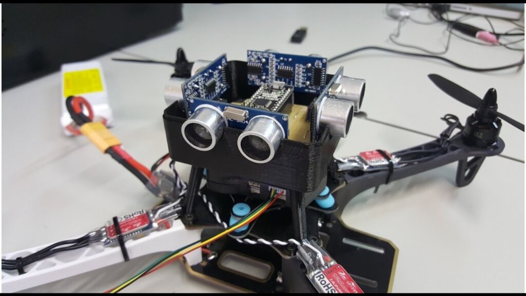
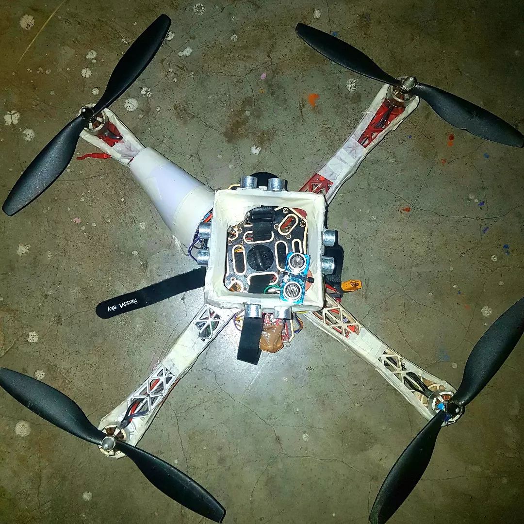
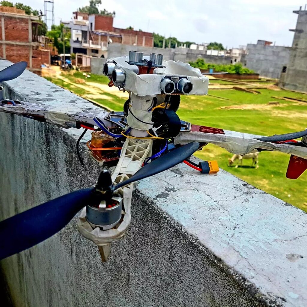
In this reader, we will be discussing how to build an obstacle-avoidance drone using Arduino. This can be a useful skill to have if you are looking to get into the drone-building hobby, or if you simply want to create a drone that can avoid obstacles. This drone will use an ultrasonic sensor to detect obstacles in its path.
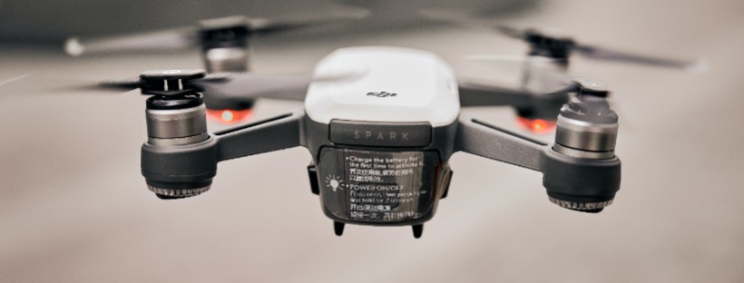
The trend of technological advancement has led to the development of some amazing devices and gadgets. The use of these devices and gadgets has made our lives easier and better. One such amazing device is the drone
Thank You NextPCB:
This project is successfully finished because of the help and sponsorship from NextPCB. Guys if you have a PCB project, please visit their website and get exciting discounts and coupons and more.
- Only 0$ for 5-10pcs PCB Prototypes:Nextpcb.com/pcbprototype
- Register and get $100 from NextPCB: Nextpcb.com/coupon
Why NextPCB
- Most Efficient, Economic, Inventive PCB Solutions
- Higher Quality
- Lower Price
- Faster Delivery
Drones are unmanned aircraft that can be controlled remotely. They are mainly used for aerial photography and videography. However, they can also be used for other purposes such as surveillance, delivery, and search and rescue operations. Drones are becoming increasingly popular and are being used for various purposes. However, one of the main issues with drones is that they can sometimes collide with obstacles while in flight.
This can damage the drone and also pose a danger to people and property. One way to avoid collisions is to use obstacle avoidance sensors. These sensors can detect obstacles in the path of the drone and send a signal to the drone to change its course. This would help to avoid collisions and make drones safer to use.
In this project, we will be building a drone that can avoid obstacles using Arduino. We will be using infrared sensors to detect obstacles and a buzzer to indicate when an obstacle is present. The drone will be programmed to fly around an obstacle when it is detected. This project is perfect for beginners who are interested in learning about drones and programming. It is also a great project for those who want to build a drone that can be used for practical purposes. So, let’s get started! The Ultimate Guide to How To Build a Drone At Home: Guide for Beginners 2022
Parts and Tools Required – Arduino Drone
Collect the Components Before you start, you’ll need to gather all of the components for this drone. We’ll be using the following: –
🌀 Parts Used :
You can find all components on amazon.com
🌀 Drone Kit ~ for Build a Drone
- Motors https://amzn.to/36Zb8tK
- ESCs (Electronic Speed Controllers) https://amzn.to/3jhDimd
- Frame https://amzn.to/3jjJ6LJ
- Receiver https://amzn.to/3xbG9Fm
- Transmitter https://amzn.to/3xbG9Fm
- Flight Controller https://amzn.to/3DTNhaO
- Propellers https://amzn.to/3jmAd4e
- Battery https://amzn.to/3DTNGdk
Here’s how it works:
The Ultrasonic sensor measures the distance between the sensor itself and the object and transmits it to the Arduino in the form of the analogue signal (value range: 0 to 1023). We should make a setpoint say 35cm from the Ultrasonic sensor so if the setpoint reaches below 35cm the PID algorithm in the Arduino will start its work by sending out the correction value to the stabilization board.
Most of you understand what PPM and PWM signals are and how it is used in the RC heavens and this is how it is used in our project.
Pulse width modulation (PWM) is a type of modulation where the width of the pulse is varied to encode information. The width of the pulse is proportional to the amplitude of the signal. Pulse width modulation is commonly used in control systems where it is used to control the speed of a motor or the brightness of a light.
RC Devices that use PWM Pulses:
- Servos
- Electronic Speed Controllers
- R/C receivers
- Data loggers
- Autopilot/Stabilization systems
- Servo Controller
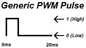
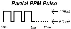
Pulse position modulation (PPM) is a type of modulation where the position of the pulse is varied to encode information. The position of the pulse is proportional to the amplitude of the signal. Pulse position modulation is commonly used in communication systems where it is used to encode information in a signal. PWM and PPM Difference and Conversion
RC Devices that use PPM Pulses:
- R/C transmitters
- R/C receivers
- Autopilot/Stabilization systems
- PCTx
The Drone contains Five basic components:
1x Arduino Nano. It is the brain of our drone and where the flight control software will run
1x Ultrasonic Sensor HC-SR04. HC-SR04 ultrasonic sensor to measure distances with a measurement error of less than 0.5cm aimed at estimating the flight altitude of our drone
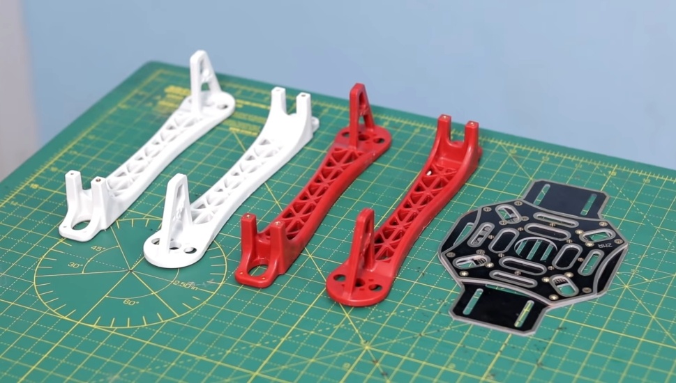
1x Frame 450. It is the structure where we will mount all the hardware components of our drone. We are going to use a 450mm frame :
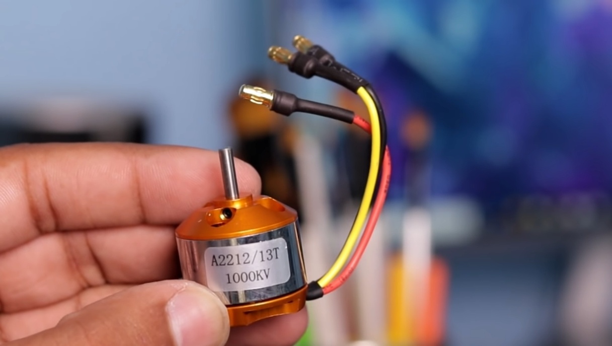
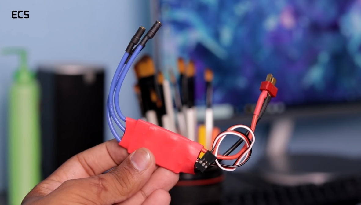
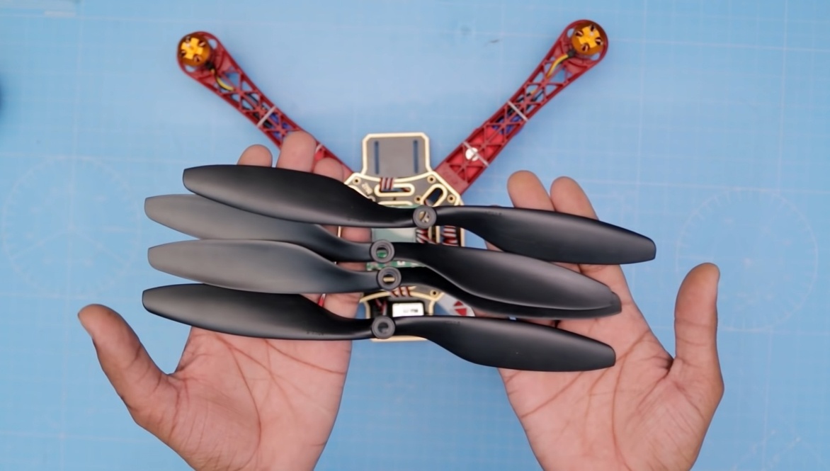
4x 1000kV motors and 4x 20Amp ESC . One of the most important components of our drone is the motors and the 4 ESCs in charge of making them rotate. We will use 1000kV motors and ESC of at least 20 amps. Make sure that the pack you buy also includes the propellers.
1x Remote control and RC receiver. We will use it to control the drone and make it move as we please. There are countless models available, I leave you the one I use, whose characteristics are sufficient for this application. Make sure that the model you buy also includes the receiver.
1x 3S 5000mAh battery. Drone power source. We will use a 5000mAh 3S battery.
Assembly of the components
we’ll show you how to assemble a quadcopter using an Arduino flight controller. We’ll also go over how to program the Arduino to make the drone fly. It requires a good understanding of electronics and programming. We’ll be using the Arduino IDE to program the Arduino, so if you’ve never used Arduino before, check out our getting started guide.
Wiring Diagram – Obstacle Avoidance Drone
The wiring diagram is absolutely straightforward. You have to connect the Ultrasonic sensor module pins with Arduino pins as per the schematic diagram. The schematic diagram is shown below.
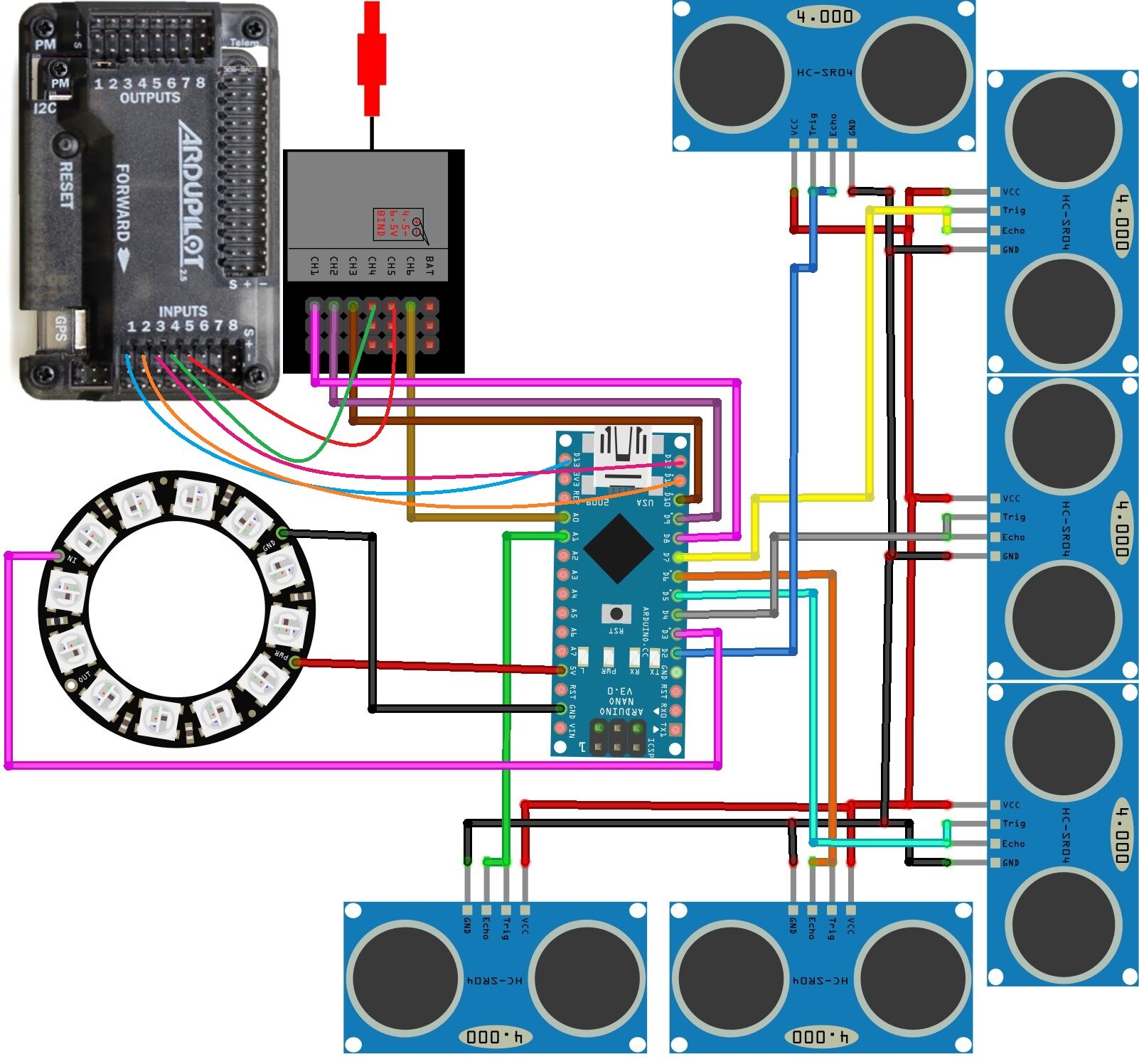
You may also follow the following pin mapping
Ultrasonic sensor->Arduino nano
1. Down Sensor
- VCC -> VIN
- GND -> GND
- TRIG & ECHO -> A1
2. Up Sensor
- VCC -> VIN
- GND -> GND
- TRIG & ECHO -> D6
3. Right Sensor
- VCC -> VIN
- GND -> GND
- TRIG & ECHO -> D5
4. Left Sensor
- VCC -> VIN
- GND -> GND
- TRIG & ECHO -> D4
5. Back Sensor
- VCC -> VIN
- GND -> GND
- TRIG & ECHO -> D7
6. Front Sensor
- VCC -> VIN
- GND -> GND
- TRIG & ECHO -> D2
PWM Receiver->Arduino nano
- Ch1 -> D8
- Ch2 -> D9
- Ch3 -> D10
- Ch4 ->
- Ch5 ->
- Ch6 -> A0
Flight Controller->Arduino nano
- Ch1 -> D13
- Ch2 -> D11
- Ch3 -> D12
- Ch4 ->
- Ch5 ->
- Ch6 -> Not connected
Flight Controller-> PWM Receiver
- Ch4 -> Ch4
- Ch5 -> Ch5
RGB Neopixel->Arduino nano
- GND -> GND
- VCC -> 5V
- OUT -> D3
Make the Circuit
First, download the schematic diagram. The most important thing is any mistakes in the connection may damage the Arduino board. Connect the Sensors, Arduino, Flight controller and RC receiver. Check and double-check the connections.
Proceed to the next stage where we will be uploading the sketch to the Arduino.
Download the Code and Libraries
You can download the Arduino code and supporting libraries from the following links.
Arduino Code:
|
1 2 3 4 5 6 7 8 9 10 11 12 13 14 15 16 17 18 19 20 21 22 23 24 25 26 27 28 29 30 31 32 33 34 35 36 37 38 39 40 41 42 43 44 45 46 47 48 49 50 51 52 53 54 55 56 57 58 59 60 61 62 63 64 65 66 67 68 69 70 71 72 73 74 75 76 77 78 79 80 81 82 83 84 85 86 87 88 89 90 91 92 93 94 95 96 97 98 99 100 101 102 103 104 105 106 107 108 109 110 111 112 113 114 115 116 117 118 119 120 121 122 123 124 125 126 127 128 129 130 131 132 133 134 135 136 137 138 139 140 141 142 143 144 145 146 147 148 149 150 151 152 153 154 155 156 157 158 159 160 161 162 163 164 165 166 167 168 169 170 171 172 173 174 175 176 177 178 179 180 181 182 183 184 185 186 187 188 189 190 191 192 193 194 195 196 197 198 199 200 201 202 203 204 205 206 207 208 209 210 211 212 213 214 215 216 217 218 219 220 221 222 223 224 225 226 227 228 229 230 231 232 233 234 235 236 237 238 239 240 241 242 243 244 245 246 247 248 249 250 251 252 253 254 255 256 257 258 259 260 261 262 263 264 265 266 267 268 269 270 271 272 273 274 275 276 277 278 279 280 |
#include<NewPing.h> //Download this library by going to <Tools> & then <Manage Libraries> #include<Servo.h> //Download this library by going to <Tools> & then <Manage Libraries> #include <FastLED.h> //Download this library from github>/ CRGB leds[1]; Servo out1; //roll Servo out2; //pitch Servo out3; //throttle int trig1 = 2; int echo1 = 2; //int trig2 = A1; //int echo2 = A1; int trig3 = 4; int echo3 = 4; int trig4 = 5; int echo4 = 5; int trig5 = 6; int echo5 = 6; int trig6 = 7; int echo6 = 7; int MAX_DISTANCE = 400; NewPing sonar1(trig1,echo1,MAX_DISTANCE); //NewPing sonar2(trig2,echo2,MAX_DISTANCE); NewPing sonar3(trig3,echo3,MAX_DISTANCE); NewPing sonar4(trig4,echo4,MAX_DISTANCE); NewPing sonar5(trig5,echo5,MAX_DISTANCE); NewPing sonar6(trig6,echo6,MAX_DISTANCE); float dist1,dist2,dist3,dist4,dist5,dist6; unsigned long counter_1, counter_2, counter_3, current_count; byte last_CH1_state, last_CH2_state, last_CH3_state; int input_PITCH; //input on D9 of arduino int input_ROLL; //input on D8 of arduino int input_THROTTLE; //input on D10 of arduino int DN; int UP; int antiDN; int prev_time = 0; void setup(){ // Serial.begin(115200); FastLED.addLeds<WS2812, 3, GRB>(leds, 1); PCICR |= (1 << PCIE0); PCMSK0 |= (1 << PCINT0); PCMSK0 |= (1 << PCINT1); PCMSK0 |= (1 << PCINT2); out1.attach(13); //roll out2.attach(11); //pitch out3.attach(12); //throttle pinMode(A0,INPUT); } void loop(){ int a=160; int b=160; int c=160; int d=160; int e=160; if(input_ROLL>1600){ d=210; } else if(input_ROLL<1400){ c=210; } if(input_PITCH>1600){ a=210; } else if(input_PITCH<1400){ b=210; } dist1 = sonar1.ping_cm(); dist2 = sonar6.ping_cm(); dist3 = sonar3.ping_cm(); dist4 = sonar4.ping_cm(); dist5 = sonar5.ping_cm(); dist6 = 200; // This Sensor is disabled due to my bad sensor.If you want to enable just replace "200" with "sonar6.ping_cm()" byte roll = map(input_ROLL, 1108, 1856, 55, 125); //maping roll byte pitch = map(input_PITCH, 1180, 1856, 55, 125); //maping pitch byte throttle = map(input_THROTTLE, 1160, 1830, 55, 125); //maping throttle byte antifront = map(dist1, 6, 210, 55, 60); //force to back byte antiback = map(dist2, 6, 210, 125, 120); //force to front byte antileft = map(dist3, 6, 210, 125, 120); //force to right byte antiright = map(dist4, 6, 210, 55, 60); //force to left byte antidown = map(dist6, 1, 100, 125, 120); //force to up byte antiUP = map(dist5, 2, 210, 55, 60); //force to down int val = pulseIn(A0,HIGH); if(val < 1500){ // For Pitch.............. if(dist1<a && dist1>0 && (dist2>b || dist2==0)){ out2.write(antifront); b=210; } else if((dist1>=a || dist1==0) && (dist2>=b || dist2==0)){ out2.write(pitch); } else if(dist2<b && dist2>0 && (dist1>a || dist1==0)){ out2.write(antiback); a=210; } else if(dist1<a && dist2<b && dist1>0 && dist2>0){ out2.write(92); c=210; d=210; e=210; if(dist3>c || dist3==0){ out1.write(55); } else if(dist4>d || dist4==0){ out1.write(125); } else if(dist5>e ||dist5==0){ out3.write(110); } else if(dist6>50 ||dist6==0){ out3.write(60); } } // For Roll.............. if(dist3<c && dist3>0 && (dist4>d || dist4==0)){ out1.write(antileft); d=210; } else if(dist3>=c || dist3==0 && dist4>=d || dist4==0){ out1.write(roll); } else if(dist4<d && dist4>0 && (dist3>c || dist3==0)){ out1.write(antiright); c=210; } else if(dist3<c && dist4<d && dist3>0 && dist4>0){ out1.write(92); a=210; b=210; e=210; if(dist1>a || dist1 ==0){ out2.write(125); } else if(dist2>b || dist2 ==0){ out2.write(55); } else if(dist5>e || dist5 ==0){ out3.write(110); } else if(dist6>50 || dist6 ==0){ out3.write(60); } } // For Throttle.............. if(dist5<e && dist5>0 && (dist6>50 || dist6==0)){ out3.write(antiUP); } else if(dist5>=e || dist5==0 && dist6>=50 || dist6==0){ out3.write(throttle); } else if(dist6<50 && dist6>0 && (dist5>e || dist5==0)){ out3.write(antidown); } else if(dist5<e && dist6<50 && dist5>0 && dist6>0){ out3.write(88); a=210; b=210; c=210; d=210; if(dist1>a || dist1==0){ out2.write(125); } else if(dist2>b || dist2==0){ out2.write(55); } else if(dist3>c|| dist3==0){ out1.write(125); } else if(dist4>d || dist4==0){ out1.write(55); } } if(input_THROTTLE <= 1400){ out3.write(throttle); } int FB = (dist1<a && dist2<b && dist1>0 && dist2>0); int LR = (dist3<c && dist4<d && dist3>0 && dist4>0); if(FB && LR){ out1.write(92); out2.write(92); if(input_THROTTLE <= 1400){ out3.write(throttle); } else if(dist5>e || dist5==0){ out3.write(110); } else if(dist6>50){ out3.write(60); } else{out3.write(88);} } } else if(val >= 1500){ out1.write(roll); out2.write(pitch); out3.write(throttle); } int f_clear = (dist1>a || dist1==0); //front no obstacle int b_clear = (dist2>b || dist2==0); //back no obstacle int l_clear = (dist3>c || dist3==0); //left no obstacle int r_clear = (dist4>d || dist4==0); //right no obstacle int up_clear = (dist5>e || dist5==0); //up no obstacle int down_clear = (dist6>50 || dist6==0); //down no obstacle if(f_clear && b_clear && l_clear && r_clear && up_clear && down_clear){ if(val<1500){ leds[0] = CRGB(0, 255, 0); FastLED.show(); out1.write(roll); out2.write(pitch); out3.write(throttle); } else if(val>=1500){ leds[0] = CRGB(235, 255, 200); FastLED.show(); } } else if(dist1<a && dist1>0 || dist2<b && dist2>0 || dist3<c && dist3>0 || dist4<d && dist4>0 || dist5<e &&& dist5>0 || dist6<50 && dist6>0){ if(val<1500){ leds[0] = CRGB(255, 0, 0); FastLED.show(); } else if(val>=1500){ leds[0] = CRGB(235, 255, 200); FastLED.show(); } } } //Here the main loop ends // The Below Codes Reads the PWM value of Receiver ISR(PCINT0_vect){ current_count = micros(); if(PINB & B00000001){ if(last_CH1_state == 0){ last_CH1_state = 1; counter_1 = current_count; } } else if(last_CH1_state == 1){ last_CH1_state = 0; input_ROLL = current_count - counter_1; } if(PINB & B00000010 ){ if(last_CH2_state == 0){ last_CH2_state = 1; counter_2 = current_count; } } else if(last_CH2_state == 1){ last_CH2_state = 0; input_PITCH = current_count - counter_2; } if(PINB & B00000100 ){ if(last_CH3_state == 0){ last_CH3_state = 1; counter_3 = current_count; } } else if(last_CH3_state == 1){ last_CH3_state = 0; input_THROTTLE = current_count - counter_3; } } |
Libraries:
You can also download these libraries /Download this library by going to <Tools> & then <Manage Libraries>
Upload the Software
After installing all the libraries we can move to upload the code into the Arduino board. First, you have to Copy the code and then paste it onto Arduino IDE.
Now you are ready to upload the code, just hit the upload arrow button.
Testing
If you successfully uploaded the code to the Arduino board.
After this final check, you are ready to Fly.
Hope you find this useful. if yes, like it, share it, and comment with your doubt. For more such projects, follow me! Support my channel on YouTube.
Thank you!
SUBSCRIBE to My YOUTUBE Channel
Follow us on Facebook || and Instagram

