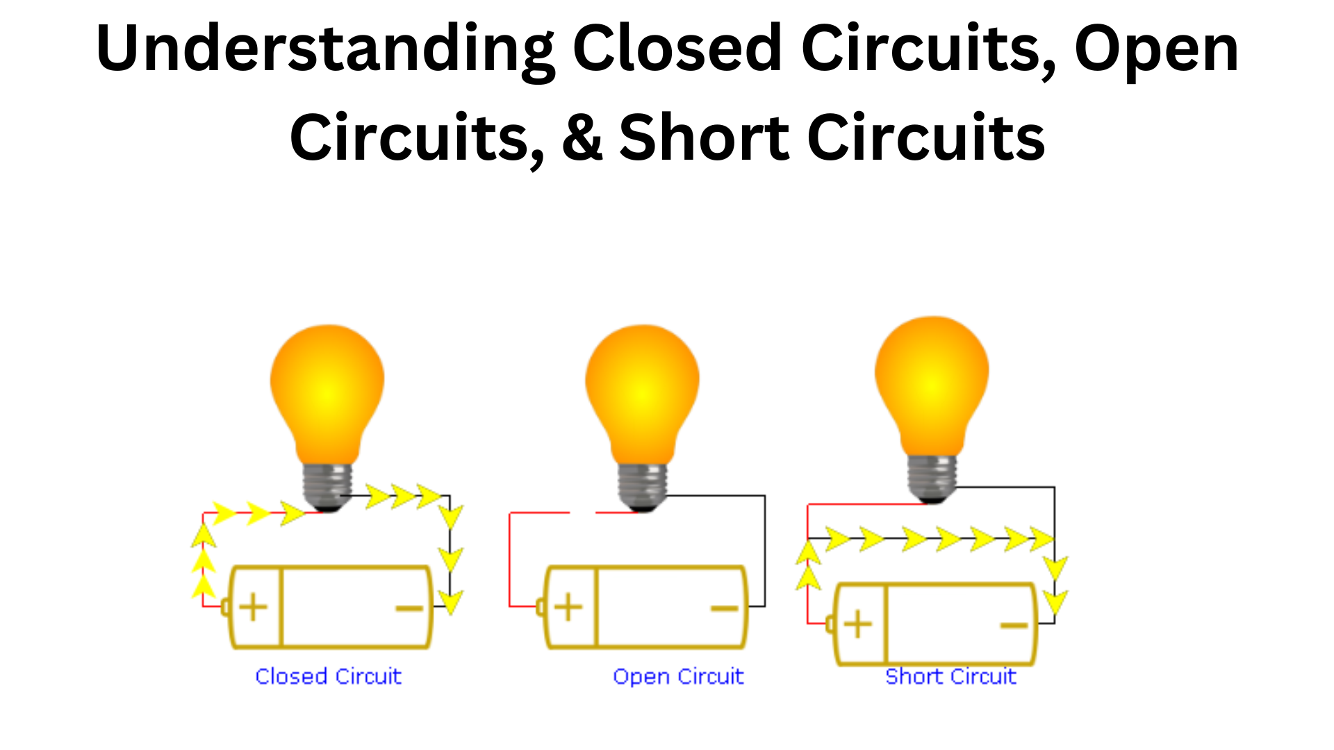
Understanding closed circuits, open circuits, and short circuits is key to understanding how devices work and why they sometimes fail. In this post, I’ll explain these circuits, and explore how they work. Whether you’re a beginner or just curious, let’s get started!
Circuit Diagram
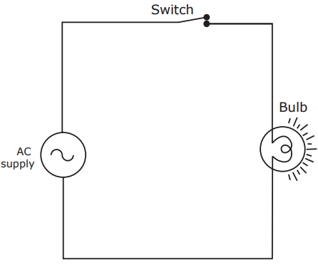
An electrical technician can easily draw electrical connections if simplified symbols are used. Below is a sample electrical circuit diagram.
A method of drawing electrical connections with simplified symbols is called
circuit diagram.
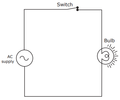
Closed Circuit
A circuit is connected so that it allows current to flow through one or more loads concerning the electrical supply. In a closed circuit, current will flow as shown in the image below.
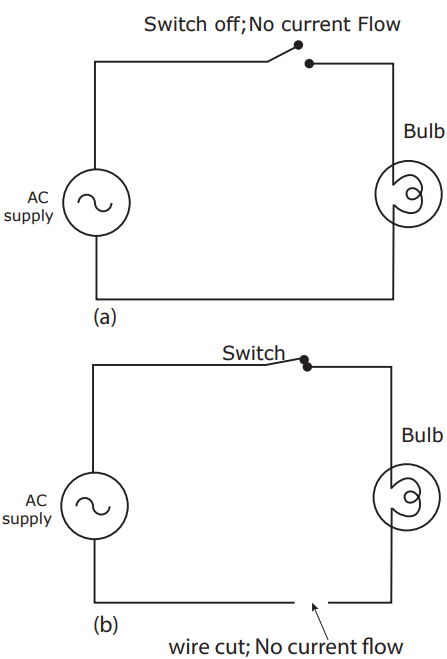
Open Circuit
If no current flows in a circuit due to the disconnection of a wire or a switched-off condition, it is said to be an open circuit. The image below shows a sample of an open circuit.
Short Circuit
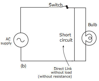
If the two terminals of a power supply are connected directly without any load in a circuit, the circuit is said to be in a short circuit condition.
Example:
As you can see above image shows a circuit in a short circuit condition where an AC supply is directly linked without any load (without resistance).
In this circuit, the flow of current is infinite (I=∞I = \infty A). When a short circuit occurs, a huge amount of heat is produced, and a heavy spark can result. This can cause electrical fires, making it very dangerous.
To prevent such accidents, devices like fuse wires, main circuit breakers (MCB), and Earth leakage circuit breakers (ELCB) are used in electrical circuits.

