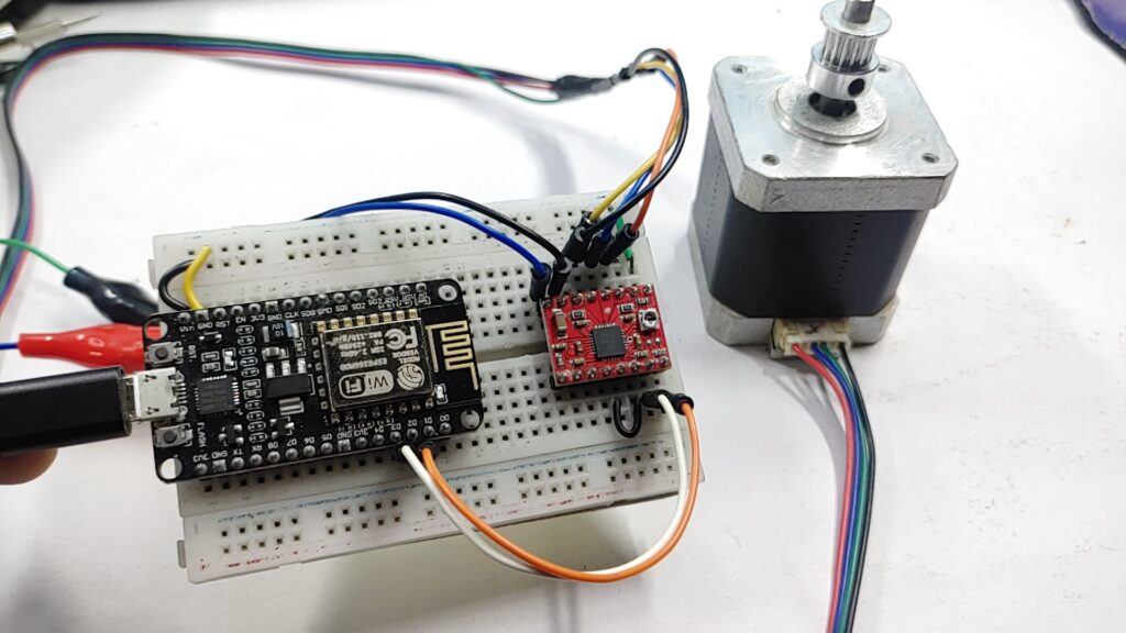
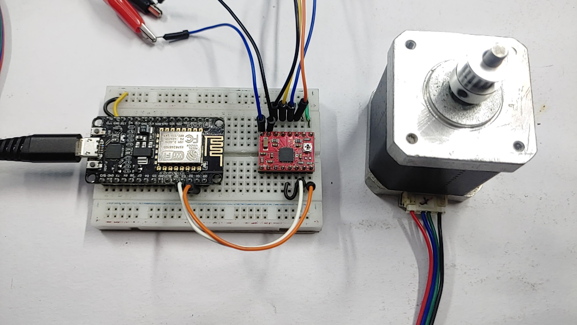
In this tutorial, we will show how to control stepper motors with ESP8266 and A4988 stepper motor drivers. A4988 motor driver is a popular and low-cost motor driver that is used to control stepper motors. ESP8266 and A4988 driver allows you to control the stepper motor’s movement.
ESP8266 and stepper motors can be used to build projects, like CNC machines, 3D printers, automated stairs, and much more.
Checkout our previous post on
- Control 28BYJ-48 Stepper Motor With Raspberry Pi Pico – Micropython
- Control A Stepper Motor With Arduino & A4988 Driver
- 28BYJ-48 Stepper Motor With Arduino Using ULN2003 Driver
Required Material
- ESP8266 board
- A4988 stepper motor driver
- Stepper motor
- Power supply
- Jumper wires
- Breadboard
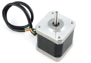
NEMA17 Stepper Motor
A stepper motor is a type of electrical motor that moves in specific steps when it receives an electrical pulse signal. Unlike other types of electric motors, which rotate continuously, stepper motors move in thorough, fixed steps. This makes them perfect for projects that require exact positioning and control, as the motor can be programmed to move very accurately.
Stepper motors are generally used in different applications, like robotics, automation, CNC machines, 3D printers, and many others.
They are especially helpful in conditions when the exact control of motion is required, such as in the movement of robotic arms or the positioning of a camera lens.
Pinout Of NEMA17 Stepper Motor
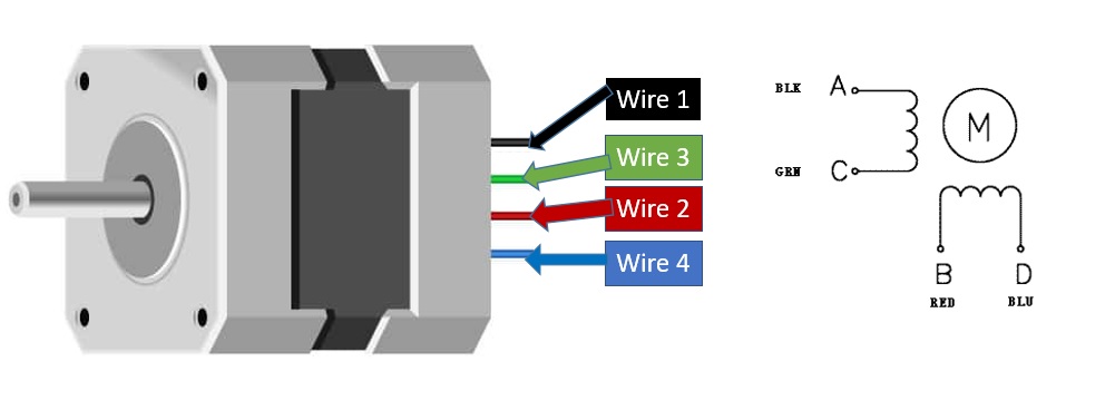
The NEMA17 stepper motor has four wires that are used to control the motor’s two coils.
- A+ (Black wire) – is connected to one end of the first coil.
- A- (Green wire) – is connected to the other end of the first coil.
- B+ (Red wire) – is connected to one end of the second coil.
- B- (Blue wire) – is connected to the other end of the second coil.
Specification NEMA17 Stepper Motor
Here are the specifications of the NEMA17 stepper motor
- Step Angle: 1.8°
- Rated Voltage: 12V or 24V DC
- Rated Current/phase: 1.5A
- Holding Torque: 40Ncm (57.1 oz. in)
- Number of Leads: 4
- Shaft Diameter: 5mm
- Shaft Length: 22mm
- Motor Length: 40mm
- Weight: 280g
- Insulation Resistance: 100MΩ Min.
Application Of NEMA17 Stepper Motor
- 3D Printing
- CNC Machines
- Robotics
- Industrial Automation
- Medical Devices
- Camera Control Systems
- Electric Valve Control
- Automated Test Equipment
- Packaging Equipment
- Automated Guided Vehicles (AGVs)
A4988 Stepper Motor Driver
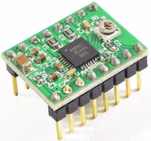
The A4988 is a stepper motor driver that can be used to control the movement of a stepper motor. It is a type of pulse width modulation (PWM) driver that can provide up to 2A of current to the motor, making it well-suited for multiple applications. It is a popular driver among makers and DIY enthusiasts due to its low cost, high performance, and ease of use.
The driver requires a digital signal to control the operation of the motive power. The signal can be provided by a microcontroller such as the ESP8266. Using a microcontroller, the user can adjust the frequency, duration, and strength of the signal to control the operating parameters such as speed and rotation direction.
The A4988 driver also includes built-in protection features such as over-temperature shutdown, under-voltage lockout, and cross-current protection, which help to protect the motor and driver from breakage.
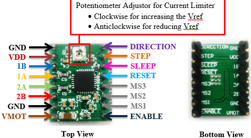
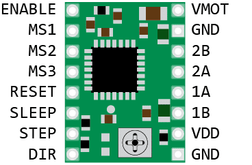
Pinout of A4988 Stepper Motor Driver
The pinout of an A4988 stepper motor driver consists of eight pins, which are numbered and labeled as follows:
The A4988 driver pins are:
- Power Supply Pins: VDD & VMOT & Pair of GND pins
- Microstep Selection Pins: MS1, MS2 & MS3
- Control Input Pins: STEP & DIR
- Power States Control Pin: EN, RST, and SLP
- Output Pins: 2B, 2A, 1B, 1A
Specification of A4988 Stepper Motor Driver
- Operating Voltage: 8-35V
- Maximum current per phase: 2A (with proper heatsinking)
- Microstep resolution: Full step, ½ step, ¼ step, 1/8 and 1/16 step
- Thermal Shutdown Circuitry: Yes
- Short-to-Ground and Shorted-Load Protection: Yes
- Low RDS(ON) Outputs: Yes
- Step and Direction Control: Yes
- Enable Input for Disable/Enable Motor: Yes
- Power-On Reset Function: Yes
- Cross Current Protection: Yes
- Dimensions: 15.5mm x 20.5mm (0.6″ x 0.8″)
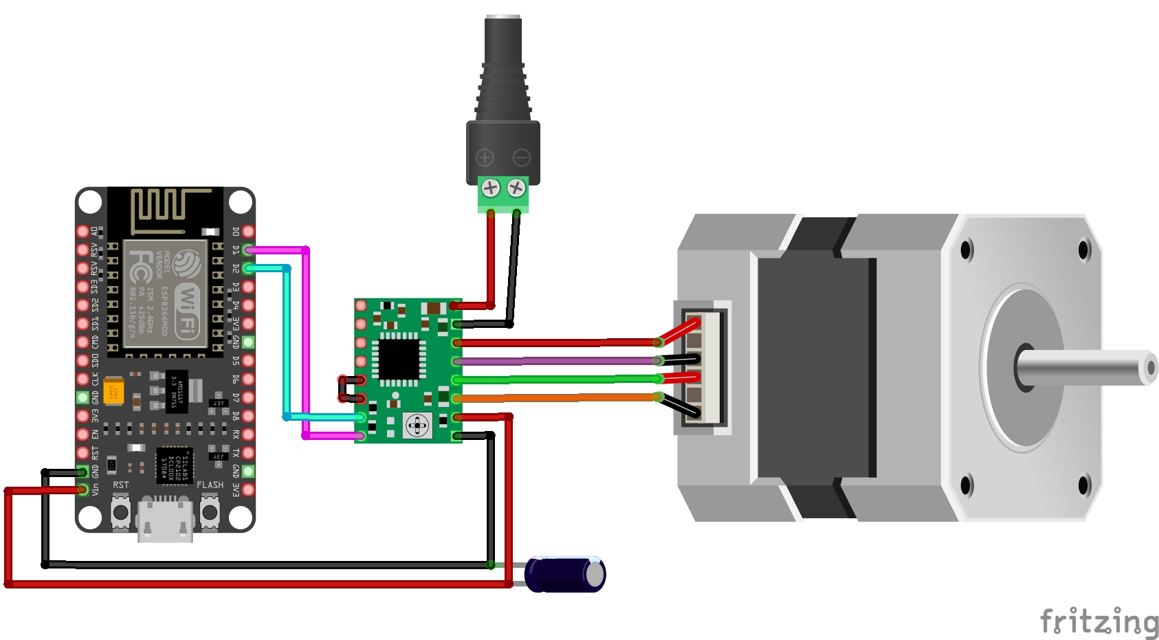
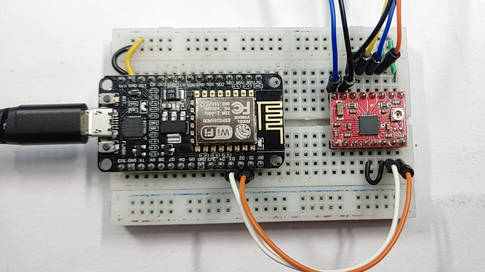
Wiring Diagram – Stepper Motor With ESP8266 & A4988 Motor Driver
A schematic diagram of an ESP8266 and A4988 controlling a stepper motor is shown in the first diagram.
- ESP8266 D5 pin to A4988 STEP pin
- ESP8266 D6 pin to A4988 DIR pin
Connect the stepper motor to the A4988 driver. Make sure you connect the following wires from the stepper motor to their corresponding pins on the A4988 driver:
- Stepper motor A+ to A4988 A1 pin
- Stepper motor A- to A4988 A2 pin
- Stepper motor B+ to A4988 B1 pin
- Stepper motor B- to A4988 B2 pin
Connect a 12V power supply to the A4988 driver. Plug the positive wire from the power supply into the A4988 VMOT pin and the negative wire into the A4988 GND pin.
Add a 0.1uF capacitor between the A4988 VDD pin and GND pin to provide filtering and decoupling for the driver.
Source Code
Once the circuit is complete, Copy the below code and upload it through Arduino IDE In ESP8266 Bord.
|
1 2 3 4 5 6 7 8 9 10 11 12 13 14 15 16 17 18 19 20 21 22 23 24 25 26 27 28 29 30 31 32 33 34 35 36 37 38 39 40 41 42 43 |
const int dirPin = 5; const int stepPin = 4; const int stepsPerRevolution = 200; const int delayTime = 1000; // in microseconds, adjust this to change speed void setup() { // Declare pins as Outputs pinMode(stepPin, OUTPUT); pinMode(dirPin, OUTPUT); } void loop() { clockwiseRotation(); delay(1000); counterclockwiseRotation(); delay(1000); } void clockwiseRotation() { // Set motor direction clockwise digitalWrite(dirPin, HIGH); // Spin motor at a constant speed for(int x = 0; x < stepsPerRevolution; x++) { digitalWrite(stepPin, HIGH); delayMicroseconds(delayTime); digitalWrite(stepPin, LOW); delayMicroseconds(delayTime); } } void counterclockwiseRotation() { // Set motor direction counterclockwise digitalWrite(dirPin, LOW); // Spin motor at a constant speed for(int x = 0; x < stepsPerRevolution; x++) { digitalWrite(stepPin, HIGH); delayMicroseconds(delayTime); digitalWrite(stepPin, LOW); delayMicroseconds(delayTime); } } |

