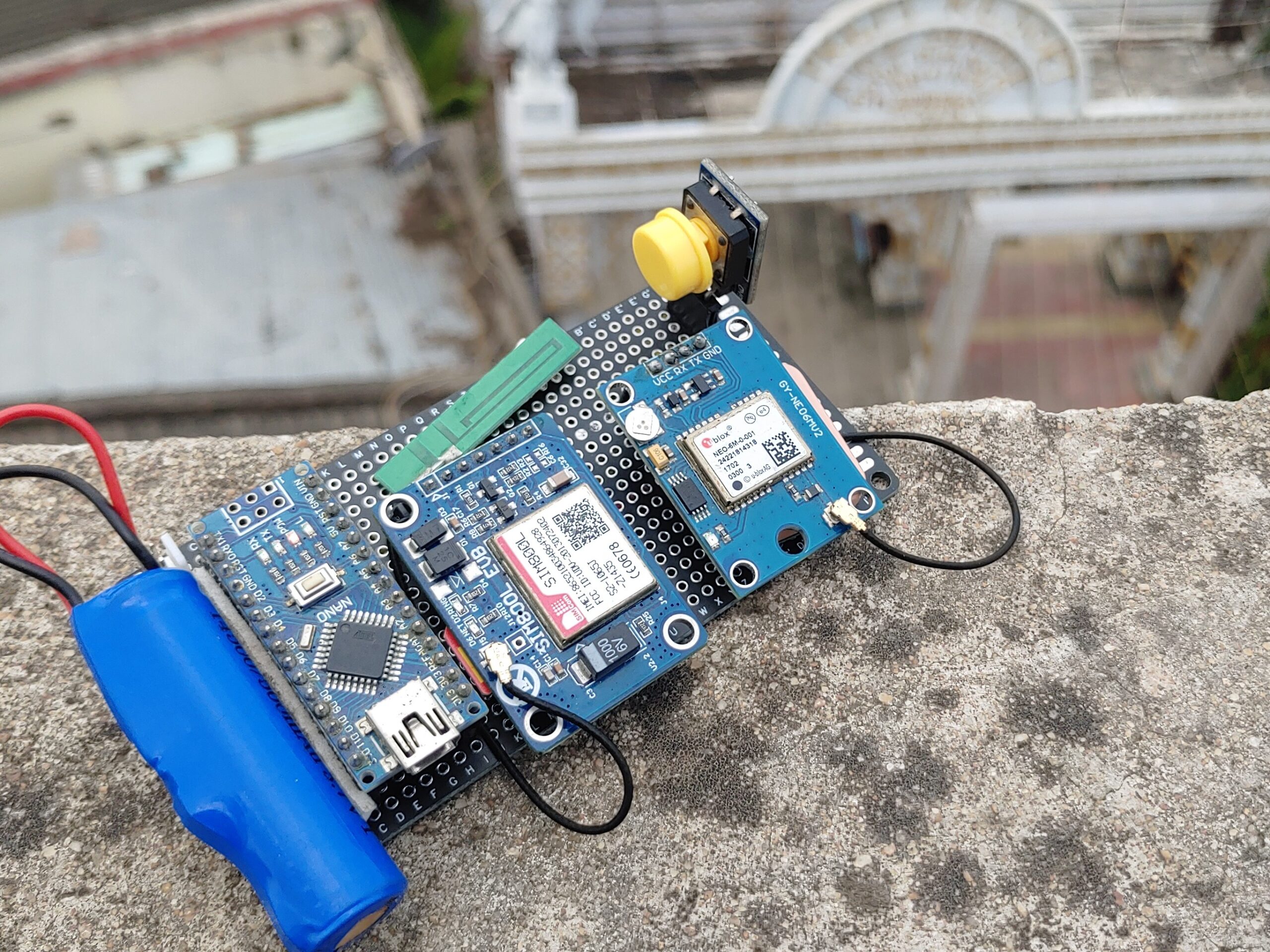
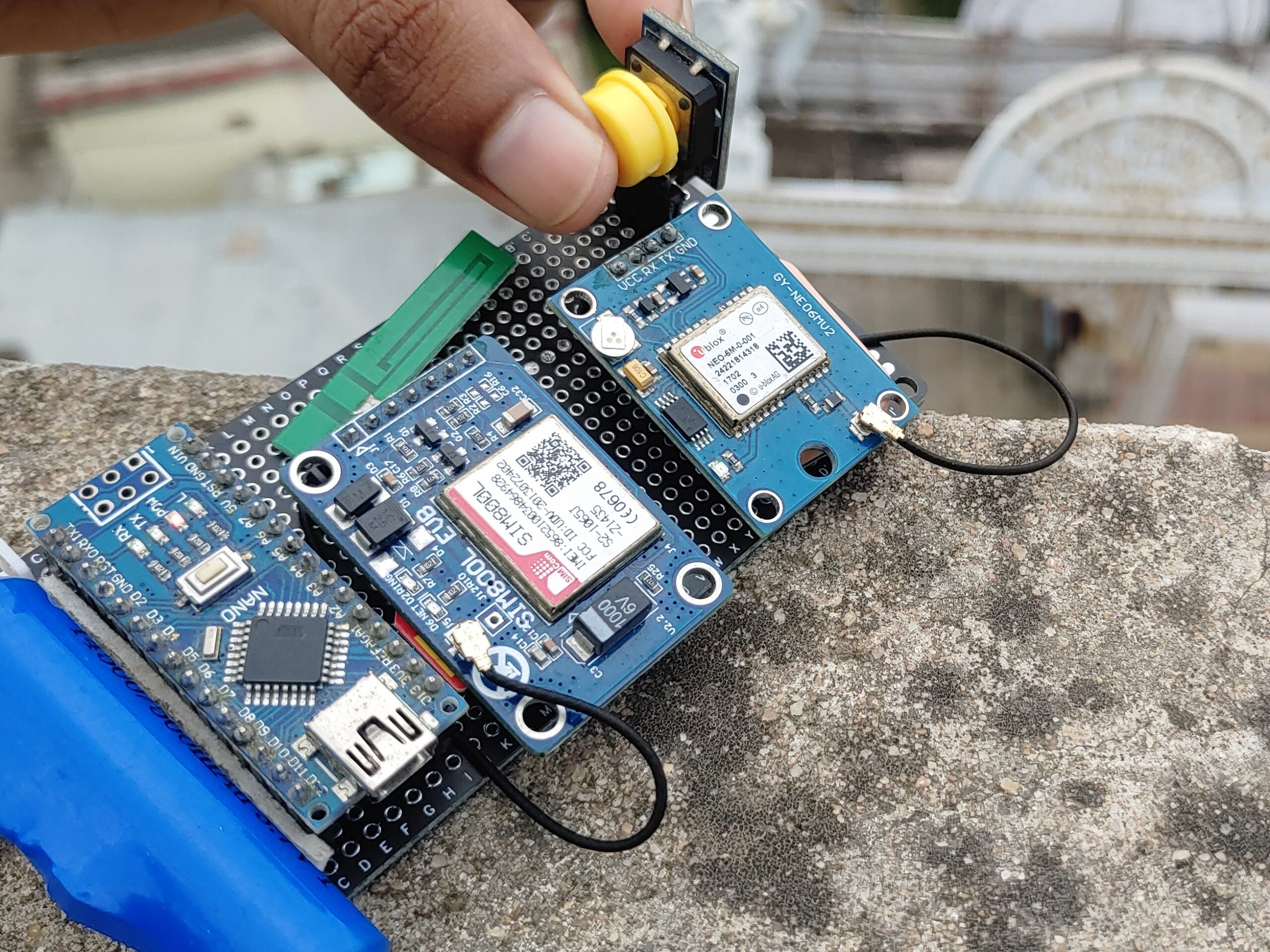
This is a small Arduino GPS tracker built with Arduino Nano, designed to be attached to a car, bicycle, motorcycle, or any vehicle. It tracks the vehicle’s location and sends an SMS with the coordinates, which can be viewed on a map via a web link. The tracker updates the vehicle’s coordinates and sends an alert when needed.
This project is especially useful for emergency situations where you need to fast share your location with somebody else.
Thank You, PCBWay!
This project was made possible with the support of PCBWay. If you’re going to build PCB projects, check out their website for great deals and discounts.
PCBWay is the go-to for quality prototype PCBs at affordable prices. Sign up through this link to get a free coupon or rewards on your first order: PCBWay
Required Materials
- Arduino Nano/Uno/Micro
- GPS Neo 6M Module
- SIM800L Module
- SIM Card
- Push Button
- Breadboard or Zero Pcbs
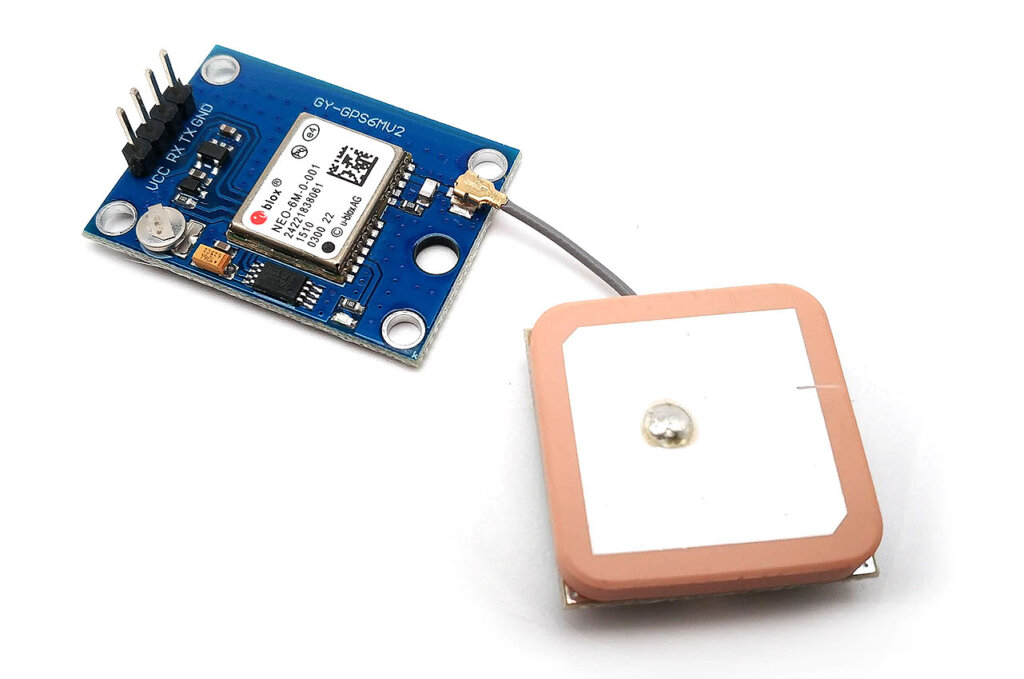
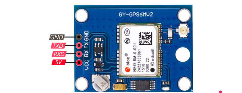
Neo 6M GPS Module
The Global Positioning System (GPS) uses 31 satellites orbiting Earth to transmit location and time data through radio signals. The NEO-6M GPS module, developed by u-blox, is the core of the breakout board. It’s a small but powerful module, capable of tracking up to 22 satellites over 50 channels while using only 45mA of current. A key feature is its power-saving mode, which reduces current consumption to just 11mA.
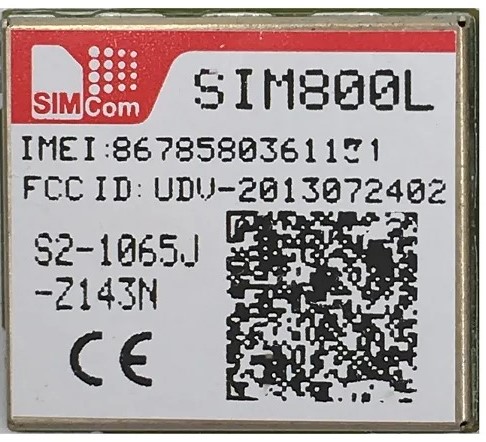
SIM800L Module
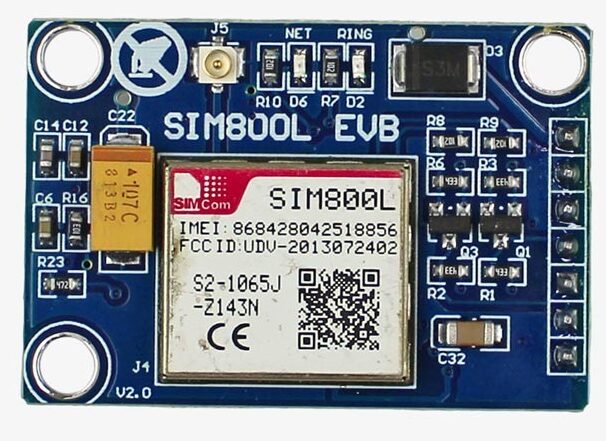
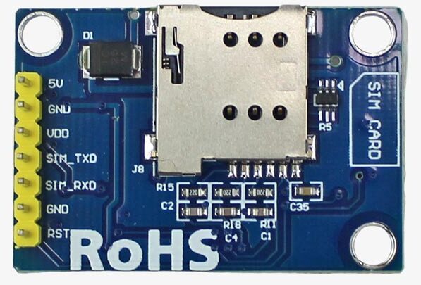
SIM800L GSM/GPRS Module, designed by SimCom. This module operates at a voltage of 3.4V to 4.4V, making it ideal for powering directly with a lithium polymer battery.
It also features auto baud rate detection, simplifying setup. SIM800L requires an external antenna to connect to the network, and the board offers two antenna options: Check out a previous post on GSM – Sending and Receiving Calls & SMS with SIM800 GSM Module
The SIM800L V2.0 GSM/GPRS Module is a 5V wireless module compatible with Arduino and other microcontrollers. It supports both GSM and GPRS features and can be directly connected to 5V. The module uses a built-in regulator and TTL level converter, making it easy to use.
It comes with an IPX antenna interface that allows switching between a PCB antenna and a suction cup antenna. The module supports quad-band communication, making it ideal for global use in projects.
SIM800L Module Pinout
- 5V: Power Interface – Connect to DC 5V to power the module.
- GND: Ground – Connect to the ground (GND).
- VDD: TTL UART Interface – Used for connecting to MCUs (e.g., 51MCU, ARM, MSP430). This pin matches the voltage of the TTL interface.
- SIM_TXD: Transmitter – The SIM module’s transmit pin.
- SIM_RXD: Receiver – The SIM module’s receive pin.
- GND: Ground – If unused, leave this pin open.
- RST: Reset – Resets the module. If unused, leave this pin open
|
1 |
Note - The module is compatible with any 2G-3G SIM card. |
LED Status Indicator:
The SIM800L module has an LED indicator that shows the network status by blinking at different times:
- Blinking every 1 second: The module is powered on but not yet connected to the cellular network.
- Blinking every 2 seconds: The GPRS data connection is active and ready for data transfer.
- Blinking every 3 seconds: The module is connected to a network and ready to send/receive voice calls and SMS messages.
How It Works – Arduino GPS Tracker
The GPS module continuously receives coordinates from satellites, determining your location. The GSM module then uses this data to send an SMS with your GPS location to an added phone number when a button is pressed.
The device can also call if the button is held down for over five seconds. LoRa GPS-Based IoT Geo-Fencing Using Arduino, and ESP32
The GPS Neo 6M module receives coordinates (latitude and longitude) from satellites orbiting the Earth. To work properly, the GPS receiver must connect to signals from at least three satellites. With four or more satellites, it can determine your 3D position(latitude, longitude, and altitude). Usually, it tracks eight or more satellites, but this can vary depending on the time of day and your location. Check Out the Last post Live Vehicle GPS Tracking with Telegram and ESP32 on Google Maps
Wiring Diagram – DIY Arduino GPS Tracker Project
The circuit Diagram for the Arduino GPS Tracker is given below.
Here we are interfacing the Arduino with the GPS Module and GSM Module. The connection is fairly simple. Connect the VCC/GND for the power supply.
- GSM Module
- Arduino Pin 3 (TX) to GSM Module RX
- Arduino Pin 2 (RX) to GSM Module TX
- GPS Module
- Arduino Serial RX to GPS Module TX
- Button
- Arduino Pin 12 (Input) to one side of the button
Source Code/Program
Make sure you have the TinyGPS.h library installed.
- Update the Mobile Number:
- Before uploading the code, change the
phone_noto your phone number.
- Before uploading the code, change the
|
1 |
char phone_no[] = "+91xxxxxxxxxx"; // Replace with your phone number |
Once you’ve updated the phone number then upload it to the Arduino Board.
|
1 2 3 4 5 6 7 8 9 10 11 12 13 14 15 16 17 18 19 20 21 22 23 24 25 26 27 28 29 30 31 32 33 34 35 36 37 38 39 40 41 42 43 44 45 46 47 48 49 50 51 52 53 54 55 56 57 58 59 60 61 62 63 64 65 66 67 68 69 70 71 72 73 74 75 76 77 78 79 80 81 82 83 84 85 86 87 88 89 90 91 92 |
#include <TinyGPS.h> #include <SoftwareSerial.h> #include <Wire.h> SoftwareSerial Gsm(3, 2); // RX, TX pins for GSM module char phone_no[] = "+91xxxxxxxx"; // Your phone number TinyGPS gps; int buttonState; unsigned long buttonPressTime; bool isSMSsent = false; void setup() { Serial.begin(9600); Gsm.begin(9600); // Set GSM module to text mode Gsm.print("AT+CMGF=1\r"); delay(100); // Configure the GSM module to display incoming SMS Gsm.print("AT+CNMI=2,2,0,0,0\r"); delay(100); pinMode(12, INPUT_PULLUP); // Set pin 12 as input for a button or sensor } void loop() { bool newData = false; unsigned long chars; unsigned short sentences, failed; // Reading GPS data for (unsigned long start = millis(); millis() - start < 1000;) { while (Serial.available()) { char c = Serial.read(); Serial.print(c); // Output GPS data to the Serial Monitor if (gps.encode(c)) newData = true; // Check if there is new GPS data } } buttonState = digitalRead(12); // Read the state of the input pin if (buttonState == LOW) { // Button is pressed if (!isSMSsent) { buttonPressTime = millis(); // Record the time when the button was first pressed // Send SMS with GPS location float flat, flon; unsigned long age; gps.f_get_position(&flat, &flon, &age); Gsm.print("AT+CMGF=1\r"); delay(400); Gsm.print("AT+CMGS=\""); Gsm.print(phone_no); Gsm.println("\""); Gsm.println("Emergency! I’m in danger!..."); Gsm.print("http://maps.google.com/maps?q=loc:"); Gsm.print(flat == TinyGPS::GPS_INVALID_F_ANGLE ? 0.0 : flat, 6); Gsm.print(","); Gsm.print(flon == TinyGPS::GPS_INVALID_F_ANGLE ? 0.0 : flon, 6); delay(200); Gsm.println((char)26); // End of SMS character delay(200); Serial.println("SMS Sent"); isSMSsent = true; // Mark SMS as sent to avoid resending } // Check if the button is held down for more than 5 seconds if (millis() - buttonPressTime > 5000) { Serial.println("Button held for 5 seconds, making a call..."); // Make a phone call Gsm.print("ATD"); Gsm.print(phone_no); Gsm.println(";"); delay(20000); // Wait for the call to go through Gsm.println("ATH"); // Hang up the call delay(1000); Serial.println("Call ended"); isSMSsent = false; // Reset SMS sent flag for future button presses } } else { isSMSsent = false; // Reset SMS sent flag when button is released delay(10); // Wait before the next loop } Serial.println(failed); // Output the number of failed GPS sentences } |
Testing Your GPS Tracker
After uploading the code to your Arduino, open the Serial Monitor. The Serial Monitor will show an initialization message. Once the GPS module has fixed onto a location, the Serial Monitor will display the data coordinates.
When you press the button, the GSM module sends a text message with the correct GPS coordinates after a few seconds.
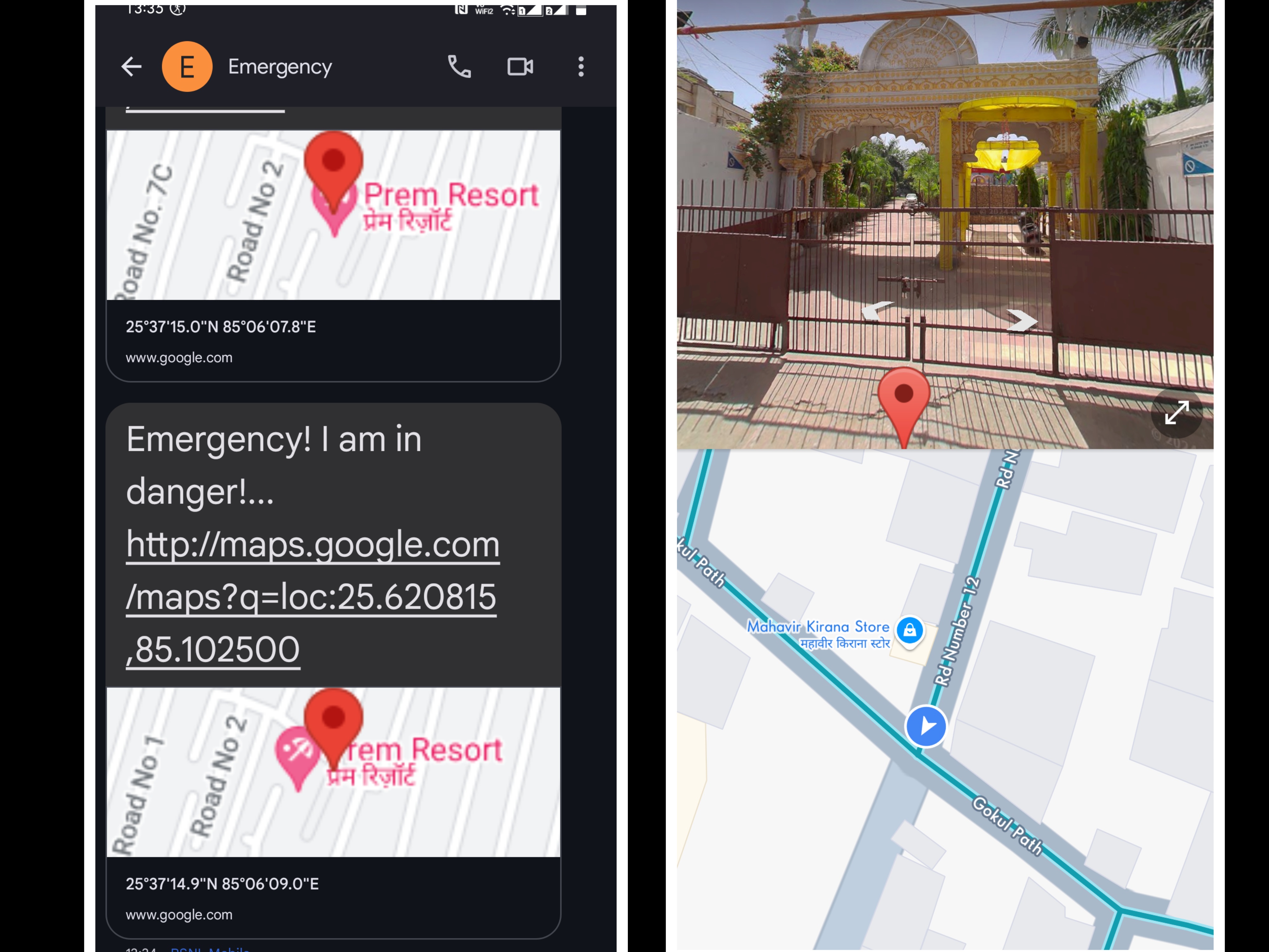
You will receive an SMS on your mobile phone containing a Google Maps link. By clicking the link, you can view the exact location on Google Maps, either via the app or in a web browser like Chrome.
If you hold the button for 5 seconds, the system will call the same number. If you want the call to go to a different number, you’ll need to change the code.


