This post shows how to make a DIY Arduino speedometer using an analog gauge and a GPS module. The gauge is used to display the current speed, while the GPS module is used to track the speed in real-time. this project combines an Arduino board with a GPS module to display real-time speed on a classic analog gauge.
GPS speedometers are more accurate than traditional speedometers because they can continually track the vehicle’s location and calculate its speed. You may already be familiar with GPS, as it’s commonly used in smartphones. checkout my previous post on How To Use NEO-6M GPS Module with Arduino | Tutorial
Thank You, NextPCB
This project was successfully completed because of the support and help from NextPCB. Guys if you have a PCB project, please see their website and get exciting bargains and coupons.
NextPCB offers high-quality, reliable PCB starting at $1.9, and multilayer starting at $6.9. Also, everyone can enjoy free PCB assembly for 5 boards!
Required materials
- 0.96″ OLED display
- GPS module (such as NEO-6M or NEO-7M)
- Jumper wires
- Breadboard
- USB cable
NEO6M GPS Module
We will be using the NEO-6M GPS module. The NEO-6M is a popular GPS receiver featuring a built-in ceramic antenna, it offers excellent satellite search capabilities. With the ability to track up to 22 satellites, it provides accurate location information of your position in the world.
The onboard signal indicator allows us to monitor the module’s network status, It has a small battery for data backup so that the module can save data when the main power is shut down accidentally.
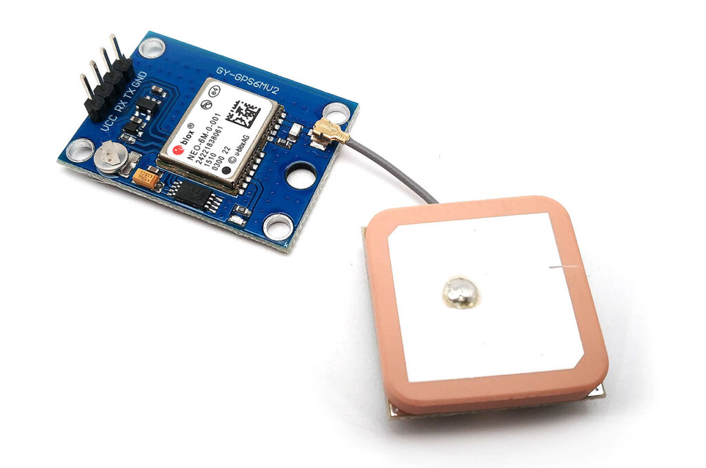
Specifications of NEO6M GPS Module
- GPS Chip: u-blox NEO-6M
- Satellite Tracking: Up to 22 satellites
- Channels: 50 channels for positioning
- Sensitivity: -161 dBm
- Positioning Engine: u-blox 6
- TTFF: Under 1 second
- Baud Rate: Supports 4800-230400 bps (default: 9600 bps)
- Antenna: Built-in ceramic antenna
- Data Backup: Data backup battery
- Compatibility: Arduino, Raspberry Pi, and other microcontrollers
- Operating Voltage: 3.3V-5V
- Power Consumption: Low power consumption
- Communication: Serial communication (UART)
- Output: NMEA protocol
- Applications: Navigation, tracking, robotics, geocaching, and more.
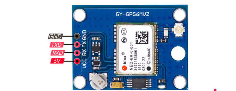
Pinout of NEO6M GPS Module
Pinout for the NEO-6M GPS Module:
- VCC: Input voltage pin
- GND: Ground pin
- RX: Receive pin for UART communication
- TX: Transmit pin for UART communication
NEO-6M GPS Module Tutorials
- NEO-6M GPS Module with Raspberry Pi Pico | Micropython
- Raspberry Pi Pico GPS Tracker Using NEO-6M & OLED Display
- NEO-6M GPS Module with Arduino | Tutorial
Arduino GPS Speedometer Project Circuit Diagram
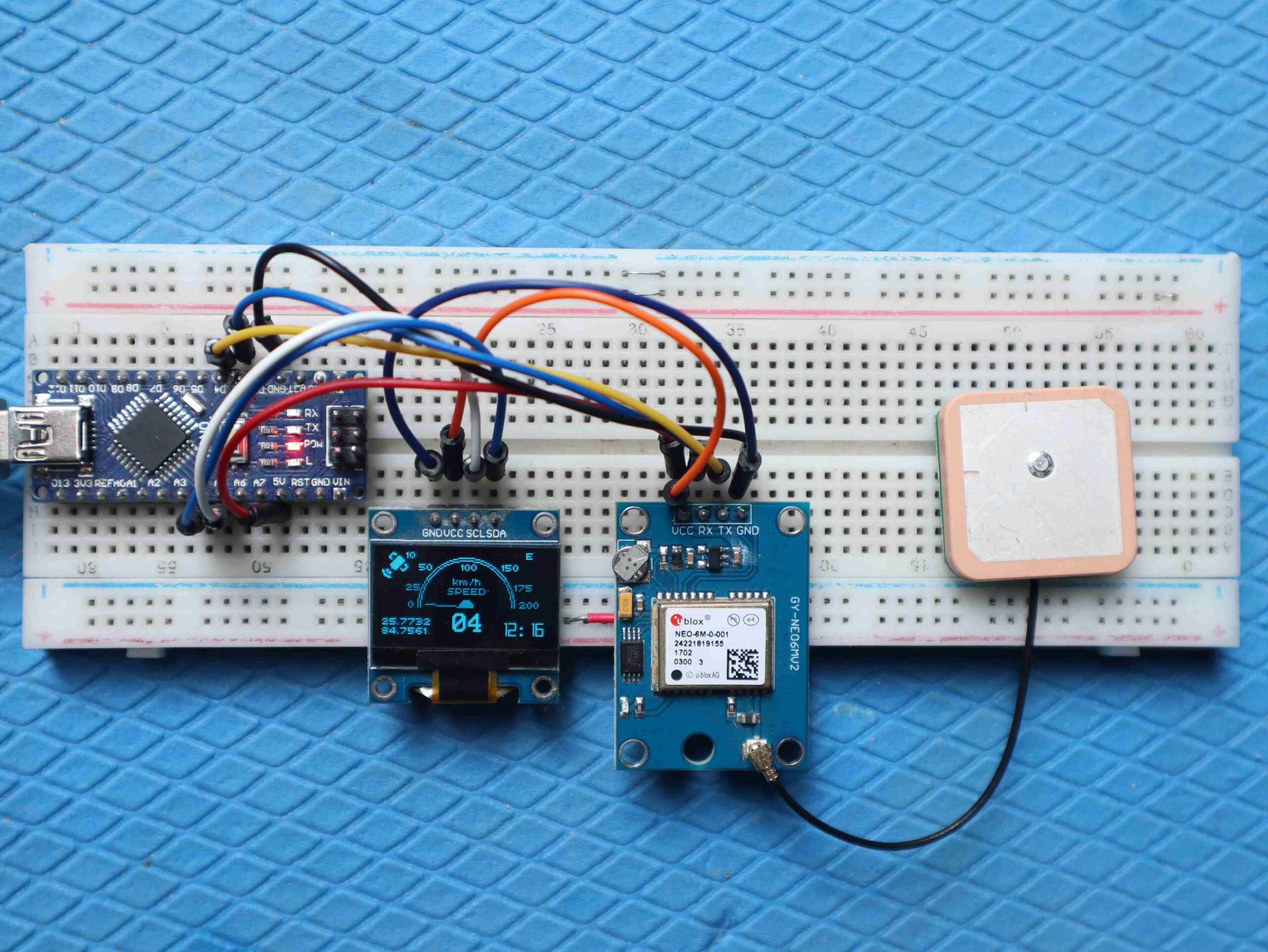
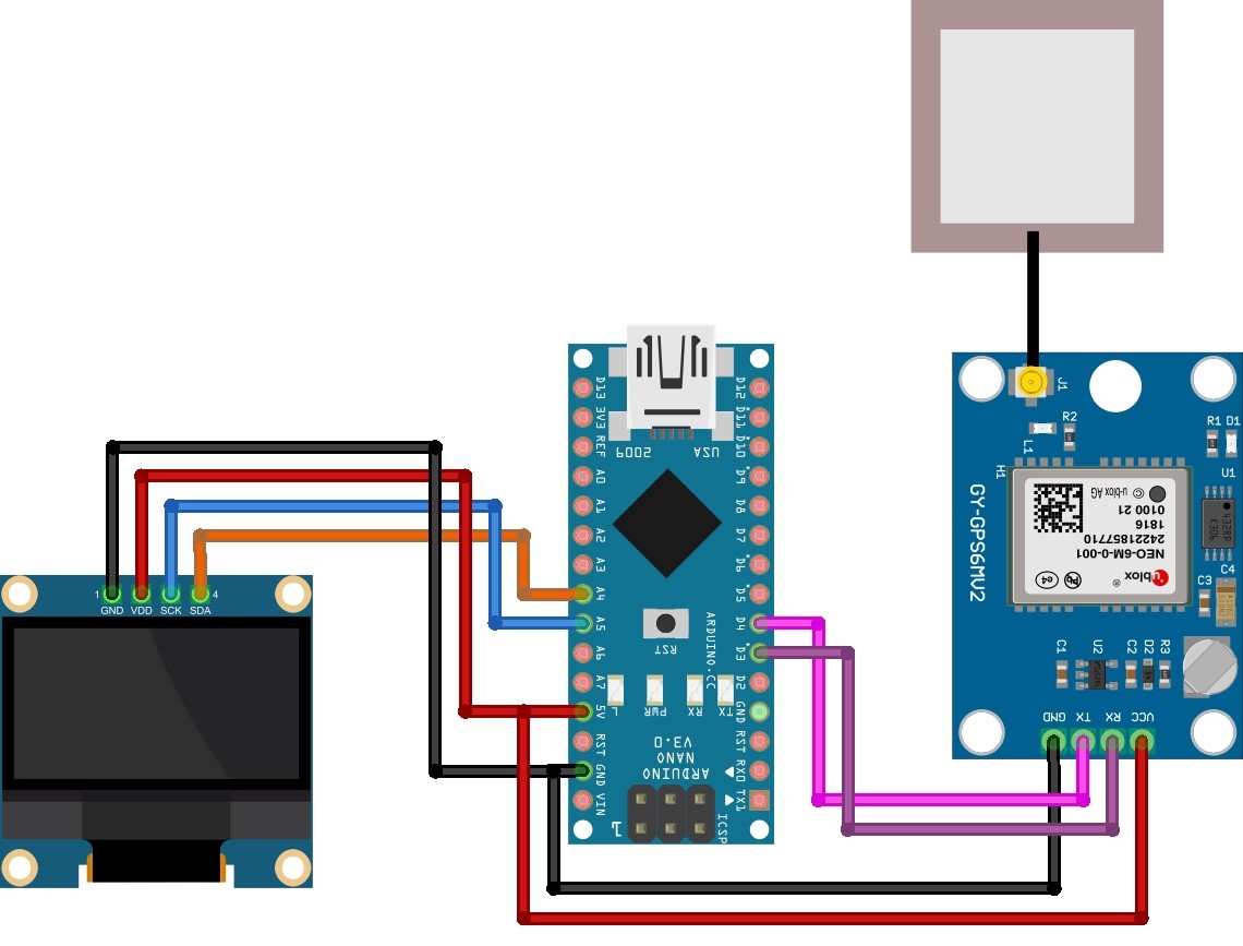
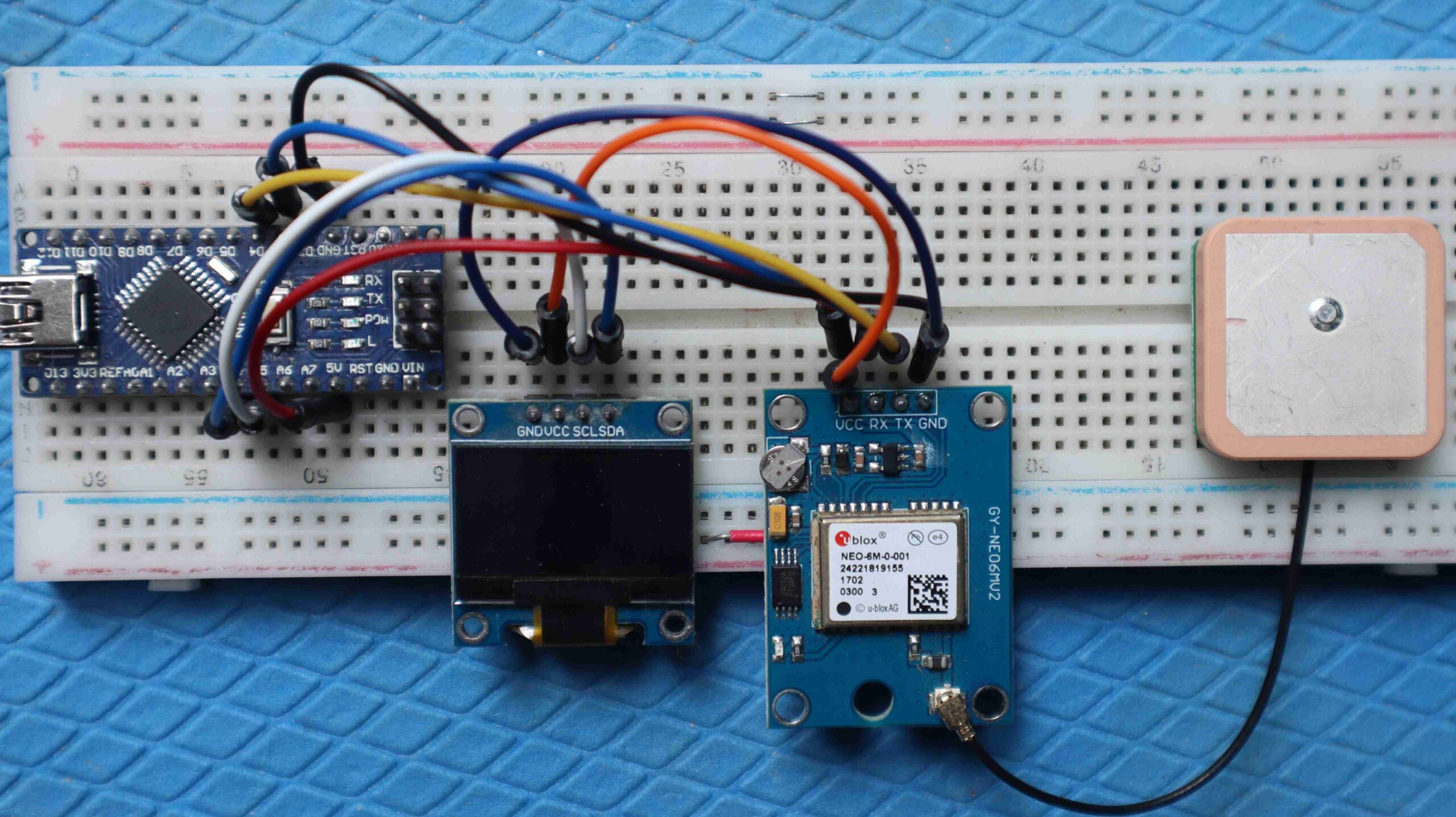
Now let us see the circuit diagram of the Arduino GPS Speedometer. The connection diagram is relatively easy as shown in the image below.
- Connect the VCC pin of the GPS module to the 3.3V pin of the Arduino.
- Connect the GND pin of the GPS module to the GND pin of the Arduino.
- Connect the RX pin of the GPS module to digital pin 3 on the Arduino.
- Connect the TX pin of the GPS module to digital pin 4 on the Arduino.
Connect the VCC and GND pins of the I2C OLED display to the Arduino’s 5V and GND pins, and connect the SDA and SCL pins to the Arduino’s A4 and A5 pins, respectively.
Source code for Arduino OLED Speedometer
Firstly Import the necessary libraries
Copy the below code and upload it to the Arduino Nano Board.
|
1 2 3 4 5 6 7 8 9 10 11 12 13 14 15 16 17 18 19 20 21 22 23 24 25 26 27 28 29 30 31 32 33 34 35 36 37 38 39 40 41 42 43 44 45 46 47 48 49 50 51 52 53 54 55 56 57 58 59 60 61 62 63 64 65 66 67 68 69 70 71 72 73 74 75 76 77 78 79 80 81 82 83 84 85 86 87 88 89 90 91 92 93 94 95 96 97 98 99 100 101 102 103 104 105 106 107 108 109 110 111 112 113 114 115 116 117 118 119 120 121 122 123 124 125 126 127 128 129 130 131 132 133 134 135 136 137 138 139 140 141 142 143 144 145 146 147 148 149 150 151 152 153 154 155 156 157 158 159 160 161 162 163 164 165 166 167 168 169 170 171 172 173 174 175 176 177 178 179 180 181 182 183 184 185 186 187 188 189 190 191 192 193 194 195 196 197 198 199 200 201 202 203 204 205 206 207 208 209 210 211 212 213 214 215 216 217 218 219 220 221 222 223 224 225 226 227 228 229 230 231 232 233 234 235 236 237 238 239 240 241 242 243 244 245 246 247 248 249 250 |
//--------------------------------------------------------------------------- #include "U8glib.h" U8GLIB_SSD1306_128X64 u8g(U8G_I2C_OPT_NONE|U8G_I2C_OPT_DEV_0); //--------------------------------------------------------------------------- const int timezone_hours = 5; const int timezone_minutes = 0; //--------------------------------------------------------------------------- #include <SoftwareSerial.h> #define rxPin 4 #define txPin 3 SoftwareSerial neogps(rxPin,txPin); #include <TinyGPS++.h> //1.0.3 TinyGPSPlus gps; //--------------------------------------------------------------------------- int x_max = 128; //OLED display width, in pixels int y_max = 62; //OLED display width, in pixels int x_center = x_max/2; int y_center = y_max/2+10; int arc = y_max/2; int angle = 0; //--------------------------------------------------------------------------- int needle_pos = 0; u8g_uint_t xx = 0; //--------------------------------------------------------------------------- //satellite logo #define sat_logo_width 20 #define sat_logo_height 20 const unsigned char sat_logo[] = { 0x00, 0x01, 0x00, 0x80, 0x07, 0x00, 0xc0, 0x06, 0x00, 0x60, 0x30, 0x00, 0x60, 0x78, 0x00, 0xc0, 0xfc, 0x00, 0x00, 0xfe, 0x01, 0x00, 0xff, 0x01, 0x80, 0xff, 0x00, 0xc0, 0x7f, 0x06, 0xc0, 0x3f, 0x06, 0x80, 0x1f, 0x0c, 0x80, 0x4f, 0x06, 0x19, 0xc6, 0x03, 0x1b, 0x80, 0x01, 0x73, 0x00, 0x00, 0x66, 0x00, 0x00, 0x0e, 0x00, 0x00, 0x3c, 0x00, 0x00, 0x70, 0x00, 0x00 }; //--------------------------------------------------------------------------- //Program variables double lat; double lng; //int day, month, year; String hours, minutes; int second; int num_sat, speed; String heading; /******************************************************************************************* * gauge function * dispay gauge and other gps data on oled *******************************************************************************************/ void gauge(uint8_t angle) { //fonts: u8g_font_chikita - u8g_font_04b_03br // u8g_font_orgv01 - u8g_font_freedoomr10r u8g.setFont(u8g_font_chikita); //--------------------------------------------------------------------------- // draw border of the gauge u8g.drawCircle(x_center,y_center,arc+6, U8G_DRAW_UPPER_RIGHT); u8g.drawCircle(x_center,y_center,arc+4, U8G_DRAW_UPPER_RIGHT); u8g.drawCircle(x_center,y_center,arc+6, U8G_DRAW_UPPER_LEFT); u8g.drawCircle(x_center,y_center,arc+4, U8G_DRAW_UPPER_LEFT); //--------------------------------------------------------------------------- // show gauge values u8g.drawStr(20, 42, "0"); u8g.drawStr(18, 29, "25"); u8g.drawStr(28, 14, "50"); u8g.drawStr(60, 14, "100"); u8g.drawStr(91, 14, "150"); u8g.drawStr(101, 29, "175"); u8g.drawStr(105, 42, "200"); //--------------------------------------------------------------------------- // show gauge label u8g.setPrintPos(54,25); u8g.print("km/h"); u8g.setPrintPos(50,32); u8g.print("SPEED"); //--------------------------------------------------------------------------- // draw the needle float x1=sin(2*angle*2*3.14/360); float y1=cos(2*angle*2*3.14/360); u8g.drawLine(x_center, y_center, x_center+arc*x1, y_center-arc*y1); u8g.drawDisc(x_center, y_center, 5, U8G_DRAW_UPPER_LEFT); u8g.drawDisc(x_center, y_center, 5, U8G_DRAW_UPPER_RIGHT); //--------------------------------------------------------------------------- //TOP LEFT: draw satellite logo and number of satellites u8g.drawXBM(0, 0, sat_logo_width, sat_logo_height, sat_logo); u8g.setPrintPos(18, 5); u8g.print(num_sat, 5); //--------------------------------------------------------------------------- //TOP RIGHT: Display direction u8g.setPrintPos(110, 5); u8g.print(heading); //--------------------------------------------------------------------------- //Display latitude and longitude u8g.setPrintPos(0, 55); u8g.print(lat, 4); u8g.setPrintPos(0, 62); u8g.print(lng, 4); //--------------------------------------------------------------------------- //Display time u8g.setFont(u8g_font_freedoomr10r); u8g.setPrintPos(90, 65); u8g.print(hours); if(second%2 == 0) {u8g.drawStr(104, 65, ":");} else {u8g.drawStr(104, 65, " ");} u8g.setPrintPos(111, 65); u8g.print(minutes); //u8g.drawStr(90, 65, "00:00"); //--------------------------------------------------------------------------- // Show Speed and align its position u8g.setFont(u8g_font_profont22); u8g.setPrintPos(54,60); if (speed<10){ u8g.print("0"); } if (speed>99) { u8g.setPrintPos(47,60); } u8g.print(speed); //--------------------------------------------------------------------------- } /******************************************************************************************* * gauge function * dispay gauge and other gps data on oled *******************************************************************************************/ int i = 200; void setup(void) { Serial.begin(9600); neogps.begin(9600); u8g.setFont(u8g_font_chikita); u8g.setColorIndex(1); } /******************************************************************************************* * gauge function * dispay gauge and other gps data on oled *******************************************************************************************/ void loop(void){ //---------------------------------------------------------- Read_GPS(); //---------------------------------------------------------- needle_pos = map(speed,0,200,0,90); //SET NEEDLE // show needle and dial xx = needle_pos; if (xx<45) {xx=xx+135;} else {xx=xx-45;} //---------------------------------------------------------- //Display Data on Oled { u8g.firstPage(); do { gauge(xx); } while( u8g.nextPage() ); } //---------------------------------------------------------- } void Read_GPS(){ //------------------------------------------------------------------ boolean newData = false; for (unsigned long start = millis(); millis() - start < 1000;) { while (neogps.available()) { if (gps.encode(neogps.read())) { newData = true; break; } } } //------------------------------------------------------------------ //If newData is true if(newData == true){ newData = false; Get_GPS(); } else { //no data } } void Get_GPS(){ num_sat = gps.satellites.value(); if (gps.location.isValid() == 1) { speed = gps.speed.kmph(); //Serial.print("Speed: ");Serial.println(gps_speed); lat = gps.location.lat(); //Serial.print("lat: ");Serial.println(lat); lng = gps.location.lng(); //Serial.print("lng: ");Serial.println(lng); heading = gps.cardinal(gps.course.value()); //Serial.print("heading: ");Serial.println(heading); } if (gps.time.isValid()){ int hour = gps.time.hour(); int minute = gps.time.minute(); second = gps.time.second(); abc(hour, minute); hours = String(hour); minutes = String(minute); hours = (hours.length() == 1) ? "0"+hours : hours; minutes = (minutes.length() == 1) ? "0"+minutes : minutes; } } void abc(int &hour, int &minute){ Serial.println("UTC = "+String(hour)+":"+String(minute)+":"+String(second)); minute = minute + timezone_minutes; if(minute >= 60){ minute = minute - 60; hour = hour + 1; } if(minute < 0){ minute = minute + 60; hour = hour - 1; } hour = hour + timezone_hours; if(hour >= 24){ hour = hour - 24; } else if(hour < 0){ hour = hour + 24; } if(hour >12){ hour = hour - 12; } Serial.println("Time= "+String(hour)+":"+String(minute)+":"+String(second)); } |
Working the Arduino GPS Speedometer
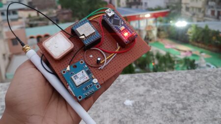
The ability of the GPS module to synchronize signals with satellites is affected by the device’s environmental conditions, especially whether the module is inside or outside during use.
Once the GPS module is able to connect to a satellite, the OLED screen will display the speed in kilometers per hour (or mph) using an Analog Gauge format.
When the device is stationary or not in motion, the gauge may show zero speed. It is important to note that the accuracy of the speed readings can be influenced by factors such as signal strength, satellite visibility, and environmental conditions.



1 Comment
Hi,
Great prjoect,
I want to build this for myself, but i need extra info on the screen: Max Speed.
So i want to see the max speed, let say i put the gps in a RC car, and i run it for 2 minutes, bring the car back to me, then i want to see on the little screen what the max speed was.
Is this possible?