Are you passionate about drones and looking to create your own advanced flight controller? In this complete guide, we will guide you through the step-by-step process of building a high-performance drone flight controller using a Raspberry Pi Pico. With this controller, you’ll possess the skill to control your drone with accuracy and even extend its distance for unlimited experiences in the sky.
Whether you’re new to drone building or a scholar, this project will advance you to supercharge your drone flights to the next level. Let’s start!
Required Components
Before diving into the build, ensure you have all the necessary components ready:
- Raspberry Pi Pico\
- Raspberry Pi Zero
- MPU6050 Module
- QMC5883L Module
- GPS Module
- Raspberry Pi Camera
- Drone Frame
- Motors, ESCs, and propellers
- Power supply and connectors
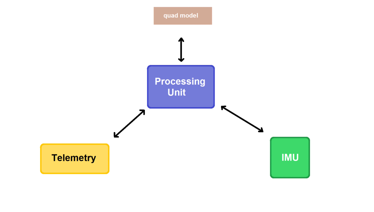
A flight controller is like the brain of a drone. It has important parts, such as sensors, communication tools, and a microcontroller that controls all the sensors. To start this project, I needed to pick the right microcontroller for this job. At first, I thought about using STM boards, but something unexpected happened. My friend told me about the Raspberry Pico, and I decided to use it instead of STM.
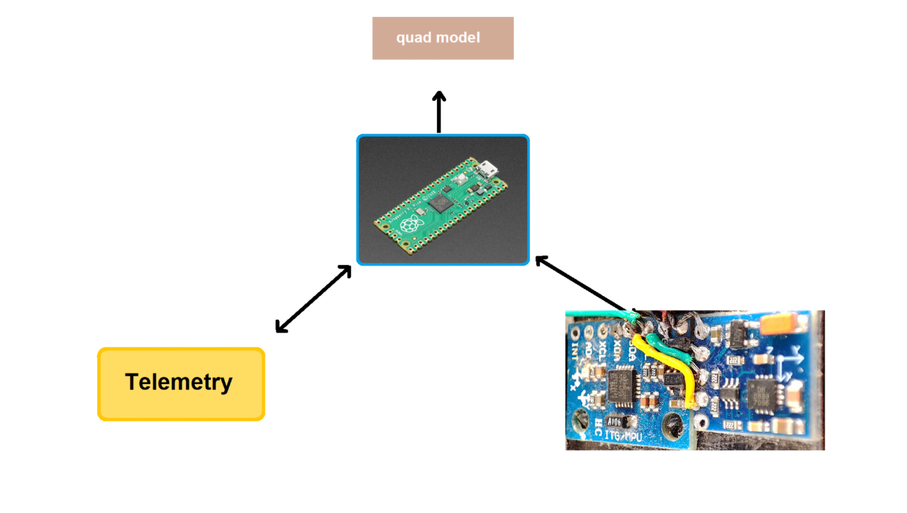
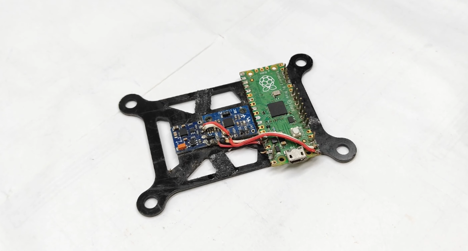
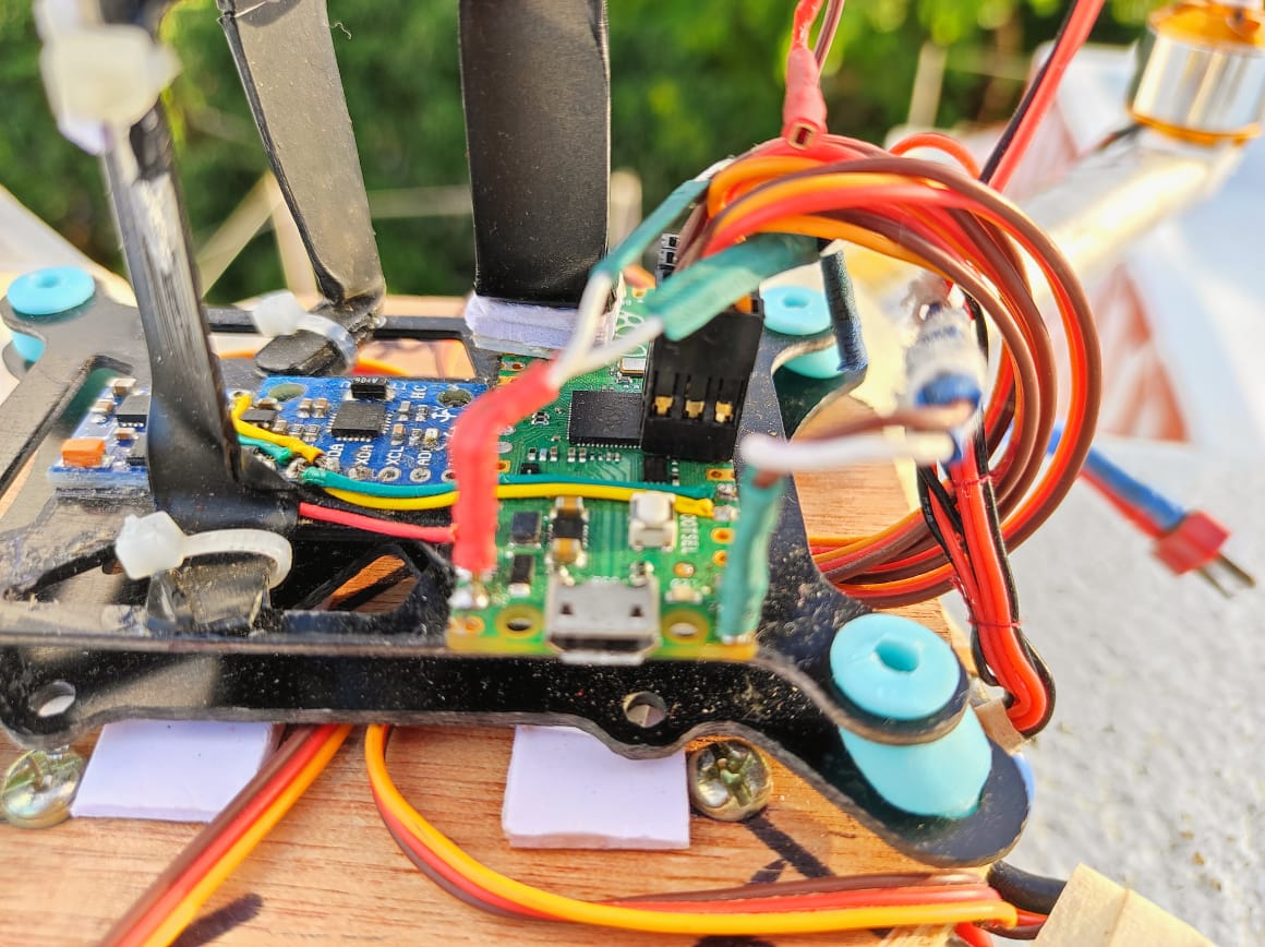
For the Inertial Measurement Unit (IMU), which helps the drone know how it’s moving, I initially decided to use the MPU6050 sensors. I attached them securely to the drone using dampeners and connected them to the Raspberry Pico using I2C Connection.
I had previously built a basic ESP8266 flight controller, but my fantasy led me to take things to the next level. Here, I Build a flight controller using Raspberry Pi Pico which is equipped with features such as live Video streaming, GPS navigation, a ground control station, and much more.
Drone Flight Controller With Raspberry Pi Pico
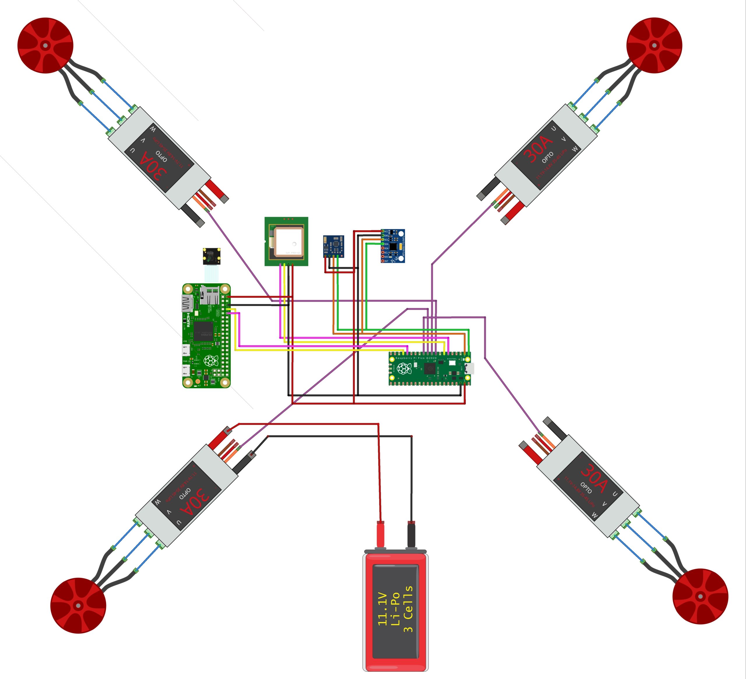
Looking at a circuit photo might seem a bit confusing, but don’t worry! You can easily make the connections by following a simple pin mapping guide. It’s straightforward.
| Sensor & Module | Raspberry Pi Pico Pin Connections |
|---|---|
| MPU6050 | SDA (Data Line) to GPIO Pin 0 |
| SCL (Clock Line) to GPIO Pin 1 | |
| QMC5883L | SDA (Data Line) to GPIO Pin 0 |
| SCL (Clock Line) to GPIO Pin 1 | |
| GPS Module | UART RX (Receive) to GPIO Pin 4 |
| UART TX (Transmit) to GPIO Pin 5 |
Check you connect the sensor wires to the correct GPIO pins on the Raspberry Pi Pico based on the respective data (SDA, SCL, TX, RX) and power needs.
Raspberry Pi Zero To Pi Pico
| Raspberry Pi Zero Pin | Description | Raspberry Pi Pico Pin | Description |
|---|---|---|---|
| 14 (TXD) | Transmit | 13 (RX) | Receive |
| 15 (RXD) | Receive | 12 (TX) | Transmit |
ESC Connection
| ESC Number | Signal Wire (Color) | Raspberry Pi Pico Pin | Ground Wire (Color) | Power Wire (Color) |
|---|---|---|---|---|
| ESC 1 | Orange | GP6 | Black or Brown | Red |
| ESC 2 | Orange | GP7 | Black or Brown | Red |
| ESC 3 | Orange | GP8 | Black or Brown | Red |
| ESC 4 | Orange | GP9 | Black or Brown | Red |
Please note that the GPIO pins mentioned (GP6 to GP9) are general-purpose input/output pins on the Raspberry Pi Pico. Confirm that you have configured these pins correctly in your flight control code for motor control using Pulse Width Modulation (PWM).
Also, double-check the color-coding of the wires from your ESCs as it may vary between different manufacturers.
Build the Frame
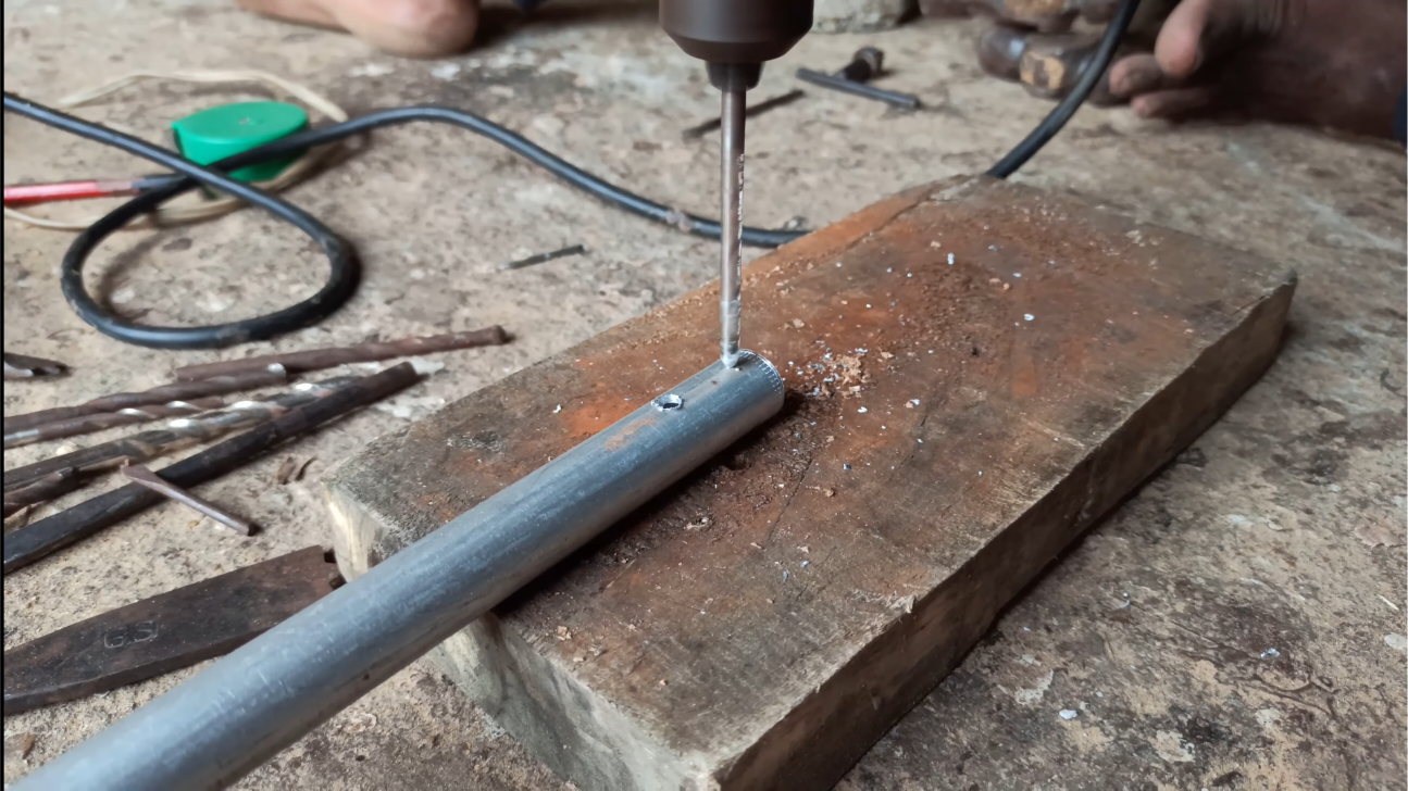
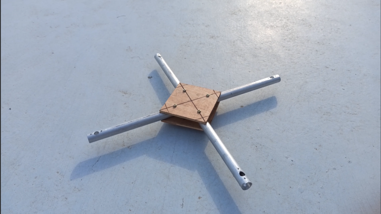
Moving on to the physical build of the drone, To make a suitable frame you are required to use the lightest elements as you can. I needed a super lightweight frame. These aluminum pipes fit perfectly – they’re very light and sturdy, making them perfect for use as the drone’s arms. To attach the motors, I drilled the necessary holes in the pipes.
For keeping the arms securely in place, I opted for plywood boards. I took two of these boards and fastened them on both sides with screws. This step added strength without adding much weight, which is crucial for a drone. The Ultimate Guide to How To Build a Drone At Home
Connect Motors and ESCs
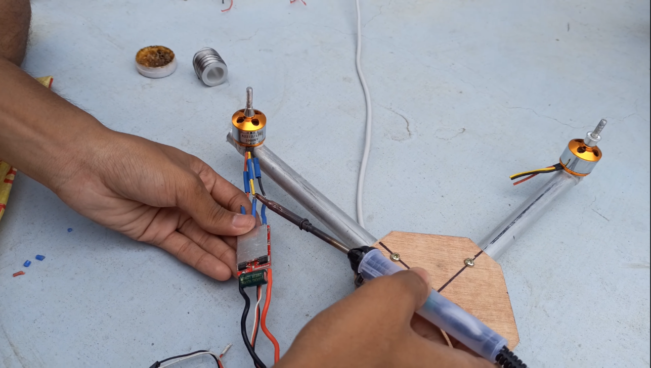
Attach the motors to the frame, and make sure they are securely attached. You can use strings and glue for added stability. Solder the Electronic Speed Controllers (ESCs) to the motors.
As for soldering the Electronic Speed Controllers (ESCs), it turned out to be a straightforward task.
Putting the Circuit on the Frame
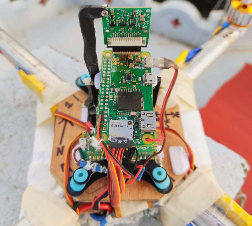
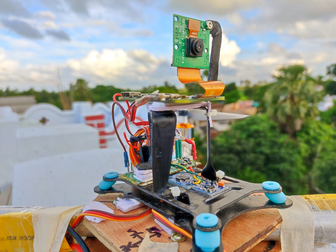
Securely attach the Raspberry Pi Pico, sensors, and components to the drone frame, ensuring balance and stability. secure the power source, and protect the circuitry if needed.
Implement the Extended Kalman Filter (EKF)
In my previous NodeMCU flight controller, I used to face the tough challenge of every time calibrating sensors before every flight, which often resulted in inaccurate data during the flight. This was frustrating because it wasn’t a problem I observed with commercial drones. The solution to this problem came in the form of the Extended Kalman Filter (EKF), This filter will predict the attitude quaternion using angular velocity data from the gyroscope and then refine this prediction using accelerometer and magnetometer readings.
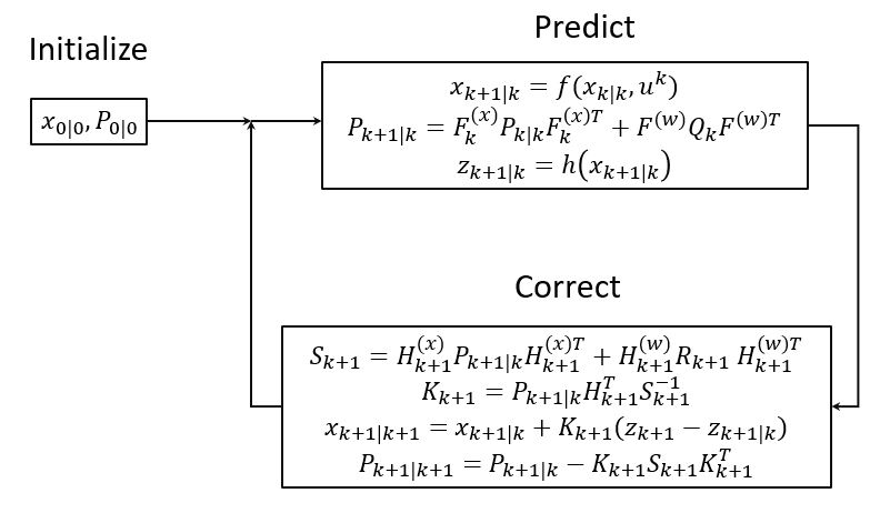
The most special part of the EKF is that I can no longer manually calculate and modify the gyro bias by taking multiple readings and serving averaging and subtraction. The filter itself autonomously calculates and minimizes sensor bias. Although I was still required to perform calibration for the magnetometer and a bit of adjustment for the accelerometer, this was a one-time process.
I wrote the necessary code for all these calculations and, as a result, transformed my IMU from providing unreliable data to delivering accurate and stable measurements.
Programming:
Develop the flight code for your Raspberry Pi Pico. The code collects data from the sensors, uses the EKF for orientation estimation, and calculates the required motor speed using a PID controller. This code allows your drone to move exactly as you like.
Now, we can add some cool features like making the drone hold its position (position hold), preventing it from flying too low (altitude hold), and other flying tricks.
PWM Control
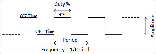
We Use Pulse Width Modulation (PWM) to control the motor speeds. Raspberry Pi Pico simplifies PWM setup, and you can use its abilities to fine-tune motor control. Since the EKF process takes about 4.5 milliseconds, we use a PWM period of 5 milliseconds to keep things synchronized.
Raspberry Pi Pico has 8 separate PWM channels, each controlling 2 PWM channels. We’ve included their PWM library, configured the clock settings, and set 5 milliseconds.
GPS Integration
You can use a GPS module to provide accurate latitude and longitude information for your drone in your device. This is important for navigation and tracking.
To make the drone move the way we want, we have to manage its “attitude,” which decides how it tilts and accelerates. To control this attitude, we use a tool called a PID controller.
Neo M8N GPS works well. It sends position information in the form of NMEA sentences via UART, connected to the UART1 port of the Pico. To ensure the smooth process of the flight code, I’ve used Direct Memory Access (DMA) to copy data directly from the UART peripheral to memory, minimizing processor involvement.
The GPS module operates at a 10Hz update frequency and transmits only the necessary NMEA sentences. I’ve added a counter to run a function every 100 milliseconds, while the main flight code continues to run at 200Hz. Within this function, I decode the NMEA sentences, extract latitude, longitude, and satellite count, fix data, and then transmit this GPS data to our app.
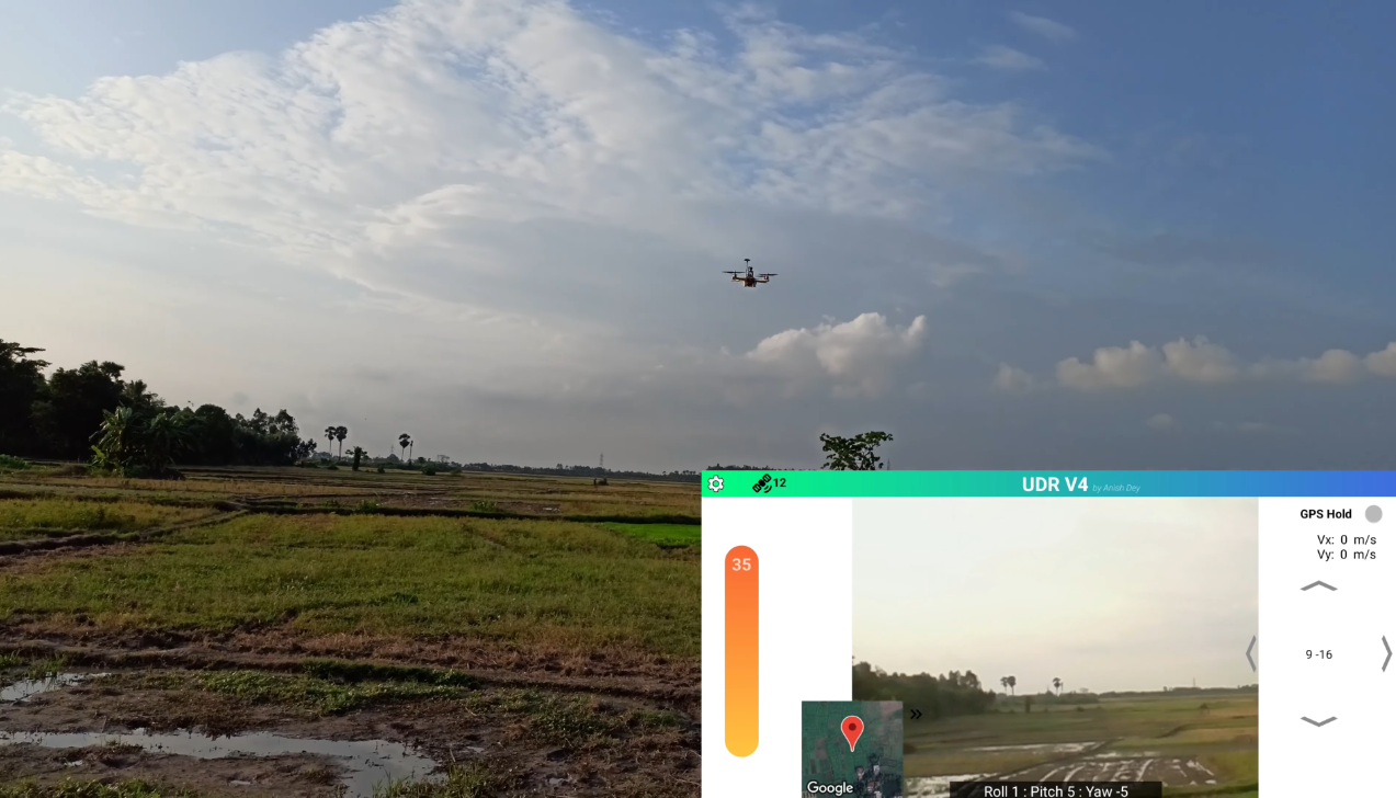
Including an element and Google Maps API, the app successfully displays the drone’s live location on a map.
Communication
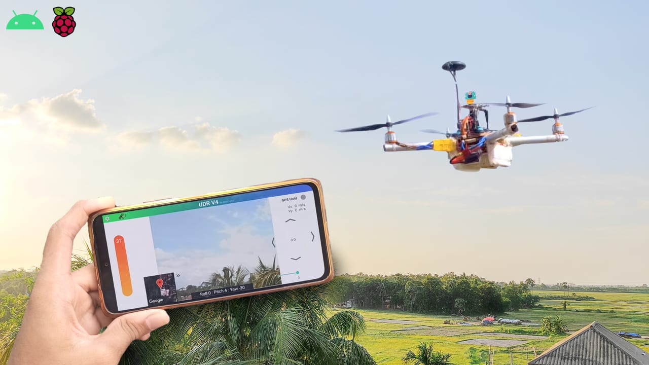
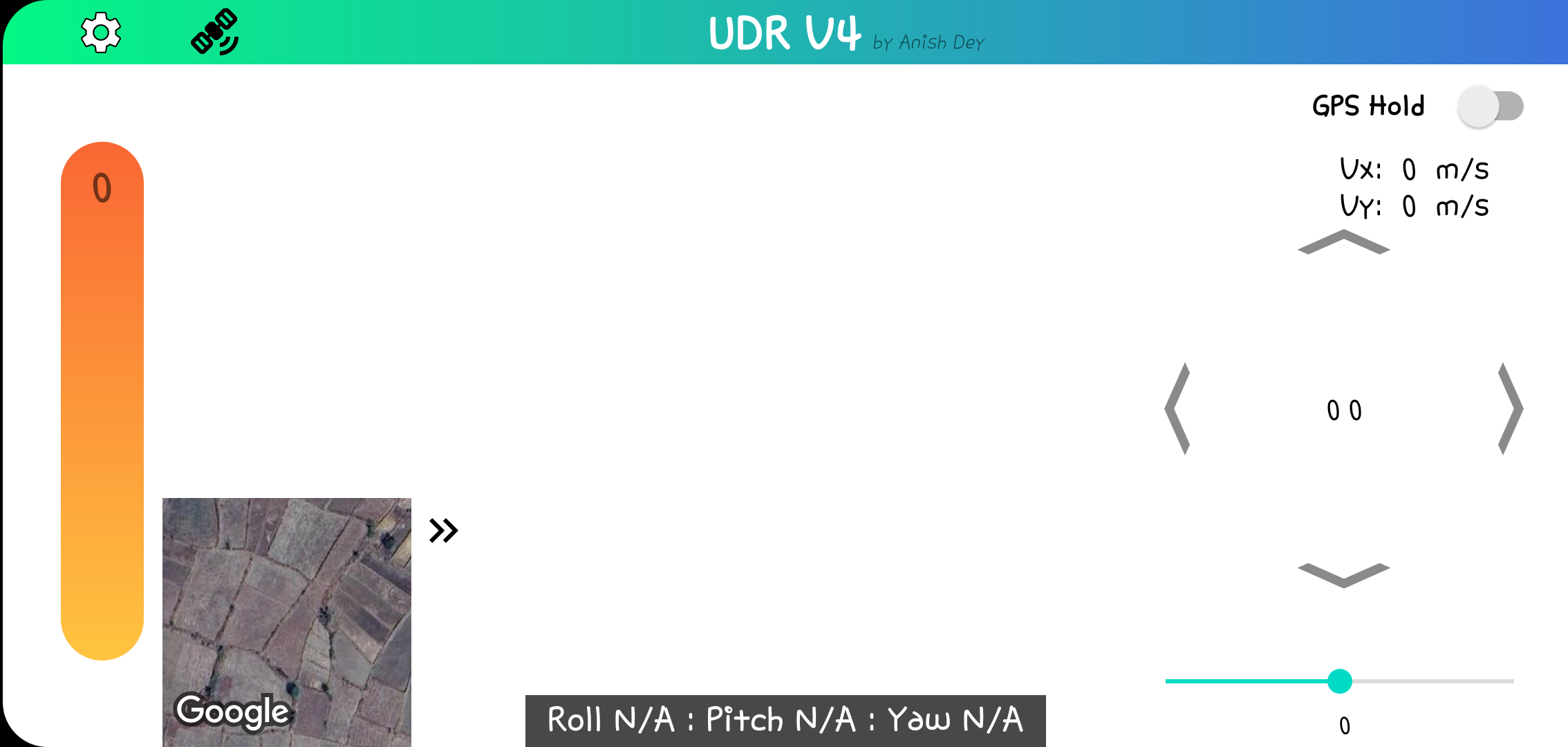
Communication is important for making the drone do what it wants. I made an Android app to control it, which is more practical than using a remote control. With the app, I can see real-time data from the drone, watch live video from its camera, and track its location on a map using GPS.
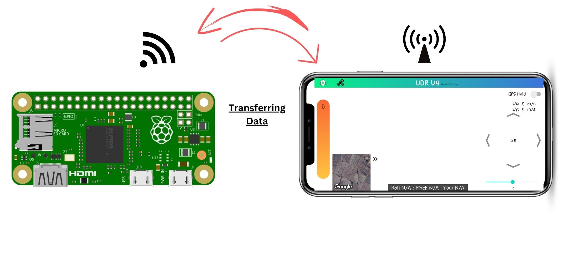
The Pico reads the incoming data, processes it, and sends back some data to the Pi. I’m using a high baud rate, so interrupting the main loop for a brief moment doesn’t have a significant impact. Once this cycle is complete, the Pi communicates with the app via TCP, exchanging data.
Code & Libraries
Apologies, but this time the code is not available for free like ESP8266 Drone due to limited YouTube revenue. However, you can still build your drone with our drone package
- Fly Package
- What You Get:
- Runnable Files: These files are ready to run on your Raspberry Pi Zero. You can’t change the code but can fly your drone.
- Android APK: An app for controlling the drone.
- Wiring Diagram: A visual guide to help with connections.
Pro Package:
- What You Get:
- All Codes: Full source codes for Raspberry Pi Pico and Raspberry Pi Zero, plus runnable files. You can make changes to customize your drone.
- Android Studio Codes: Source codes for the control app and the APK for your Android device.
- Wiring Diagram: A visual guide for assembly.
- Instruction PDF: Step-by-step instructions for drone assembly, Pico setup, and app connection.
- What You Get:
Buy Pico Drone Software Packages
I appreciate your understanding and happy flying!
Android App for Raspberry Pi Pico Flight Controller
Create an Android app for controlling your drone. This app will allow you to receive real-time data from the drone, and live video streaming, and even you can track its location on a map. You can use Android Studio for app development.
For the Android app, I’m using Android Studio. I’ve designed the layout and written the code to handle TCP communication. The app sends joystick data in the form of a character array and receives data in a similar manner.
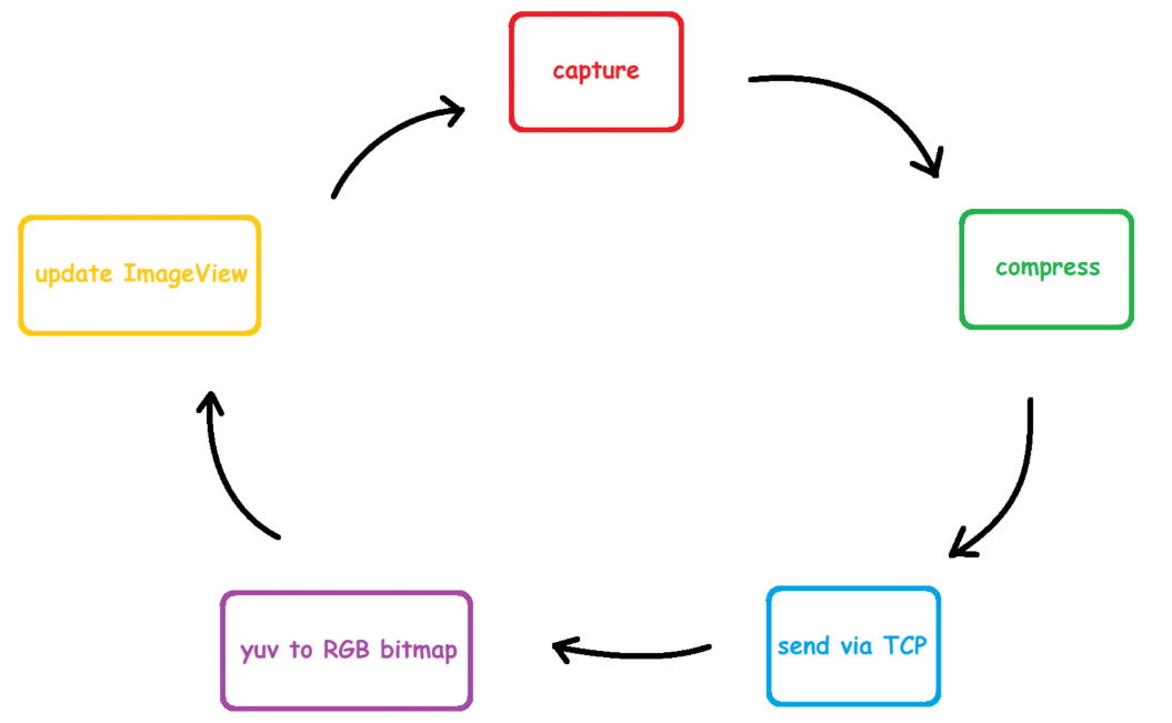
Now, let’s talk about live video streaming. I’ve attached a camera to the Pi, which runs a C++ script to capture RGB image data in an array format and sends it to the Android app through another TCP socket. The app displays the video using a Bitmap within an image. This cycle repeats, creating the illusion of continuous video streaming.
However, there’s a challenge. The video has a resolution of 640×480 pixels, and each pixel contains 24 bits of data, resulting in a large amount of data to transmit.
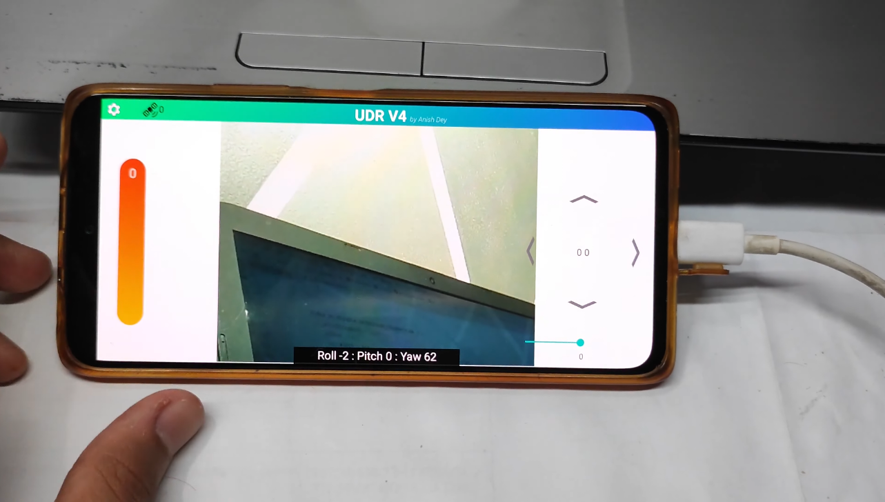
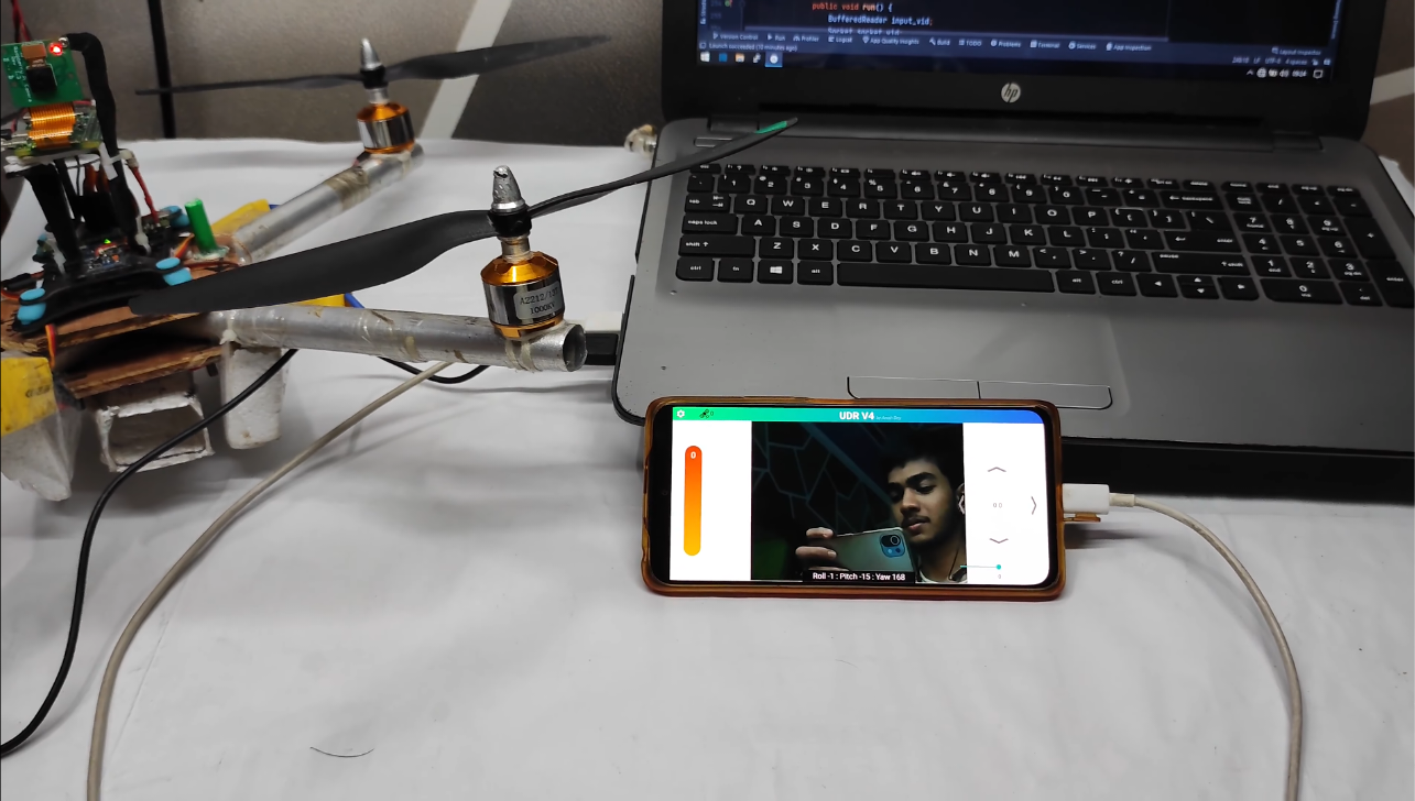
To address this, rather than sending raw RGB values, I’ve adopted the YUV420p format. This format compromises color information but reduces data size by half while maintaining good image quality. The video streaming works well with this setup you can see the below image.
Happy Flying!
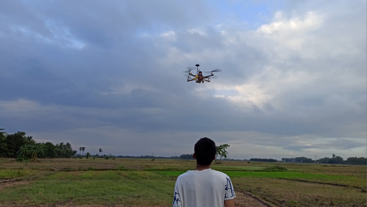
Start up your drone and enjoy your flight.
Fine-Tuning Altitude Control
To maintain altitude, employ a PID controller for the throttle. This ensures your drone can hold its position effectively.
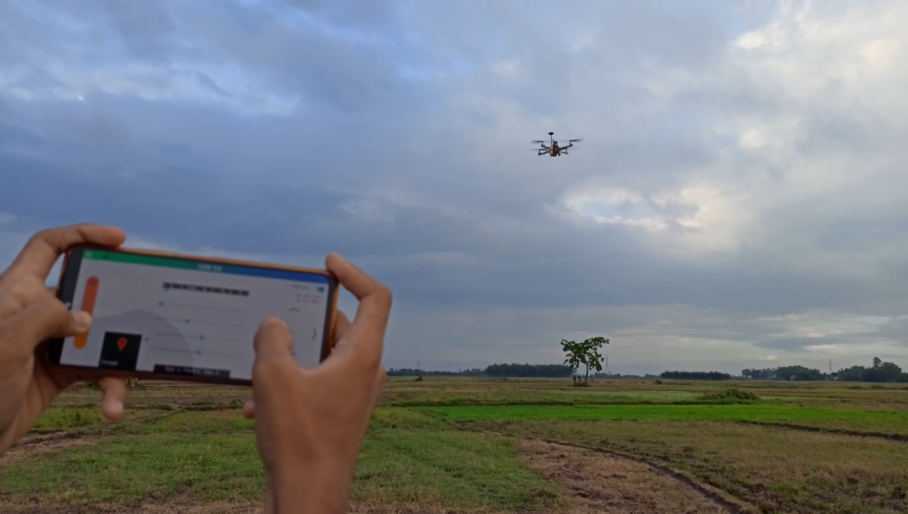
Performing Unlimited Range
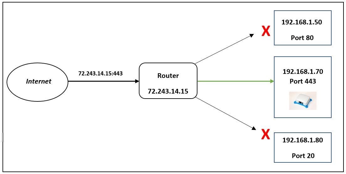
Originally, you could use Wi-Fi for communication, but for an unlimited range, consider placing a portable small router on your drone and configuring port forwarding. This will allow you to control your drone over the internet with minimal latency.

