Overview
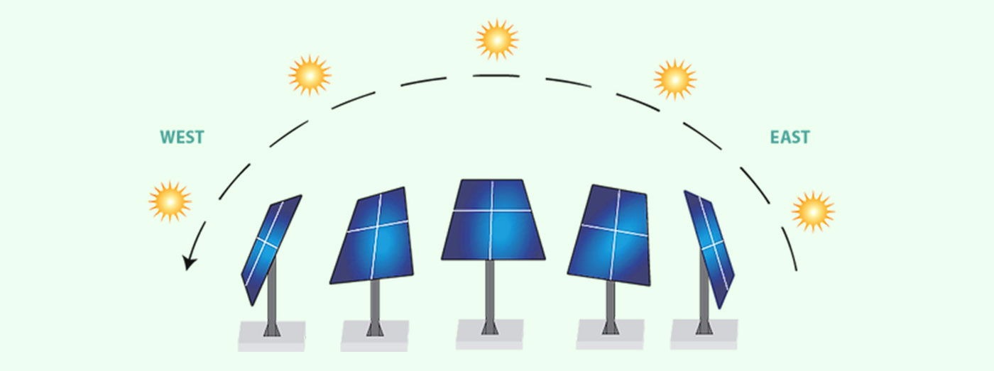
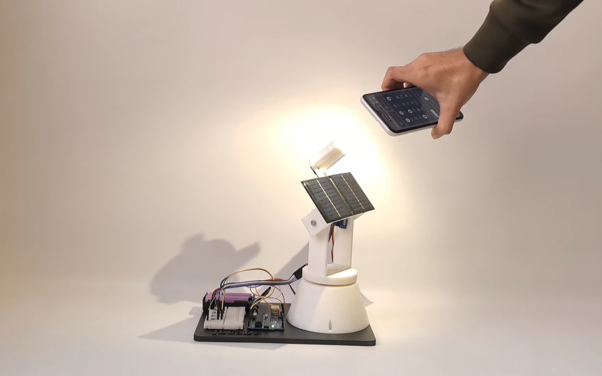
In this tutorial, we build a small dual-axis Arduino Solar Tracker Project system that improves solar panel power output by aligning them with the sun throughout the day. To achieve optimal alignment, the system uses an Arduino, light-dependent resistors (LDRs), servo motors, and a solar panel.
Solar panels have long been recognized as a renewable energy source, but their adoption meets challenges due to fairly low efficiency. Polycrystalline solar panels generally operate with efficiencies varying from 15% to 22%.
However, efficiency can be significantly enhanced by dynamically modifying the panel’s direction to follow the sunlight throughout the day. In current years, the price of solar panels has decreased by 30% to 40%, making them more affordable and beneficial.
Solar tracking manages efficiency challenges by allowing photovoltaic (PV) methods to always align with the sunlight path from sunrise to sunset. This process confirms that the panels capture more solar radiation for a longer period compared to fixed solar systems.
Studies show that solar trackers can boost energy output by 30% to 60% yearly. Using a dual-axis tracker, which adjusts both the horizontal and vertical angles, can further boost power generation by up to 40%.
What is a Dual axis solar tracker system?
An Dual Axis Solar Tracker System adjusts the position of solar panels to track the Sun’s movement both vertically and horizontally. This allows the panels to catch the maximum amount of sunlight in the day, improving their efficiency in generating electricity. It ensures the solar panels always face the Sun directly.
There are three main types of solar panel systems:
- Static (Fixed) Panels
- Single-Axis Trackers
- Dual-Axis Trackers
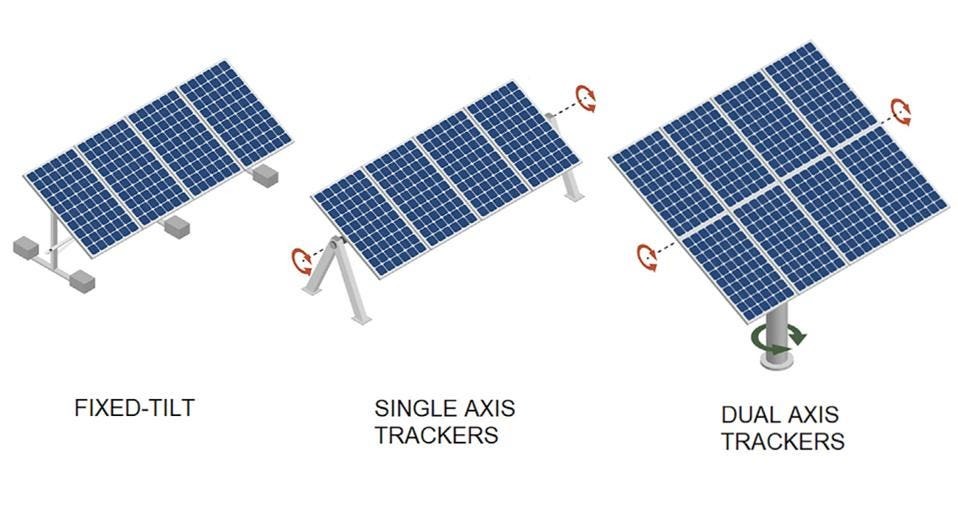
This tutorial project focuses on designing and implementing a high-efficiency dual-axis Arduino Solar Tracker Project. Checkout Latest projects
- Vehicle Monitoring With MCP2515 CAN Bus & Arduino
- DIY Arduino GPS Tracker Project Build Your Location Tracking System
- Getting Started with ESP32 UWB DW3000 Board Ultra-Wideband
Required Materials
- Arduino Uno
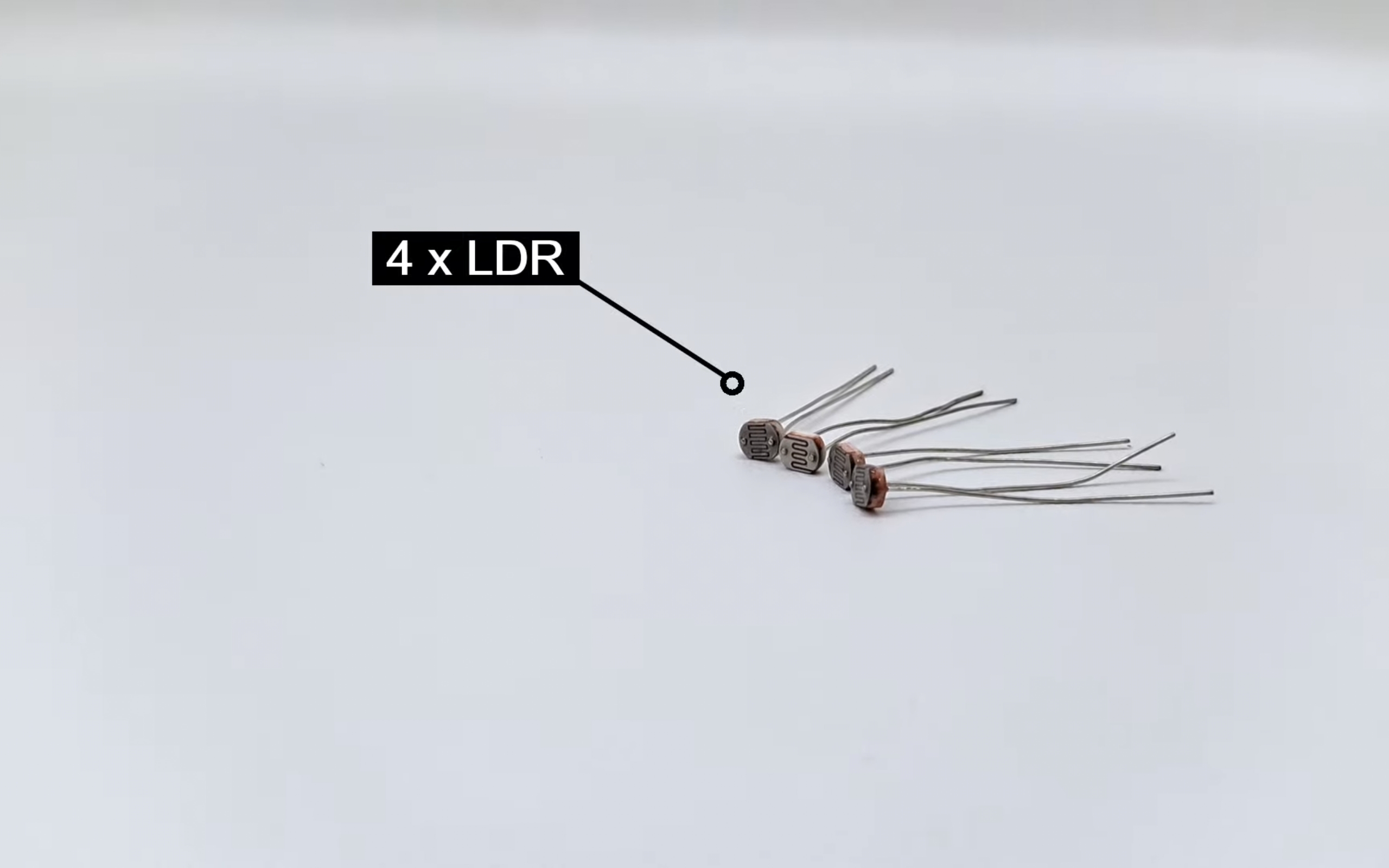
- LDR sensors – 4 pieces.
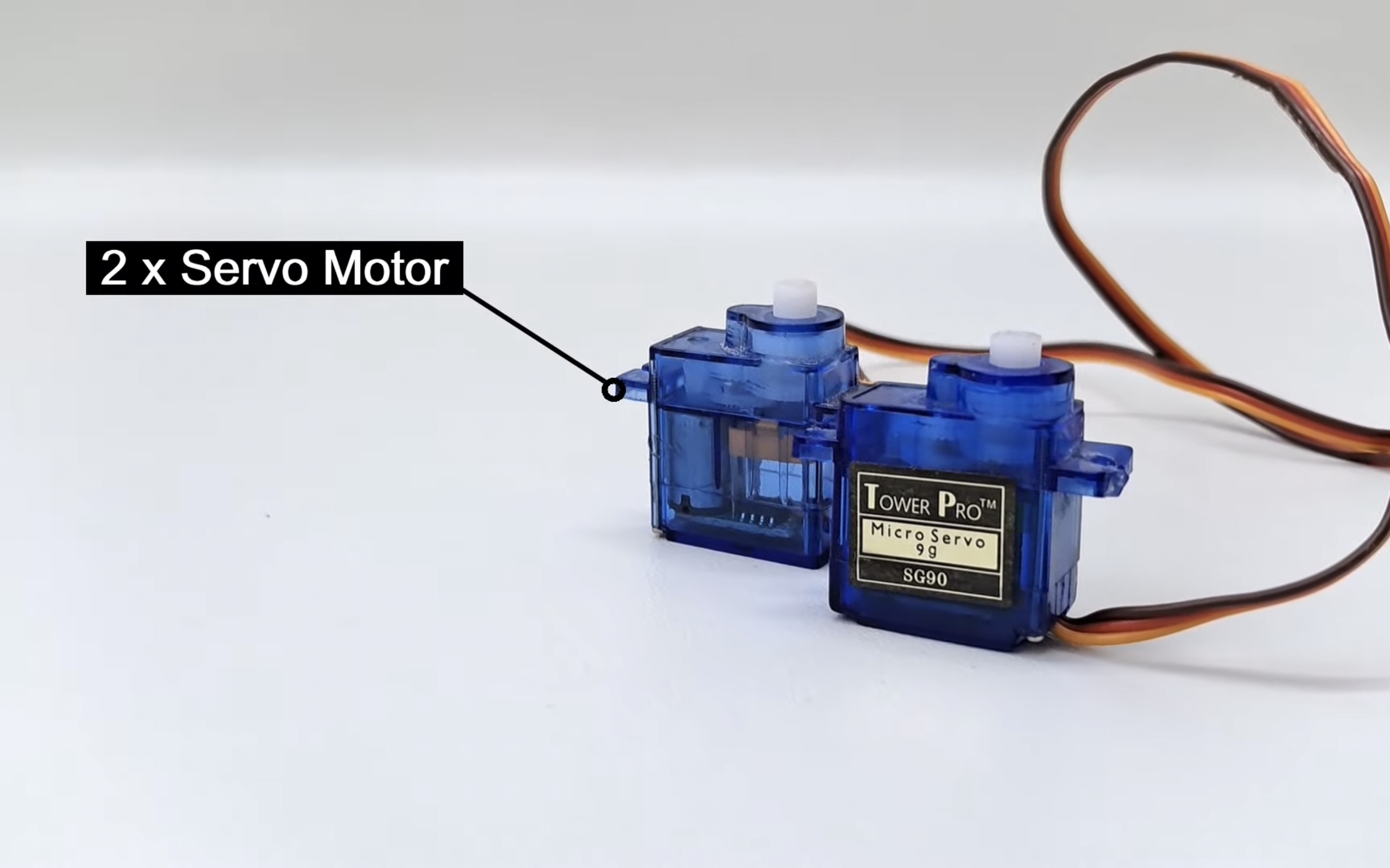
- Servo motors – 2.
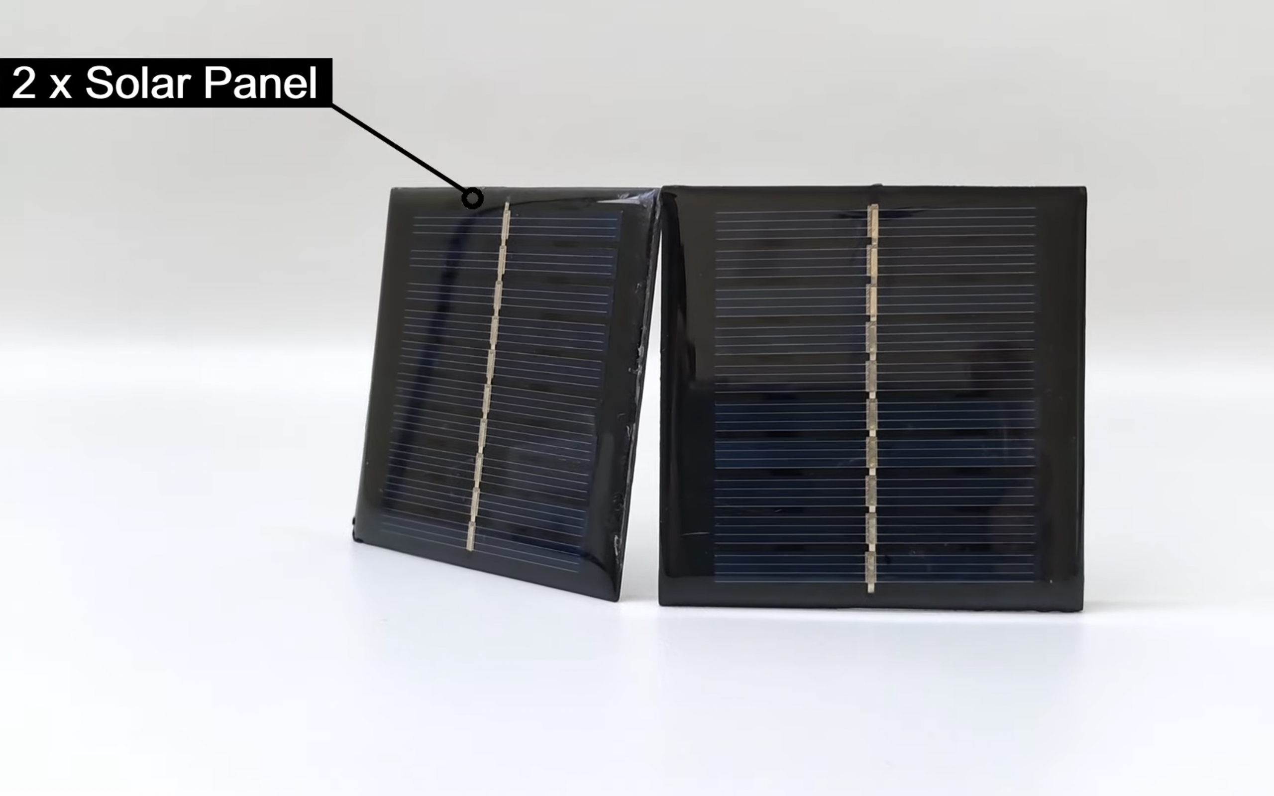
- Solar panel
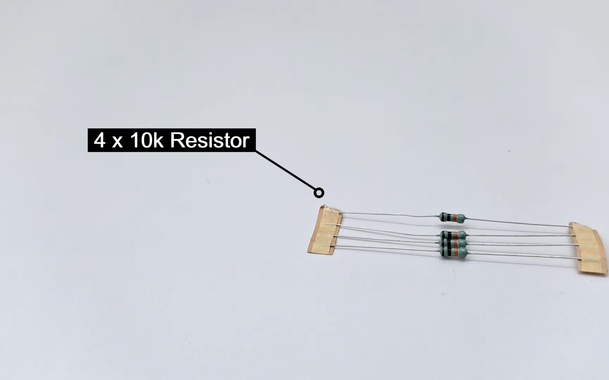
- 10k Resistors
- wires.
- Breadboard.
- Power supply.
Solar tracker using Arduino Circuit diagram.
The circuit for the Dual Axis Solar Tracker is straightforward. We’ve used the A0, A1, A2, and A3 analog pins (APIO) to collect data from the four LDRs (Light Dependent Resistors).
The DPIO pins 2 and 13 are connected to the servo motors, which control the solar panel’s movement. According to the source code, the analog pins of the LDR sensors collect light-intensity signals.
3D Print the Dual Axis Arduino Solar Tracking Project Parts!
The key to this project is having a compact structure to mount solar panels on. One great option is to 3D print the structure. We highly recommend this 3D Printed dual-axis tracker, which can be downloaded Axis Arduino Solar Tracker STL.
Connecting all the parts- Arduino Solar Tracker
Start by attaching the servos to their mounts. Open the servo package, and set aside the small machine screw.
Attach the servo to the bottom of this piece using the two screws.
For the second mount, repeat the process with the second servo, securing it with the screws.
LDR Placement: Mount four LDRs on two axis (for example, horizontal) and the other two on the other axis (vertical).
Connecting All Electronics
- LDR Sensors:
- Top Left (A0) → Pin A0 on Arduino.
- Top Right (A1) → Pin A1 on Arduino.
- Bottom Left (A2) → Pin A2 on Arduino.
- Bottom Right (A3) → Pin A3 on Arduino.
- Servo Motors:
- Horizontal Servo (D2) → Digital Pin 2 on Arduino.
- Vertical Servo (D13) → Digital Pin 13 on Arduino.
Connect each LDR in series with a 10kΩ resistor to form a voltage divider. Attach the resistor’s free end to GND, and connect the center (LDR-resistor) to an analog pin.
Arduino dual-axis solar tracker code
Copy the following code and upload it to your Arduino using the Arduino IDE:
|
1 2 3 4 5 6 7 8 9 10 11 12 13 14 15 16 17 18 19 20 21 22 23 24 25 26 27 28 29 30 31 32 33 34 35 36 37 38 39 40 41 42 43 44 45 46 47 48 49 50 51 52 53 54 55 56 57 58 59 60 61 62 63 64 65 66 67 68 69 70 71 72 73 74 75 76 77 78 79 |
#include <Servo.h> // Define Servo objects for horizontal and vertical motors Servo horizontal; // Horizontal Servo Motor Servo vertical; // Vertical Servo Motor // Initial positions and limits for servos int servohori = 180; // Initial position for horizontal servo int servohoriLimitHigh = 175; // Upper limit for horizontal servo int servohoriLimitLow = 5; // Lower limit for horizontal servo int servovert = 45; // Initial position for vertical servo int servovertLimitHigh = 100; // Upper limit for vertical servo int servovertLimitLow = 1; // Lower limit for vertical servo // LDR pin connections (analog pins) int ldrlt = A0; // Top-left LDR int ldrrt = A3; // Top-right LDR int ldrld = A1; // Bottom-left LDR int ldrrd = A2; // Bottom-right LDR void setup() { // Attach servos to their respective pins horizontal.attach(2); vertical.attach(13); // Set initial positions for servos horizontal.write(180); vertical.write(45); delay(2500); // Allow time for servo initialization } void loop() { // Read LDR values int lt = analogRead(ldrlt); // Top-left LDR int rt = analogRead(ldrrt); // Top-right LDR int ld = analogRead(ldrld); // Bottom-left LDR int rd = analogRead(ldrrd); // Bottom-right LDR int dtime = 10; // Delay time for servo movement int tol = 90; // Tolerance for detecting significant light differences // Calculate averages of LDR readings int avt = (lt + rt) / 2; // Average of top LDRs int avd = (ld + rd) / 2; // Average of bottom LDRs int avl = (lt + ld) / 2; // Average of left LDRs int avr = (rt + rd) / 2; // Average of right LDRs // Calculate differences in light intensity int dvert = avt - avd; // Vertical difference (top vs. bottom) int dhoriz = avl - avr; // Horizontal difference (left vs. right) // Adjust vertical servo if difference exceeds tolerance if (abs(dvert) > tol) { if (avt > avd) { servovert++; // Move up if (servovert > servovertLimitHigh) servovert = servovertLimitHigh; } else { servovert--; // Move down if (servovert < servovertLimitLow) servovert = servovertLimitLow; } vertical.write(servovert); // Update vertical servo position } // Adjust horizontal servo if difference exceeds tolerance if (abs(dhoriz) > tol) { if (avl > avr) { servohori--; // Move left if (servohori < servohoriLimitLow) servohori = servohoriLimitLow; } else { servohori++; // Move right if (servohori > servohoriLimitHigh) servohori = servohoriLimitHigh; } horizontal.write(servohori); // Update horizontal servo position } delay(dtime); // Small delay between movements } |
Modifying the Code:
- Sensitivity:
To adjust how sensitive the tracker is to light changes, modify thetol(tolerance) variable. Lowering the value makes it more sensitive; increasing it makes it less sensitive:
|
1 |
int tol = 90; // Change this to adjust sensitivity |
- Servo Speed:
Change the delay between movements by adjusting thedtimeVariable:
|
1 |
int dtime = 10; // Smaller values make the servos move faster |
Upload the Code – Dual Axis Arduino Solar Tracker Project Using LDR & Servo Motors
copy the above code and paste it into IDE then Click Upload to load the code onto the Arduino.
Testing and Working
Common Issues and Solutions:
- Not working in sunlight:
Check if it’s plugged into a USB power source. The tracker relies on USB power. - Servos moving violently:
Re-home the servos and set servo limits, either manually or in the code. - Limited movement:
Use a flashlight in a dim room. Sunlight can overwhelm the sensors. - Arduino upload error:
Ensure drivers are installed, select “Arduino Uno” from the board’s list, and choose the correct communication port.


