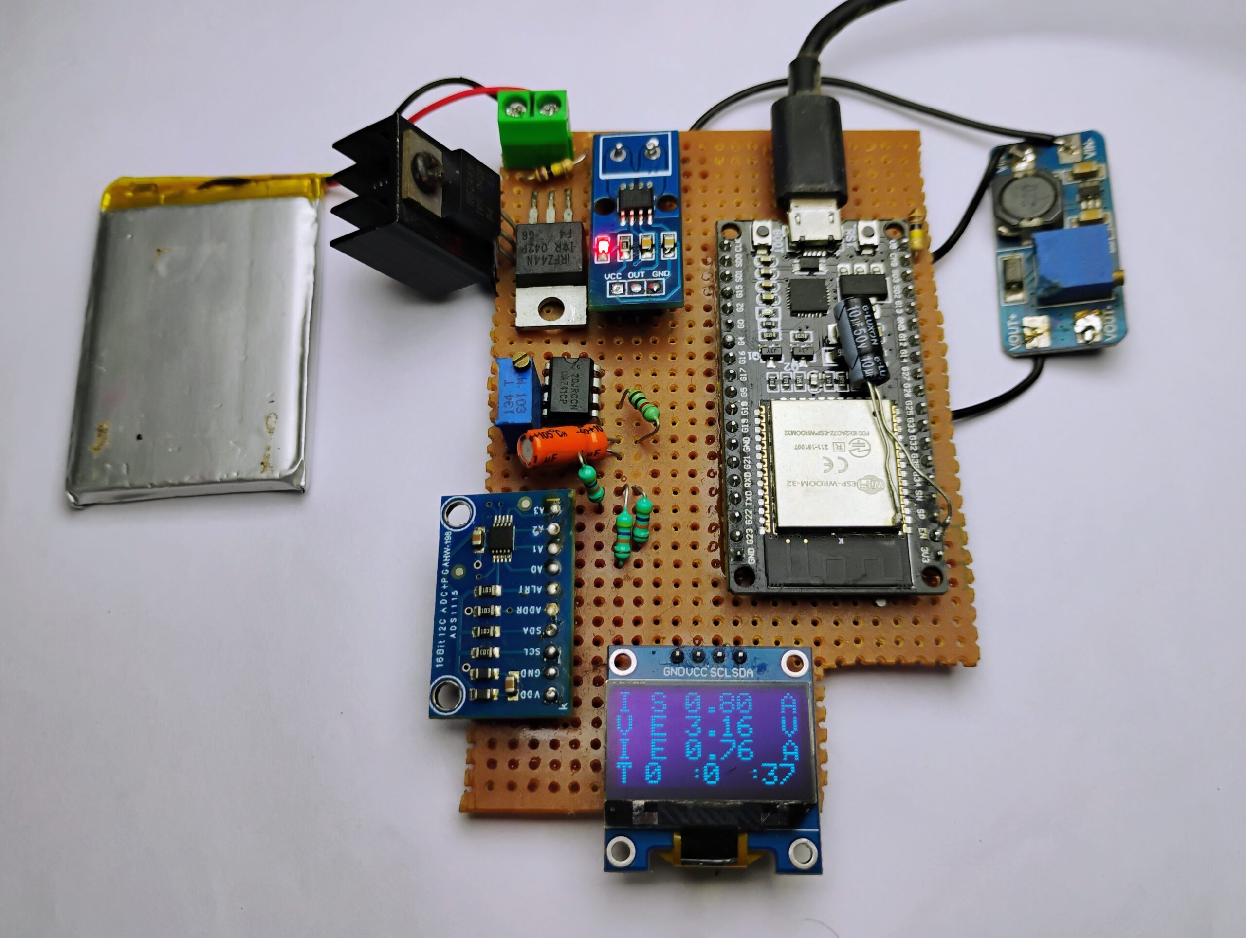
Hey there, today we’re building a power monitoring system. This system can measure voltage, current, and power drawn from the supply, offering features such as accurate current measurement, and voltage measurement up to 12V DC and beyond, real-time calculation of instantaneous power, and advanced functionality to calculate battery capacity under specific loads. Check out the previous post on Arduino Energy Meter Using INA219 DC Current Sensor
Additionally, it’s packed with safety features like reverse voltage protection over-current protection, and fast switching with a dedicated Mosfet driver. Get ready to monitor your energy usage like a pro!
Thank You, PCBWay
This project is completed because of the support and help from PCBWay. If you have a PCB project, please see their website and get exciting deals and coupons.
PCBway is the best prototype PCB company offering great PCB boards at lower prices If you sign up using this link you will get a free coupon or rewards for your first order. https://www.pcbway.com
This system can measure voltage, current, and power drawn from the supply. Some of the salient features of the device include the following :
- Current measurement
- Voltage measurement up to 12V can be expanded further
- Instantaneous power calculation and energy consumption*
- Calculate the battery capacity from a particular load.
- Reverse voltage protection
- Fast switching using the dedicated Mosfet driver
- Over-voltage protection, over-current protection
- Under voltage protection
Required Components
- ESP32 board
- Current sensors
- Jumper wires
- Ads1115 Module
- Acs712 Current Sensor
Hall effect
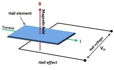
We are measuring current using a Hall effect sensor, Hall effect sensors work by measuring the voltage generated in a semiconductor due to the Lorentz force on electrons, which is proportional to the magnetic field. Since the magnetic field is proportional to the current flowing, the sensor provides us with a simple equation to measure current accurately, with correction factors already handled by the manufacturer.
ACS712 Current Sensor
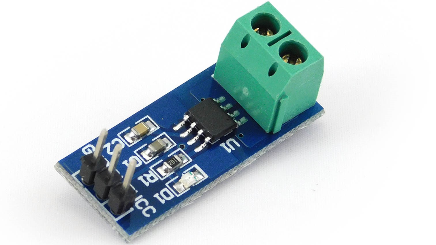
The ACS712 is an accurate current sensor with a Hall sensor circuit and conductive copper track. When current passes through it, it generates a magnetic field detected by the integrated Hall IC, producing a proportional voltage.
The sensor provides accurate readings with low resistance (~1.2 mΩ) and electrical isolation up to 2.1 kV RMS. The 30A version accepts currents up to 30A, offering a proportional analog voltage output (66 mV/A) with an output error of ±1.5% It operates in 4.5V to 5.5V systems. For more on the ACS712 sensor, visit the site. For a clearer explanation of the Hall effect sensor’s operation, go here
Warning! This product is intended for use below 30V. Working with higher voltages can be extremely dangerous and should only be handled by qualified people with proper tools and protective equipment.
Key Features:
- Low-noise analog signal path.
- Provides 2.1 kV RMS isolation voltage.
- Operates on a single 5.0V supply.
- Output sensitivity ranges from 66 to 185 mV/A.
- Proportional output voltage for both AC and DC currents.
- Scale Factor
- The sensitivity for ACS712
| 5A Module | 20A Module | 30A Module |
| 185mV/Amp | 100mV/Amp | 66mV per Amp |
ACS712 Circuit Design & Schematic:
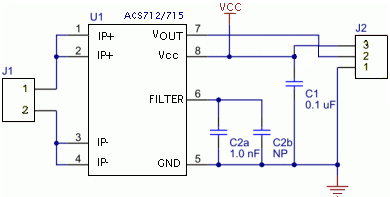
The practical connection diagram is straightforward and clear. It simply requires connecting the sensor in series with the load whose current consumption we want to measure.
When there’s no current passing through the sensor, it reads a value that’s not exactly zero.
Here’s why: Arduino’s analog ports use an A/D converter that ranges from 0 to 1023, where 0 equals 0V and 1023 equals 5V. Since the sensor detects both positive and negative currents, its output voltage is at 2.5V (VCC/2) when there’s no current, resulting in an Arduino reading close to 512.
Positive currents increase the reading, while negative currents decrease it. The output sensitivity can be obtained from the ACS712-Datasheet As per the datasheet, the sensitivity is 66mV / A
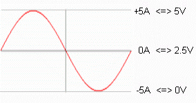
For instance, if the sensor measures currents between -5A and +5A, the output ranges from 0V to 5V, with 2.5V corresponding to 0A. Each ampere variation corresponds to 185mV.
This sensor can handle both DC and AC currents. In an AC waveform, the lowest point corresponds to -5A, where the output is at 2.5V (0A), and the highest point corresponds to +5A, reaching 5V.
Theory
In a nutshell, we are using an ESP32 as the main microcontroller to do all the calculations with ADS115 ADC Converter to measure all the analog voltage levels and Acs712 hall effect current sensor, Using this current sensing method is better than using a resistor to measure voltage because it doesn’t cause any voltage drop across the sensor. and hence the power of the device under load is not altered.
In this setup, I’ve connected the ACS712 to the ADS1117 instead of the ESP32’s analog pin. This choice was made due to the ADS1117’s excellent resolution and better linear voltage-current curve than the ESP32 Analog pins. How To Use ADS1115 16-Bit ADC with ESP32
Here, we’re using N-channel FETs with extremely low resistance, around 20 milliohms. This means there’s hardly any power loss in the switching components, so we don’t need heatsinks, and power loss is kept to a minimum.
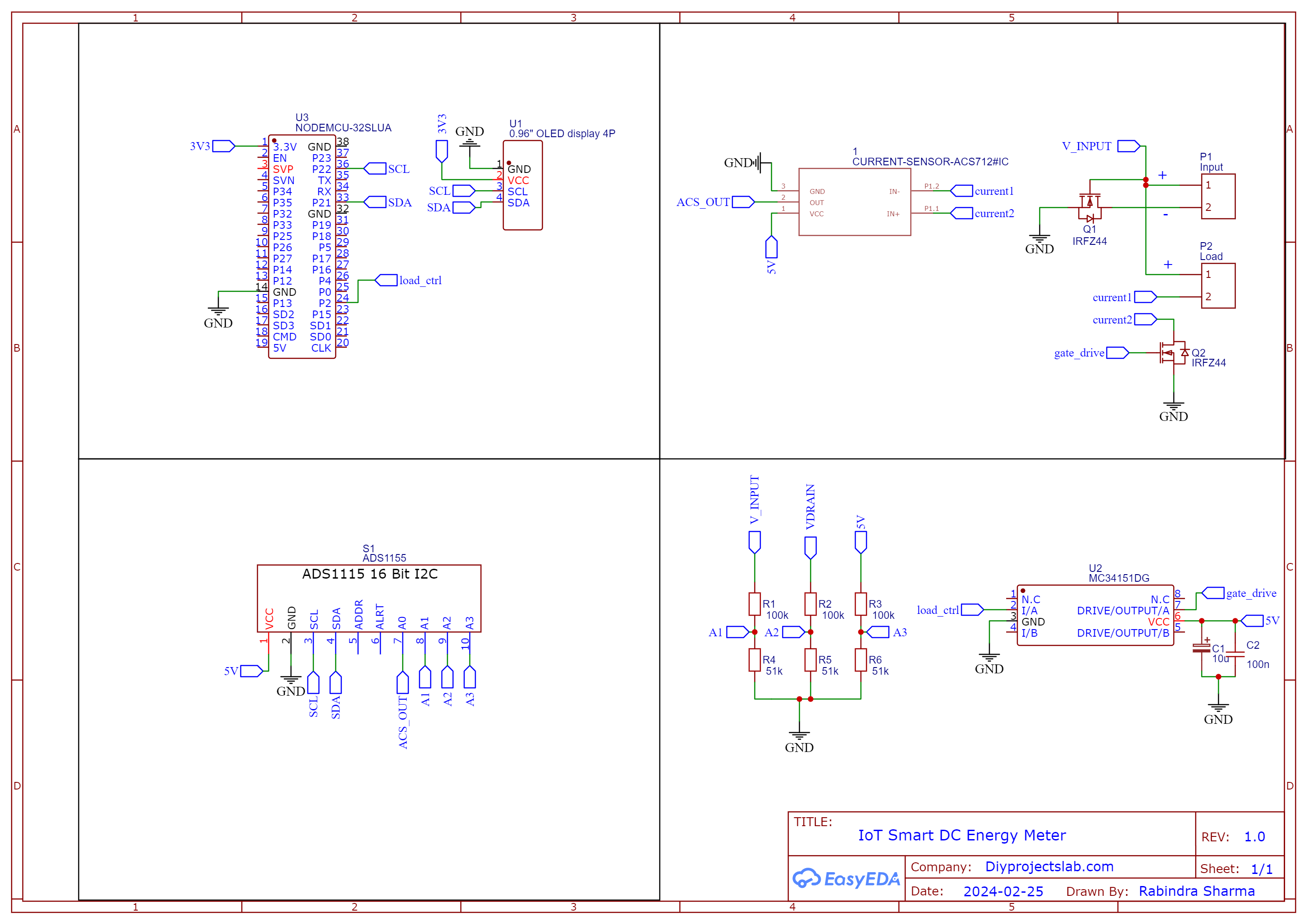
Schematics IoT Smart DC Energy Meter with ESP32 & ThingSpeak
ESP32: Central processing unit collecting sensor data, performing calculations, and controlling the OLED display.
ACS712 Current Sensor: Measures current by converting magnetic field into a proportional voltage. ESP32 reads voltage and calculates current.
Voltage Divider: Containing two resistors, the MCU reads and converts to actual voltage, enabling measurement of voltages higher than the esp32 analog input limit.
OLED Display: Visualizes real-time data, communicating with ESP32 via I2C protocol. Displays voltage, current, power, and energy meter readings.
Setting up Thingspeak
ThingSpeak offers excellent IoT tools. Through its website, users can monitor data and control systems online using ThingSpeak’s Channels and web pages. To get started, sign up for an account at https://thingspeak.com.
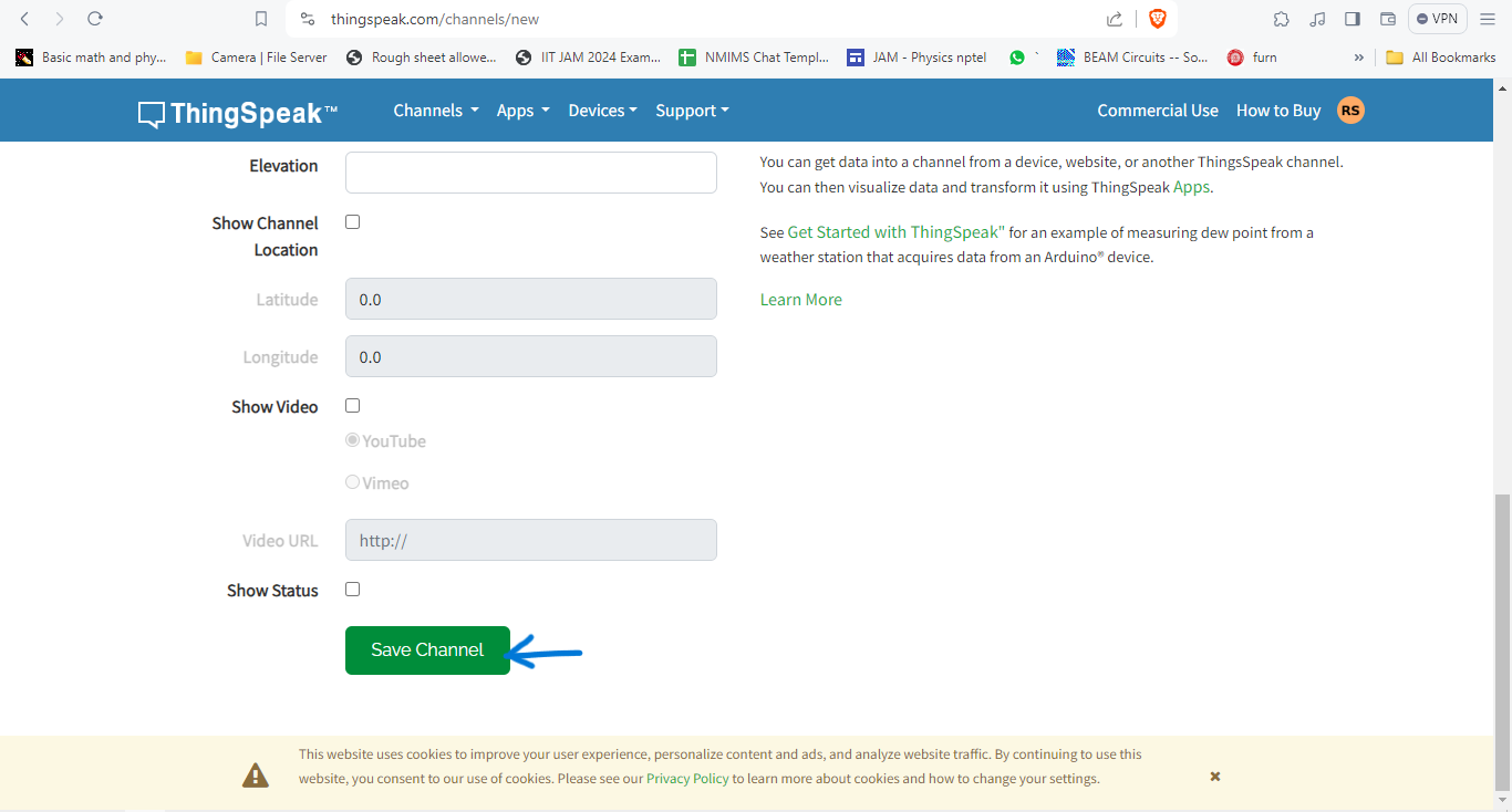
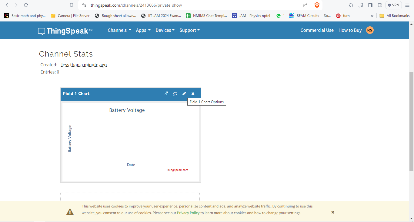
Now click on channels so that you can see the online data streaming.
We need to create three parameters for measuring Voltage, Current, and Power, here Sample data was sent using a potentiometer as a voltage source.
Prepare Hardware
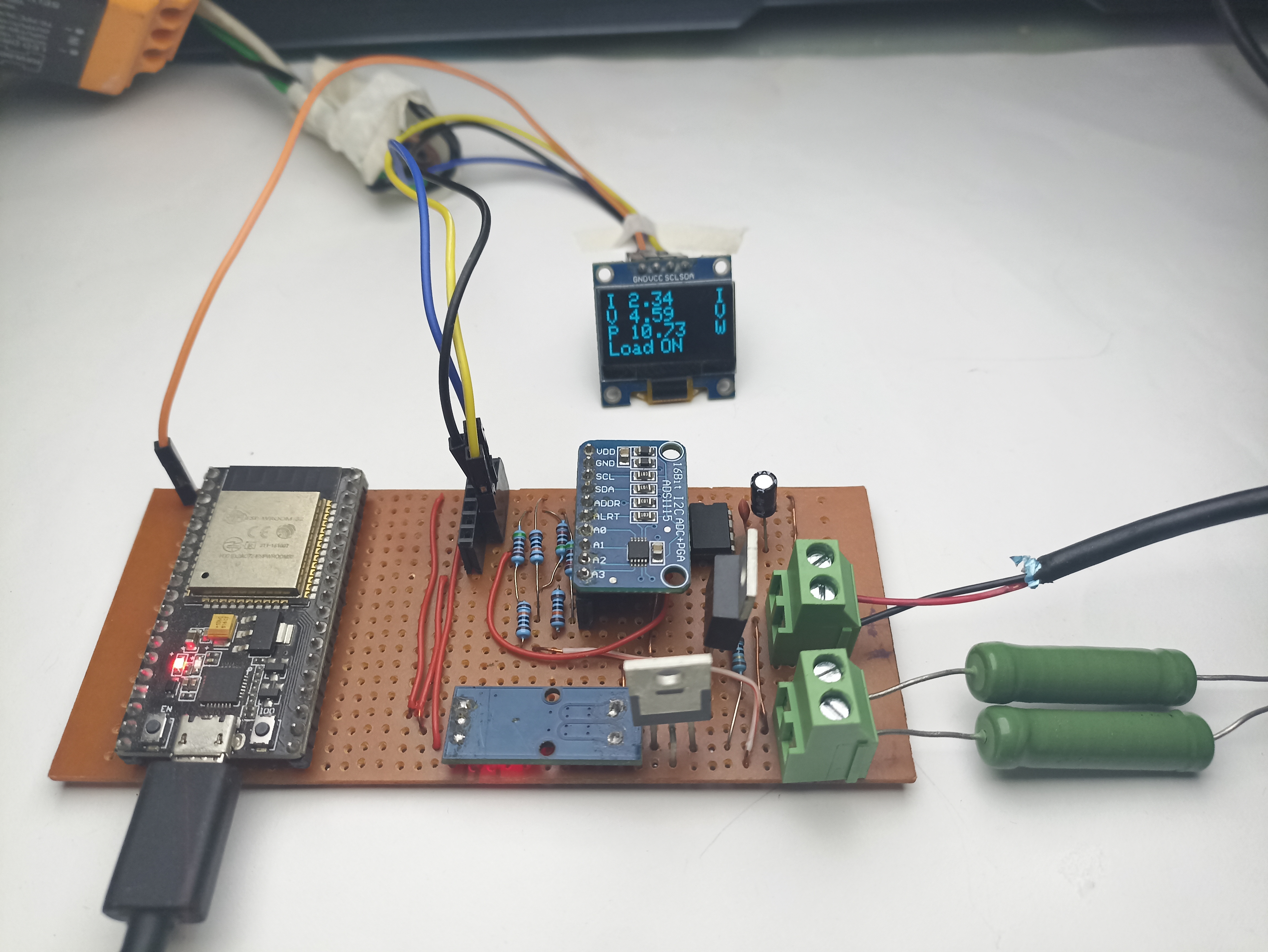
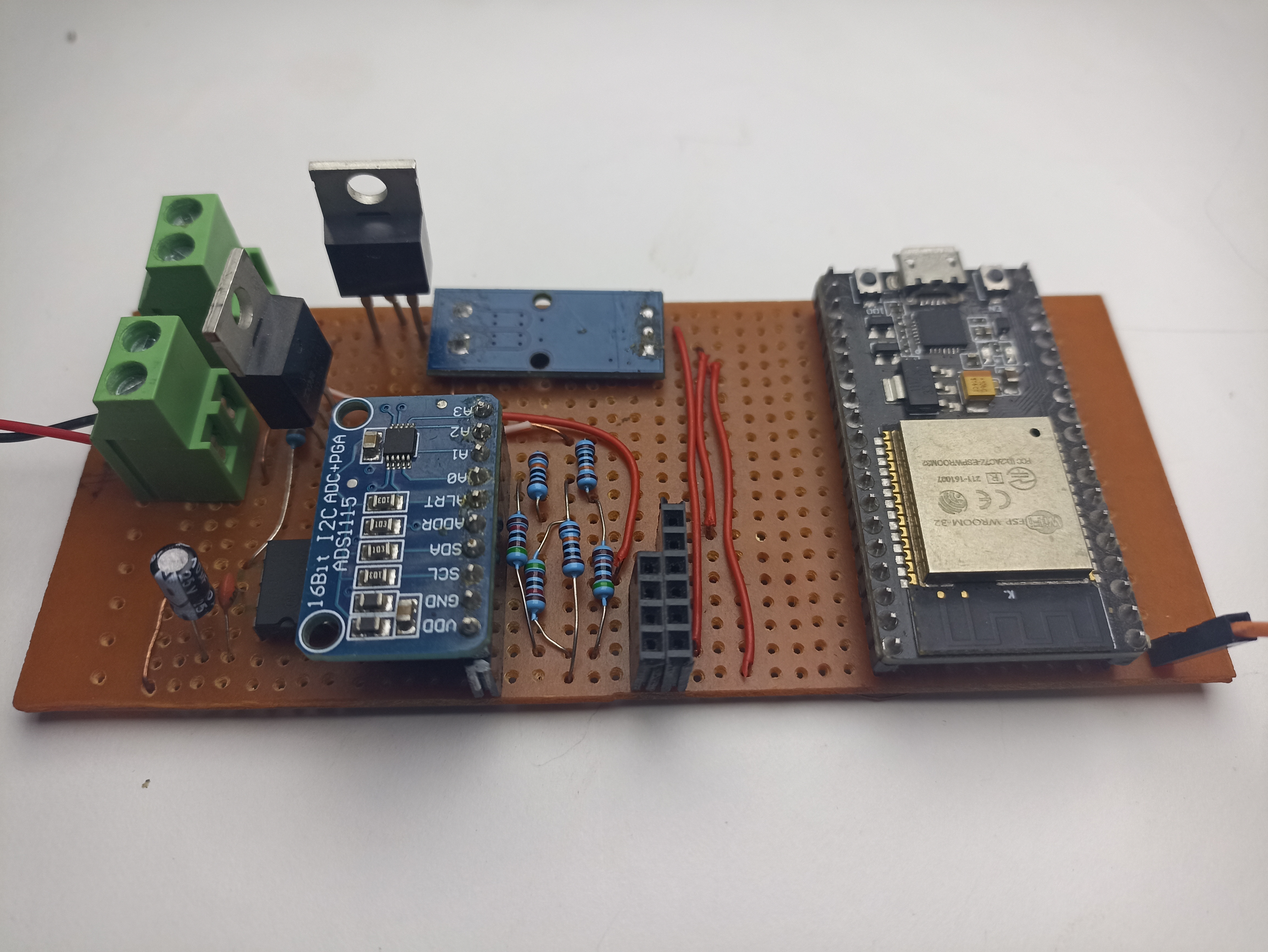
To keep everything organized, I made a custom circuit board using a Zero PCB board. First, I attached male header pins to the ESP32 board. Then, I soldered female headers onto the prototype board to easily connect the OLED Display and different components.
Finally, I soldered a 4-pin screw terminal to the power supply unit and load for input DC supply.
Source Code and Libraries:
To use the XIAO ESP32 board with the Arduino library, you’ll need the Arduino IDE with ESP32 board support. You can easily add this support by following Sparkfun’s tutorial.
Library Installation
Before uploading the code, make sure to install these libraries:
- Adafruit_ADS1X15
- Adafruit_SSD1306
- ThingSpeak
Source Code
Before uploading the code, ensure that you have installed all the required libraries from the provided links. Then, copy the code below and upload it to the ESP32 board.
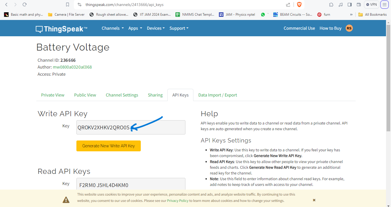
From the following lines, change the WiFi SSID, Password & Thingspeak API Key.
|
1 2 3 |
const char* ssid = "Note 10s"; // your network SSID (name) const char* password = "abcd1234"; // your network password const char * myWriteAPIKey = "3F0KV2XHSKTQRO0S"; |
Here is a complete code for this project.
|
1 2 3 4 5 6 7 8 9 10 11 12 13 14 15 16 17 18 19 20 21 22 23 24 25 26 27 28 29 30 31 32 33 34 35 36 37 38 39 40 41 42 43 44 45 46 47 48 49 50 51 52 53 54 55 56 57 58 59 60 61 62 63 64 65 66 67 68 69 70 71 72 73 74 75 76 77 78 79 80 81 82 83 84 85 86 87 88 89 90 91 92 93 94 95 96 97 98 99 100 101 102 103 104 105 106 107 108 109 110 111 112 113 114 115 116 117 118 119 120 121 122 123 124 125 126 127 128 129 130 131 132 133 134 135 136 137 138 139 140 141 142 143 144 145 146 147 148 149 150 151 152 153 154 155 156 157 158 159 160 161 162 163 164 165 166 167 168 169 170 171 172 173 174 175 176 177 178 179 180 181 182 183 184 185 186 187 188 189 190 191 192 193 194 195 196 197 198 199 200 201 202 203 204 205 206 207 208 209 210 211 212 213 214 215 216 217 218 219 220 221 222 223 224 225 226 227 228 229 230 231 232 233 234 235 236 237 238 239 240 241 242 243 244 245 246 247 248 249 250 251 252 253 254 255 256 257 258 259 260 261 262 263 |
// AUTHOR: Rabindra Sharma // // URL:https://diyprojectslab.com/ #include <WiFi.h> #include "ThingSpeak.h" #include "ADS1X15.h" #include <SPI.h> #include <Wire.h> #include <Adafruit_GFX.h> #include <Adafruit_SSD1306.h> #define SCREEN_WIDTH 128 // OLED display width, in pixels #define SCREEN_HEIGHT 64 // OLED display height, in pixels // Declaration for an SSD1306 display connected to I2C (SDA, SCL pins) // The pins for I2C are defined by the Wire-library. // On an arduino UNO: A4(SDA), A5(SCL) // On an arduino MEGA 2560: 20(SDA), 21(SCL) // On an arduino LEONARDO: 2(SDA), 3(SCL), ... #define OLED_RESET -1 // Reset pin # (or -1 if sharing Arduino reset pin) #define SCREEN_ADDRESS 0x3C ///< See datasheet for Address; 0x3D for 128x64, 0x3C for 128x32 #define load_pin 2 Adafruit_SSD1306 display(SCREEN_WIDTH, SCREEN_HEIGHT, &Wire, OLED_RESET); const char* ssid = "Note 10s"; // your network SSID (name) const char* password = "abcd1234"; // your network password const char * myWriteAPIKey = "3F0KV2XHYSTQRO0S"; WiFiClient client; unsigned long myChannelNumber = 1; ADS1115 ADS(0x48); float prevtime = 0 ; float prevtime1 = 0 ; float vol = 0 ; float current_zero_error = -3 ; float input_current = 0 ; float input_voltage = 0 ; float drain_voltage = 0 ; const float voltage_lim = 12.0 ; const float current_lim = 5.0 ; const float uvoltage_lim = 1 ; byte ecode = 0; bool disablewifi = 1 ; bool load_state = 0 ; void disint(); void disdat(); void adc_init(); void measure() ; void setup() { pinMode(load_pin, OUTPUT); digitalWrite(load_pin , load_state); Serial.begin(115200); disinit(); adc_init(); disdat(); // Initialize ThingSpeak prevtime = millis(); prevtime1 = millis(); Wire.begin(); if (disablewifi == 0 ) { WiFi.mode(WIFI_STA); ThingSpeak.begin(client); if (WiFi.status() != WL_CONNECTED) { Serial.print("Attempting to connect"); while (WiFi.status() != WL_CONNECTED) { WiFi.begin(ssid, password); delay(5000); } Serial.println("\nConnected."); } } } void loop() { if ((millis() - prevtime ) > 100) { measure(); disdat(); digitalWrite(load_pin , load_state); prevtime = millis(); } if (((millis() - prevtime1 ) > 30000 ) && disablewifi == 0 ) { ThingSpeak.setField(1, input_current); ThingSpeak.setField(2, input_voltage); ThingSpeak.setField(3, input_current * input_voltage); int x = ThingSpeak.writeFields(myChannelNumber, myWriteAPIKey); if (x == 200) { Serial.println("Data succesfully entered to Server "); } else { Serial.println("Data seding failed"); } prevtime1 = millis(); } } void disinit() { if (!display.begin(SSD1306_SWITCHCAPVCC, SCREEN_ADDRESS)) { Serial.println(F("SSD1306 allocation failed")); for (;;) ; // Don't proceed, loop forever } // Show initial display buffer contents on the screen -- // the library initializes this with an Adafruit splash screen. display.clearDisplay(); display.display(); delay(200); // Pause for 2 seconds // Clear the buffer display.clearDisplay(); display.setTextSize(1); // Normal 1:1 pixel scale display.setTextColor(SSD1306_WHITE); display.setCursor(0, 20); display.println(F(" Diyprojectlabs.com")); display.display(); delay(1000); } void disdat() { Serial.print("dsidat execeuted!"); display.clearDisplay(); delay(1); display.setTextSize(2); display.setCursor(0, 0); display.println(F("I ")); display.setCursor(24, 0); display.println(input_current); display.setCursor(115, 0); display.println("I"); display.setCursor(0, 16); display.println(F("V ")); display.setCursor(24, 16); display.println(input_voltage); display.setCursor(115, 16); display.println("V"); display.setCursor(1, 32); display.println(F("P ")); display.setCursor(24, 32); display.print((input_voltage*input_current)); display.setCursor(115, 32); display.println("W"); display.setCursor(1, 48); display.println(F("Load")); display.setCursor(56, 48); if (load_state == 0 ) { display.println("ON"); } else if (load_state == 1 && ecode == 1 ) { display.println("OCP"); } else if (load_state == 1 && ecode == 2) { display.println("OVP"); } display.display(); } void adc_init() { Wire.begin(); ADS.begin(); ADS.setGain(0); // 6.144 volt } void measure() { int16_t raw_data1 = 0; int16_t raw_data2 = 0; int16_t raw_data3 = 0; raw_data1 = ADS.readADC(1); raw_data2 = ADS.readADC(2); raw_data3 = ADS.readADC(3); float vref = (ADS.toVoltage(raw_data3) * 3 )/2; float AcsValue = 0.0, Samples = 0.0, AvgAcs = 0.0, AcsValueF = 0.0; for (int x = 0; x < 11; x++) { //Get 150 samples AcsValue = ADS.readADC(0); //Read current sensor values Samples = Samples + AcsValue; //Add samples together delay (10); // let ADC settle before next sample 3ms } AvgAcs = Samples / 10.0; //Taking Average of Samples //((AvgAcs * (5.0 / 1024.0)) is converitng the read voltage in 0-5 volts //2.5 is offset(I assumed that arduino is working on 5v so the viout at no current comes //out to be 2.5 which is out offset. If your arduino is working on different voltage than //you must change the offset according to the input voltage) //0.066(66mV) is rise in output voltage when 1A current flows at input AcsValueF = (vref - (ADS.toVoltage(AvgAcs) ) ) / 0.066 - current_zero_error ; input_current = AcsValueF ; input_voltage = ADS.toVoltage(raw_data1) * 3 ; drain_voltage = ADS.toVoltage(raw_data2) * 3 ; Serial.println("------------------------------"); Serial.println((input_current), 3); Serial.println("Current drawn (A)"); Serial.println(input_voltage, 3); Serial.println("Input voltage "); Serial.println(drain_voltage, 3); Serial.println("Drain voltage"); Serial.println("------------------------------"); if (AcsValueF >= current_lim) { ecode = 1 ; //OC digitalWrite(load_pin, HIGH); load_state = 1; } if (input_voltage >= voltage_lim | input_voltage <= uvoltage_lim ) { ecode = 2 ; //OC digitalWrite(load_pin, HIGH); load_state = 1; } } |
From the Board Manager, select the ESP32 Board and the COM port. Then hit the upload button to upload the code to the ESP32 Board.
Code Explanations:
While I can’t provide a detailed explanation of the entire code, I’ll highlight some key parameters for debugging and customization:
Adjust the voltage and current limits using:
|
1 2 |
const float voltage_lim = 12.0; const float current_lim = 5.0; |
These parameters allow you to define the maximum permissible voltage and current levels, tailoring the behavior of the system to your specific requirements.
Toggle WiFi functionality with:
Additionally, you can easily toggle the WiFi functionality on or off using the boolean variable:
|
1 |
bool disablewifi = 1; |
Setting disablewifi to 1 disables the WiFi functionality. This feature is particularly handy for users who prefer offline operation or need to debug their system without connecting to a network.
Upon system initialization, it’s advisable to calibrate the current measurement for accuracy. You can achieve this by utilizing a multimeter to determine the offset value of the current. Adjust the following parameter until the measured current at no load approaches zero:
|
1 |
float current_zero_error = -3; |
Although it’s unnecessary for the current to be exactly zero due to potential sensor inaccuracies, fine-tuning this value enhances the precision of current measurements.
These parameters enable users to customize and optimize system performance for their specific needs.
Field Testing
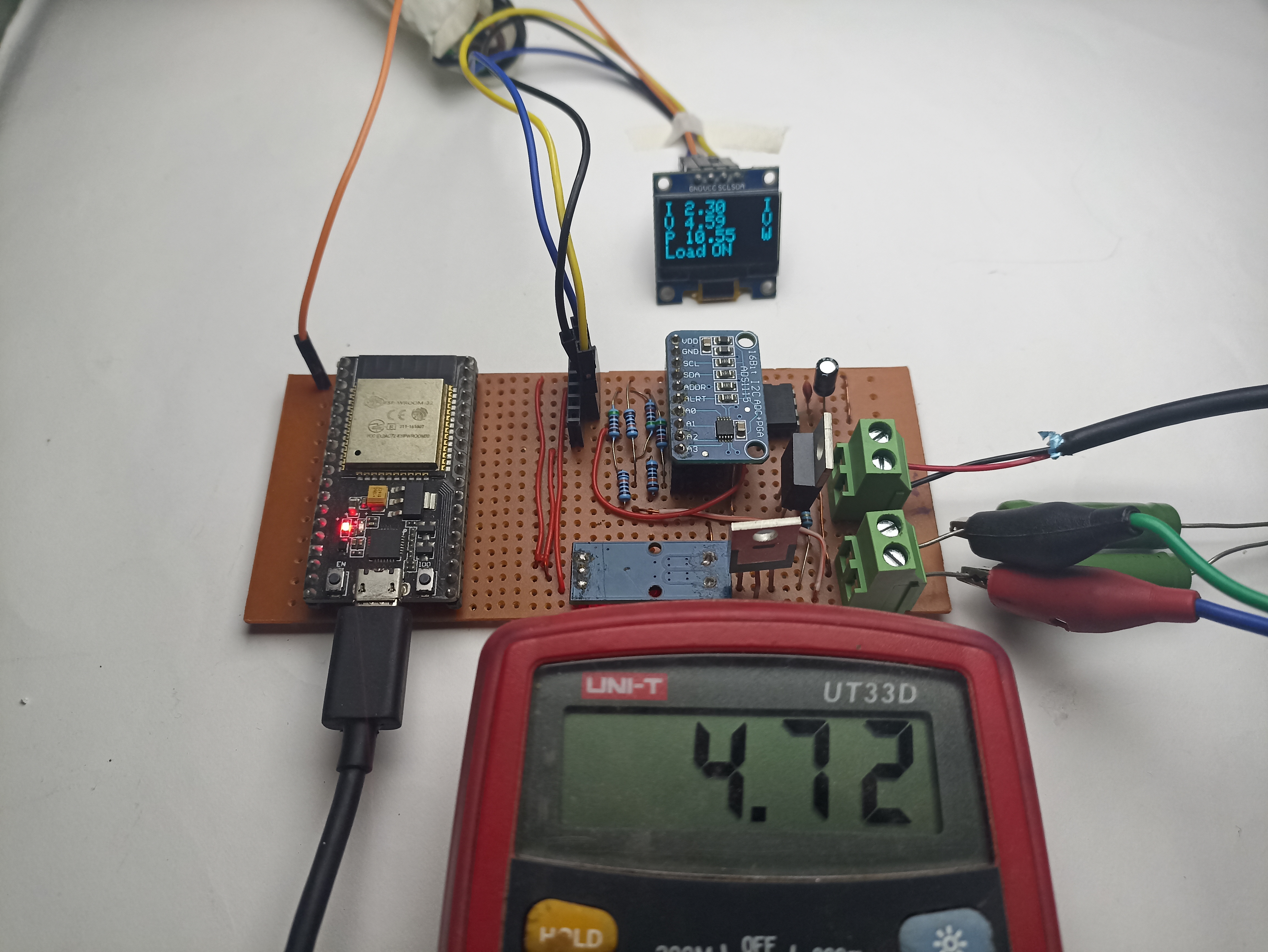
Now that our device is ready for real field testing, the connections should be as follows:
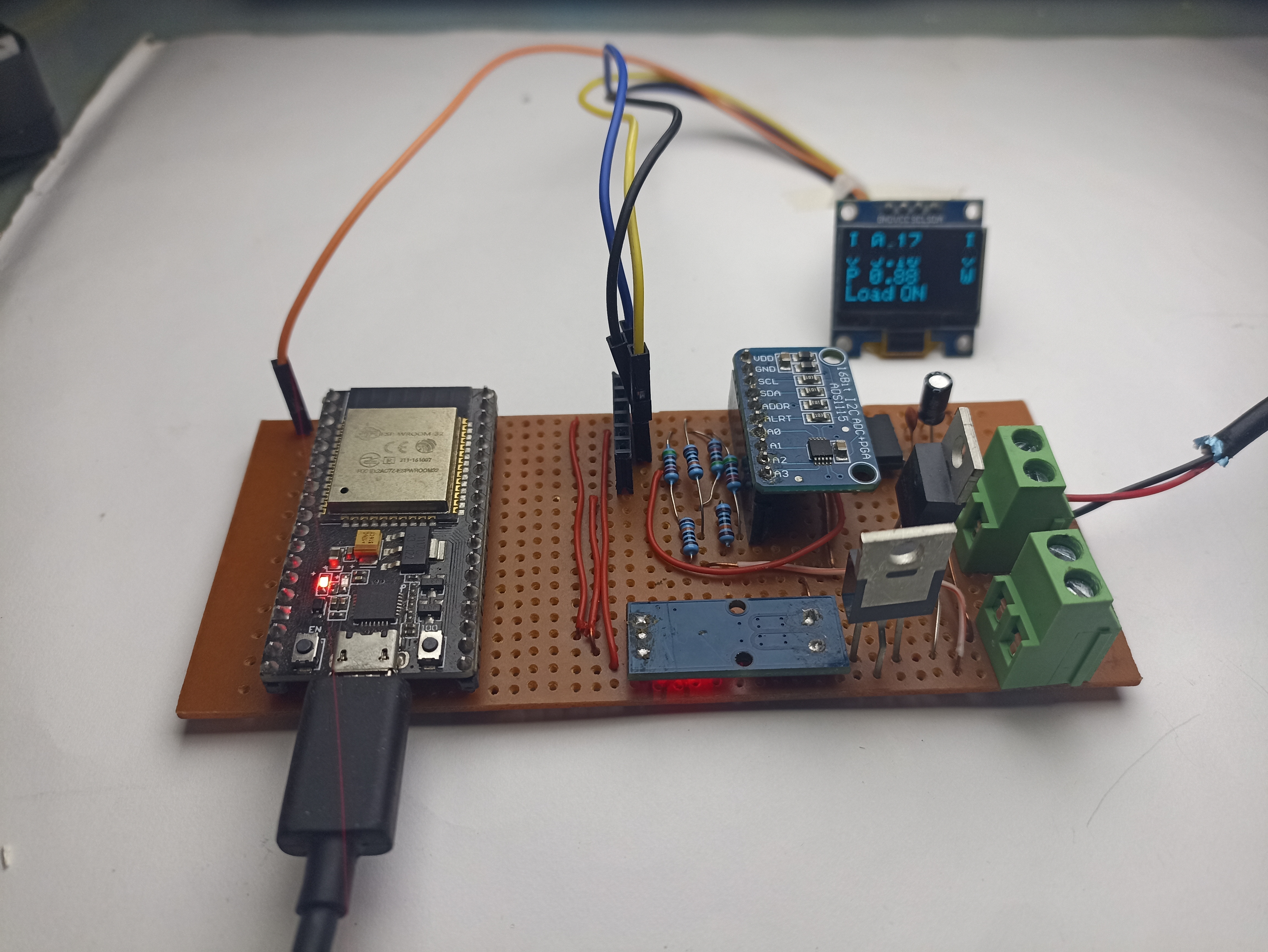
The above picture shows a load of 2ohms being connected to the 5v usb supply , hence we can it has significantly loaded the supply and the voltage breaks down , also the current is compliant with the ohms law and the voltage drop is slightly off from the meter because of several reasons , first the voltage drops at the n channel fets , and my meter not being calibrated and has a zero error , I trust the high resolution adc of this system far more than my meter (also cause my meter has endured significant abuse by passing high currents and multiple fuse blows)
To test the current and power consumption, connect a Load Motor, 12V LED Lights, or anything else at the Load Terminal.
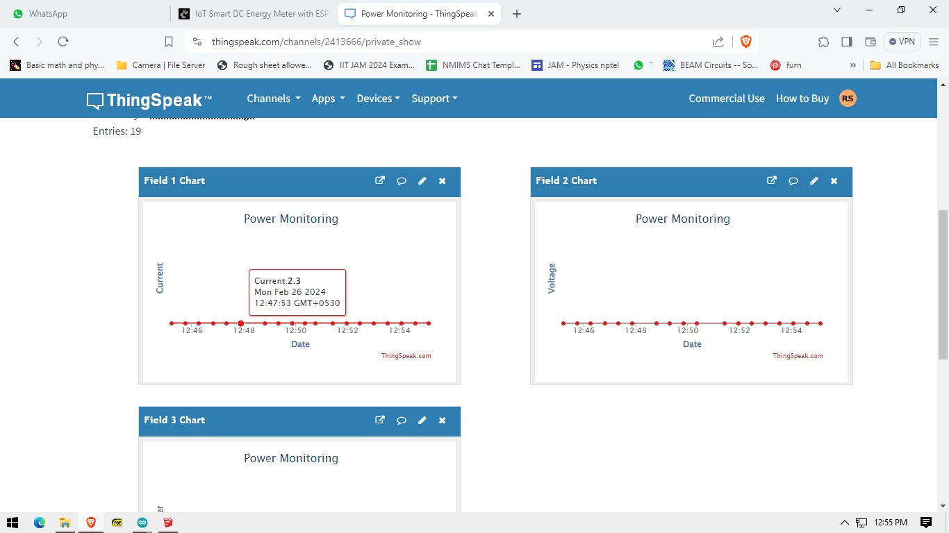
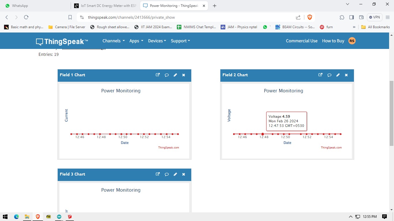
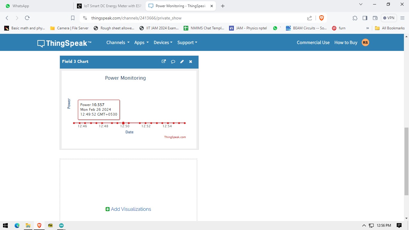
Navigate to the private view of your ThingSpeak Dashboard. You’ll see graphical representations of Battery Voltage, Load Voltage, Current, and Power values over time
Current
Voltage
Power
Testing: Under & Over Voltage Protection System
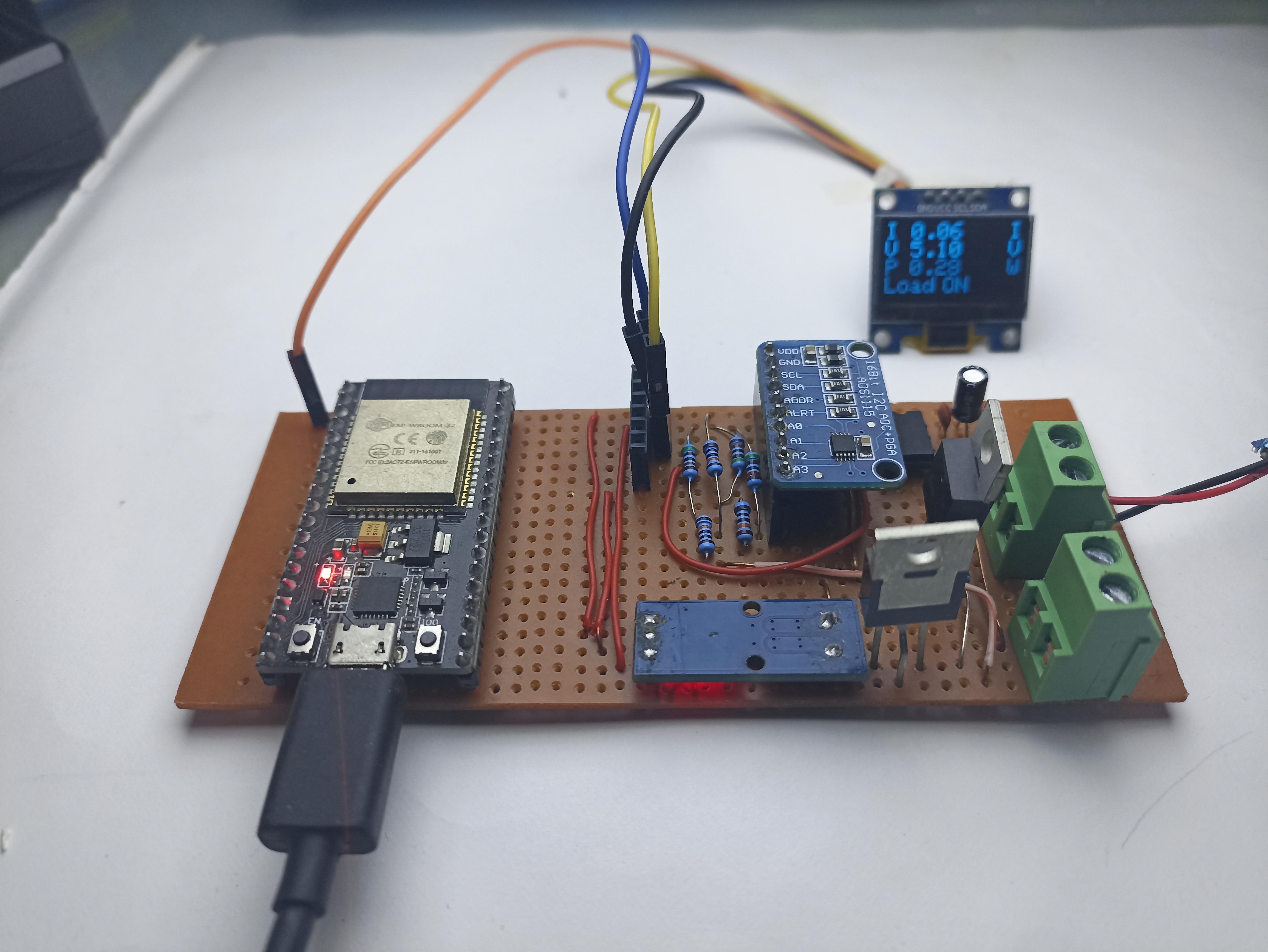
Above you can see the nominal operation of the device, under this condition this it displays load ON , its means everything is okay.
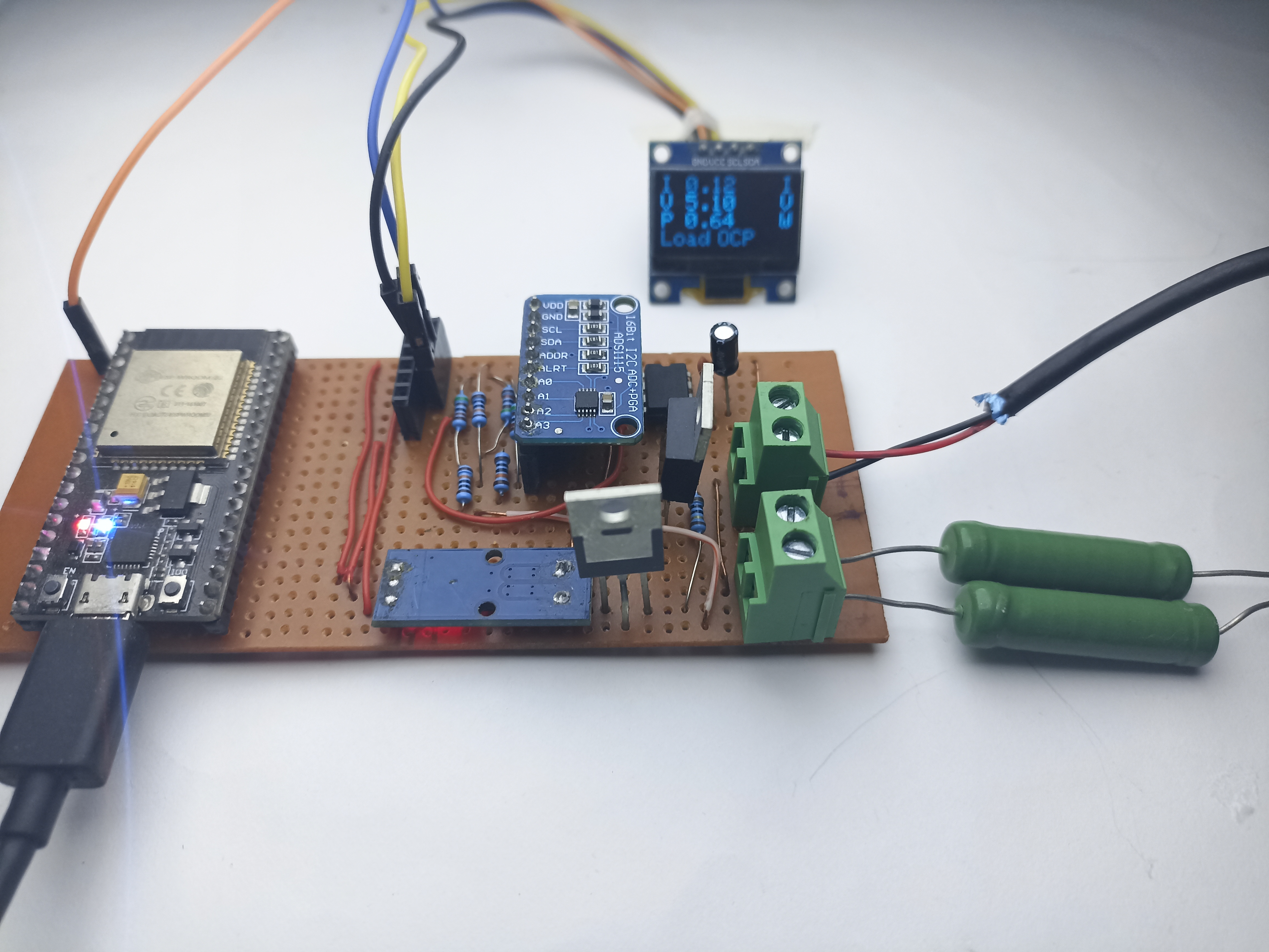
Here you can see the over current protection (termed as OCP) in the display and it can be set via code and here in this demonstration we’ve put a limit of 2A and using a 5V supply and a 2ohm load , the OCP is triggered and the load has been disconnected from the supply and it can also be seen visually by the blue led as the drive voltage is put though gpio2 which is connected to the internal led of the Esp board. Only after a system reset the ocp can be removed.
I really couldn’t show how the over voltage protection or the under voltage protection but I can assure it works within at max 100ms of causing the short , this cannot protect from all shorts or protect from damage due to over voltage or current and it is implemented as a last resort , it is not a software gimmic but it is just not implemented for the aforesaid purpose .
Working Principle
Firstly, we measure the raw voltage from the Hall effect sensor. This voltage is offset by half the supply voltage. So, with zero current, we’ll observe a voltage of half the supply voltage, normally 2.5V (with adjustments for error correction).
Next, we measure the voltage and remove the 2.5V offset. Then, we divide the resulting voltage by a factor of 66mV/A for the 30A version. This factor is specified in the datasheet. Alternatively, you can use a sophisticated library that manages all aspects, including special temperature drift.
Thirdly, I tried to integrate an MC34151P MOSFET driver. This component allows us to pulse-width modulate (PWM) the output, providing control over the power delivered to the load.
The ESP32 continuously monitors the voltage and current of the load, as well as the input voltage. If the voltage falls below or exceeds certain limits, it automatically cuts off the load. Also, it constantly tracks the voltage, current, and power consumption. This data is sent to the cloud every 5 minutes, with the option to adjust the interval as needed.
You can choose not to use the MOSFET driver if you adjust the code to control the gate directly. However, it’s recommended to use a driver to ensure faster switching and prevent the MOSFET from overheating and getting damaged.
Future Scope and Upgrades
- Enhanced Compatibility: Increase current and voltage ratings to support all battery types.
- Improved Current Measurement: Implement advanced methods for more accurate current conversion.
- Dynamic Limits Control: Allow users to adjust voltage and current limits using a rotary encoder for better customization.

