Li-ion batteries are the most popular battery for consumer electronics. Yet, both beginners and experienced Engineers and hobbyists face the problem of choosing proper batteries for their projects. One major issue is manufacturers’ claims about battery capacities usually aren’t accurate.
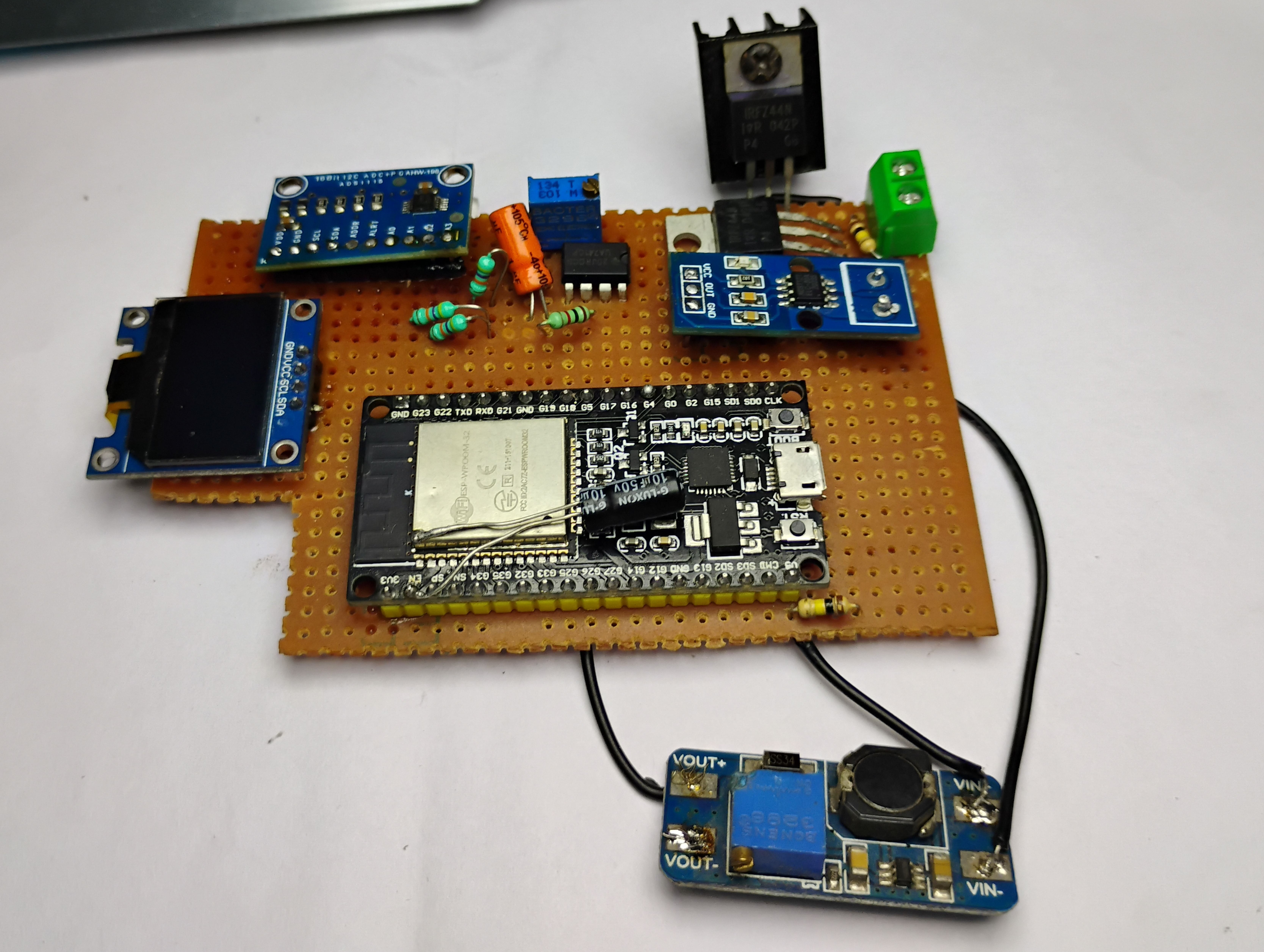
To solve this issue, I built a based on an ESP32 microcontroller board, and we used an N-channel MOSFET to dissipate the electrical energy as heat.
The control algorithm is not a perfect PID (Proportional–integral–derivative) but includes proportional control. we can control the entire device using a webpage hosted on the ESP32 itself, and it also features a 0.96″ OLED display to show multiple parameters in real time.
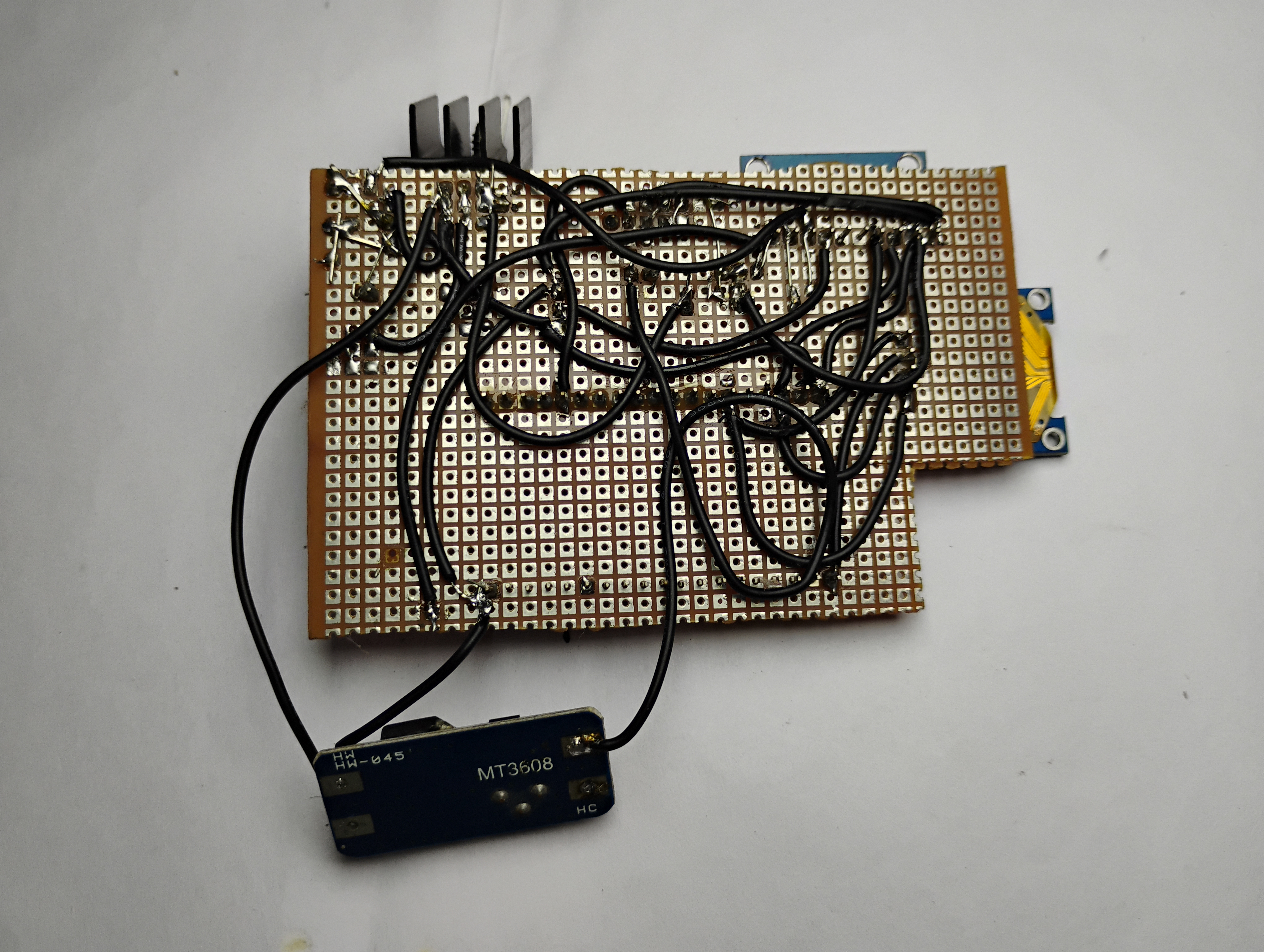
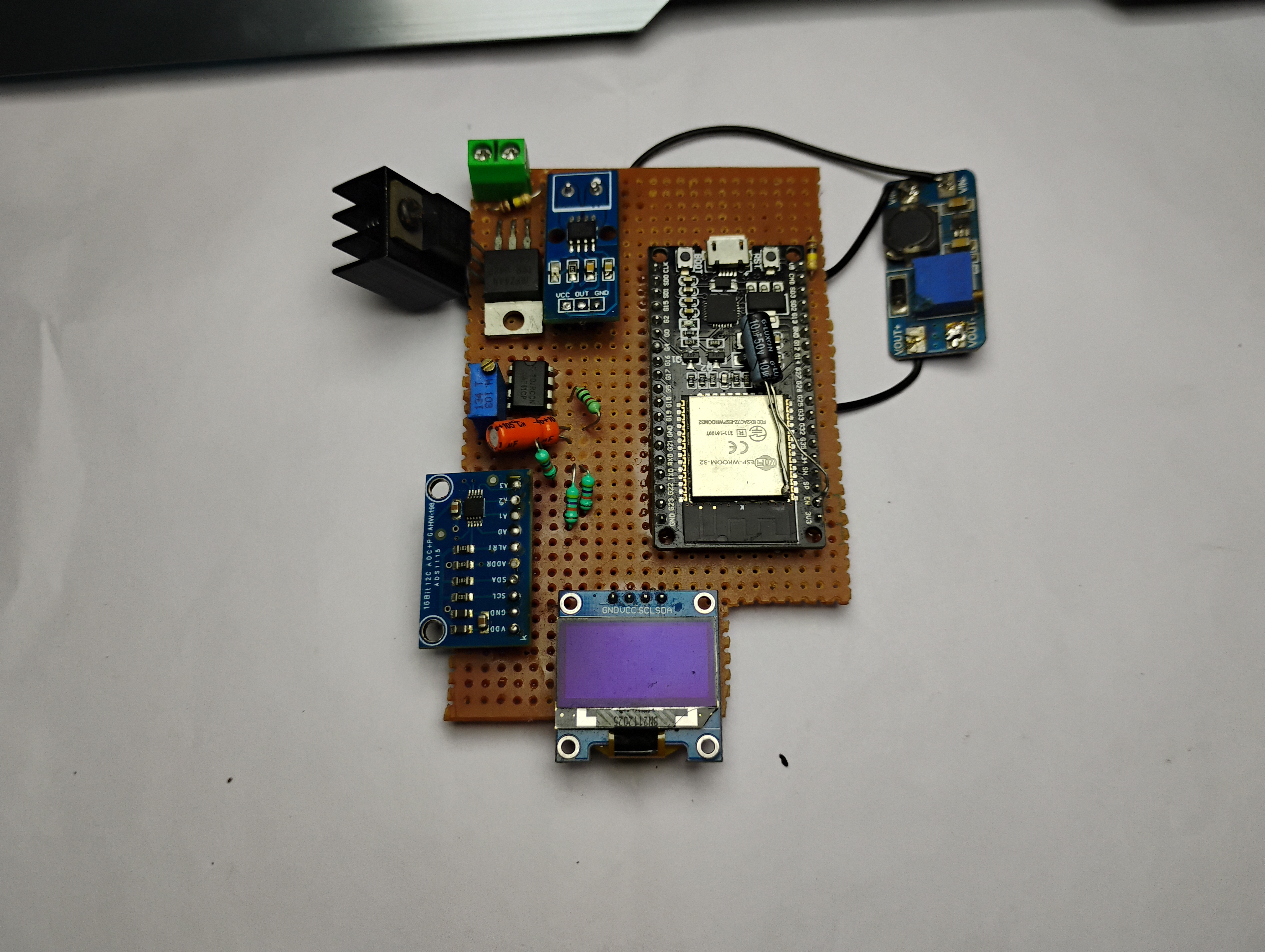
NB: I have showcased two different boards in the post, the main cause is that the first one lacks the boost converter and it was only discovered after I tried to replicate my build, perhaps some of the MOSFETs required have higher threshold voltage than 3.3V and hence the MOSFET never conducts and hence no current flows and eventually the algorithm stops the pwm change and the device doesn’t work
Thank you, PCBWay!

PCBWay is the ultimate choice for prototype PCBs, offering high-quality boards at affordable prices. Sign up using this link for a free coupon or rewards on your first order: PCBWay.
Required Material
- ESP32 Board
- ACS712 Current Sensor
- N-Channel MOSFET
- MOSFET Driver (optional)
- Alternatively, NAND gate or NPN transistors
- 12-bit ADC (if needed)
- Voltage Divider Circuit
- 0.96″ OLED Display
- Passive Components
- Resistors, capacitors, inductors
- PWM Signal Generation Circuit
- ESP32’s PWM output and low-pass filter
- Heat Sink
- Breadboard
- Jumper Wires
- Battery
Specifications
- Measure output voltage and current.
- User-adjustable current regulation
- User-adjustable under-voltage cut-off voltage.
- Real-time time and capacity are shown directly via WebSockets over wifi
- Easy upgradability for higher power models with higher power dissipation.
Features:
- Voltage and Current Monitoring: It can help to monitor up to 12V.
- Overcurrent Protection: this system, can detect overcurrent using a Hall effect sensor, which is polled every 1/10th of a second.
- OLED Display: Displays to show the current state of voltage, current, and time of the start of current.
- User-Defined Cutoff Voltage: The cut-off voltage of the device is user-defined, hence this can be used with different battery chemistries
- High-Resolution ADC: 12-bit ADC is used to sample voltages, and the current from the Hall effect sensor is also sampled using this ADC.
- Current Control: Features feedback from the current sensor to the system, allowing for active current control.
- High Power Dissipation: The device can easily dissipate 55 Watts using the MOSFET with an active cooler. We can increase the current up to 30A, which is the maximum of the current sensor. (For higher currents, it is recommended to use multiple MOSFETs in parallel with balancing resistors.)
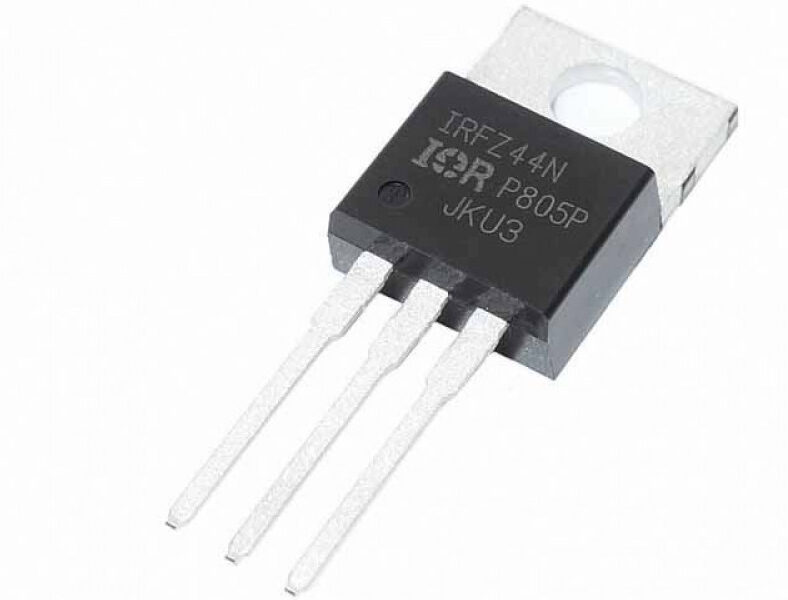
- Reverse Polarity Protection: It features reverse polarity protection using an N-channel MOSFET, which operates in the saturation region and does not require a heatsink.
Theory:
The simplest method to measure current is to plot the voltage vs. the current draws. In real-world scenarios, the battery voltage drops significantly under load, and the current may either decrease (in the case of a resistive load) or increase if the load is designed to draw constant power from the source.
We can use a trick to simplify this process: if we draw a constant 1A current from the battery, we only need to measure the time it can supply that current. The time in hours will instantly give us the battery’s capacity in amp-hours (Ah).
This simplifies our problem: we need a circuit that draws 1A from the battery at all voltage levels. We achieve this using a MOSFET, driving it in the active region (also called the resistive region). In this region, the MOSFET acts as a voltage-controlled current source. By adjusting the gate voltage, we can control the current. Although an ADC is generally required, we can create a PWM signal, pass it through a low-pass filter to produce a voltage, and avoid using the ESP32’s DAC. This method prevents the risk of damaging the ESP32 due to current peaks.
We have effectively created a voltage-controlled current source. Users can skip the MOSFET driver part, as many beginners might not have access to one. Instead, you can use a NAND gate, which is widely available, or build your driver using NPN transistors.
Current measurement –
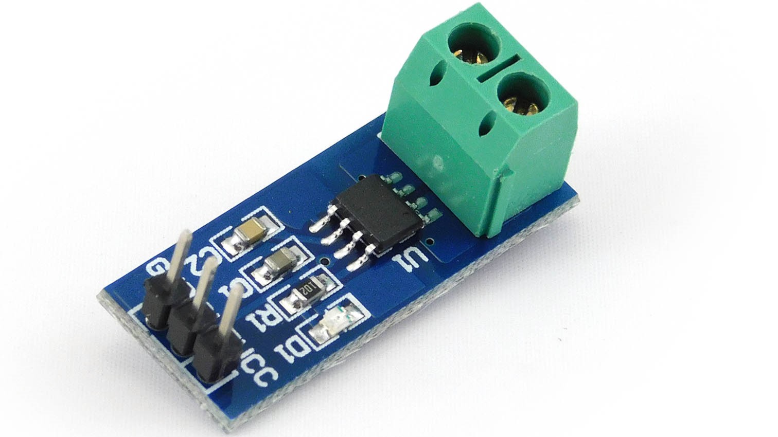
we use the ACS712 Hall effect sensor, which offers advantages over traditional low-value shunt resistors by avoiding voltage drops and providing accurate readings over a wide range of current values.
8
Control MOSFET:
We use feedback to adjust the PWM duty cycle. This PWM signal, filtered to an analog voltage, varies between 0V and 3.3V.
The device uses proportional control, meaning the output changes based on the difference between the input and the set value. Tests show good agreement between the set and experimental results.
Wiring Diagram
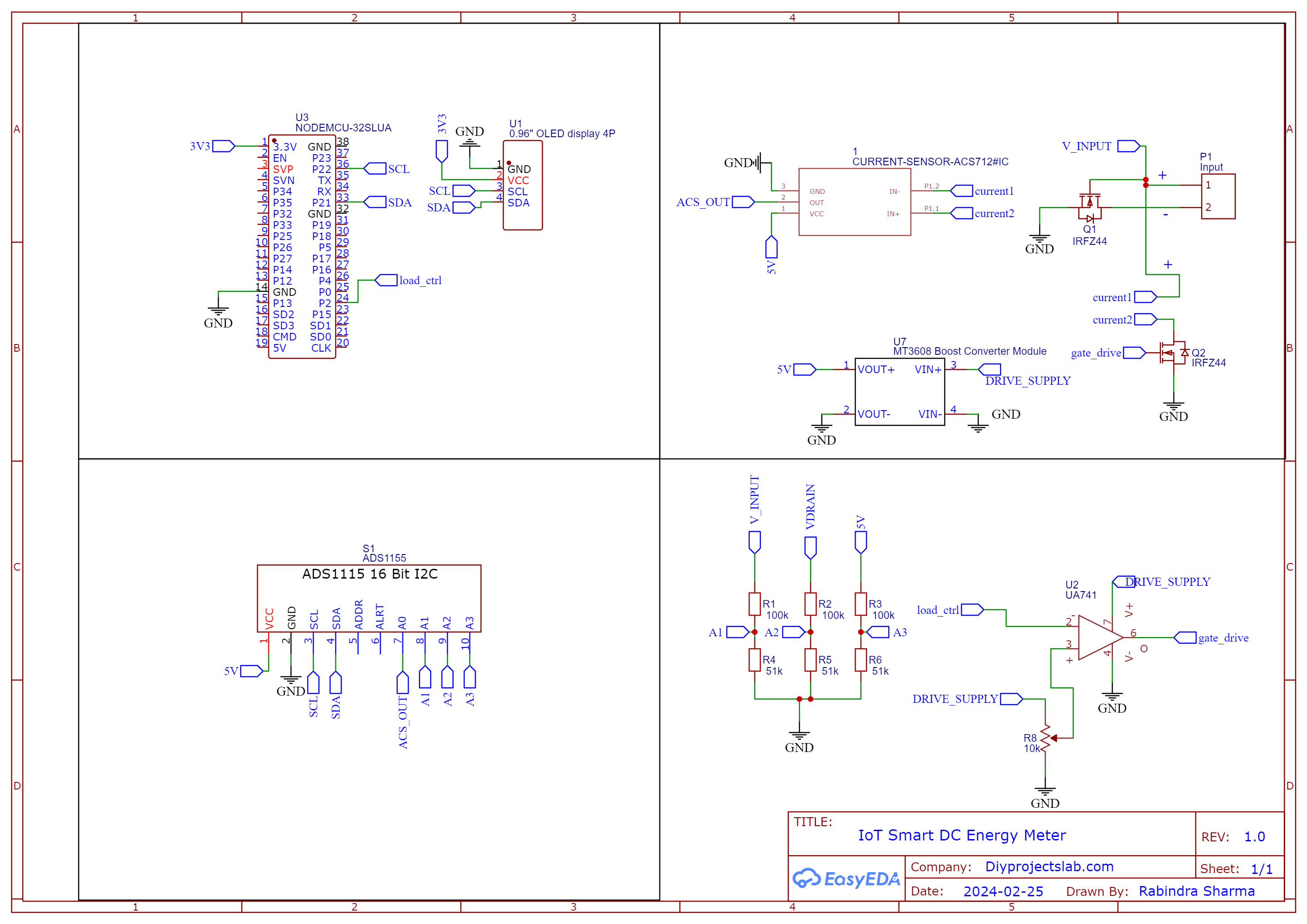
The complete schematic for building an ESP32 battery Capacity Measurement is given below
Build the Circuit!
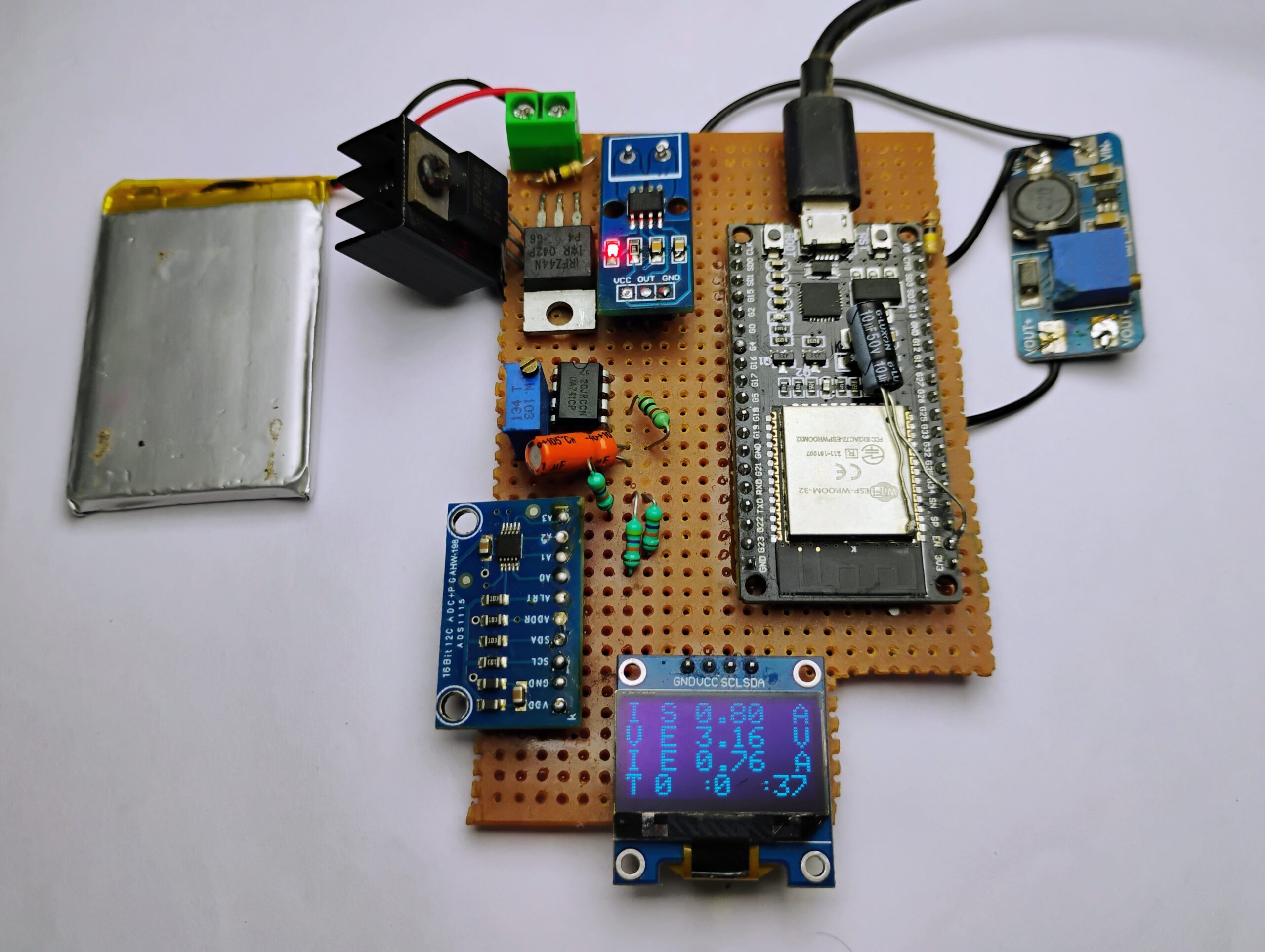
it’s time to solder all the components onto the per-board. Start by placing and soldering the ESP32 board, ADS1115. Next, solder the ACS712 current sensor securely in place. Position and solder the N-channel MOSFET.
[The capacitor in the image soldered to the eps32 is connected from RST to Gnd , some esp32 doesn’t want to boot without pressing the boot button at the startup , so I soldered 10u capacitor so that it boots on its own.]
Source Code
- Download the Code:
- Install Arduino IDE:
- Download and install from Arduino’s website.
- Install Required Libraries:
- Open Arduino IDE, go to
Sketch->Include Library->Manage Libraries.... - Install:
Adafruit GFX,Adafruit SSD1306,ADS1X15.
- Open Arduino IDE, go to
Modify and Upload Code
In lines 61 and 62 of the code, enter your Wi-Fi network’s SSID and password.
|
1 2 |
const char* ssid = "Note 10s"; const char* password = "abcd1234"; |
Upload the Code:
-
- Open the downloaded code file in Arduino IDE.
- Select the ESP32 board from
Tools->Board. - Click the upload button.
|
1 2 3 4 5 6 7 8 9 10 11 12 13 14 15 16 17 18 19 20 21 22 23 24 25 26 27 28 29 30 31 32 33 34 35 36 37 38 39 40 41 42 43 44 45 46 47 48 49 50 51 52 53 54 55 56 57 58 59 60 61 62 63 64 65 66 67 68 69 70 71 72 73 74 75 76 77 78 79 80 81 82 83 84 85 86 87 88 89 90 91 92 93 94 95 96 97 98 99 100 101 102 103 104 105 106 107 108 109 110 111 112 113 114 115 116 117 118 119 120 121 122 123 124 125 126 127 128 129 130 131 132 133 134 135 136 137 138 139 140 141 142 143 144 145 146 147 148 149 150 151 152 153 154 155 156 157 158 159 160 161 162 163 164 165 166 167 168 169 170 171 172 173 174 175 176 177 178 179 180 181 182 183 184 185 186 187 188 189 190 191 192 193 194 195 196 197 198 199 200 201 202 203 204 205 206 207 208 209 210 211 212 213 214 215 216 217 218 219 220 221 222 223 224 225 226 227 228 229 230 231 232 233 234 235 236 237 238 239 240 241 242 243 244 245 246 247 248 249 250 251 252 253 254 255 256 257 258 259 260 261 262 263 264 265 266 267 268 269 270 271 272 273 274 275 276 277 278 279 280 281 282 283 284 285 286 287 288 289 290 291 292 293 294 295 296 297 298 299 300 301 302 303 304 305 306 307 308 309 310 311 312 313 314 315 316 317 318 319 320 321 322 323 324 325 326 327 328 329 330 331 332 333 334 335 336 337 338 339 340 341 342 343 344 345 346 347 348 349 350 351 352 353 354 355 356 357 358 359 360 361 362 363 364 365 366 367 368 369 370 371 372 373 374 375 376 377 378 379 380 381 382 383 384 385 386 387 388 389 390 391 392 393 394 395 396 397 398 399 400 401 402 403 404 405 406 407 408 409 410 411 412 413 414 415 416 417 418 419 420 421 422 423 424 425 426 427 428 429 430 431 432 433 434 435 436 437 438 439 440 441 442 443 444 445 446 447 448 449 450 451 452 453 454 455 456 457 458 459 460 461 462 463 464 465 466 467 468 469 470 471 472 473 474 475 476 |
#include <Arduino.h> #include <WiFi.h> // needed to connect to WiFi #include <WebServer.h> // needed to create a simple web server (make sure tools -> board is set to ESP32, otherwise you will get a "WebServer.h: No such file or directory" error) #include <WebSocketsServer.h> // needed for instant communication between client and server through WebSockets #include <ArduinoJson.h> // needed for JSON encapsulation (send multiple variables with one string) #define LED 2 #include "ADS1X15.h" #include <SPI.h> #include <Wire.h> #include <Adafruit_GFX.h> #include <Adafruit_SSD1306.h> #define SCREEN_WIDTH 128 // OLED display width, in pixels #define SCREEN_HEIGHT 64 // OLED display height, in pixels // Declaration for an SSD1306 display connected to I2C (SDA, SCL pins) // The pins for I2C are defined by the Wire library. // On an arduino UNO: A4(SDA), A5(SCL) // On an arduino MEGA 2560: 20(SDA), 21(SCL) // On an arduino LEONARDO: 2(SDA), 3(SCL), ... #define OLED_RESET -1 // Reset pin # (or -1 if sharing Arduino reset pin) #define SCREEN_ADDRESS 0x3C ///< See datasheet for Address; 0x3D for 128x64, 0x3C for 128x32 #define load_pin 2 Adafruit_SSD1306 display(SCREEN_WIDTH, SCREEN_HEIGHT, &Wire, OLED_RESET); ADS1115 ADS(0x48); float prevails = 0 ; const int freq = 1000; const int ledChannel = 0; const int resolution = 12; //Resolution 8, 10, 12, 15 float set_current = 0; float esp = 0.005; float current_zero_error = -3.16 ; float input_current = 0 ; float input_voltage = 0 ; float drain_voltage = 0 ; float kabs = 50 ; const int maxpwmfreq = (int)(pow(2, resolution) - 1); const int maxpwmfreqss = 2000 ; // experimentally determined int time_lcd = 0 ; int pwmfreq = maxpwmfreq ; void adc_init() { Wire.begin(); ADS.begin(); ADS.setGain(0); // 6.144 volt } const char* ssid = "Note 10s"; const char* password = "abcd1234"; String webpage = "<!DOCTYPE HTML><html> <title>ESP32 Capacity Meter</title><head> <meta name='viewport' content='width=device-width, initial-scale=1'> <link rel='icon' href='data:,'> <style>html { font-family: Arial, Helvetica, sans-serif; display: inline-block; text-align: center;}button { background-color: #04AA6D; /* Green */ border: none; color: white; padding: 20px 50px; text-align: center; text-decoration: none; display: inline-block; font-size: 16px;}h1 { font-size: 1.8rem; color: white;}.topnav { overflow: hidden; background-color: #0A1128;}body { margin: 0;}.content { padding: 50px;}.card-grid { max-width: 1000px; margin: 0 auto; display: grid; grid-gap: 2rem; grid-template-columns: repeat(auto-fit, minmax(200px, 1fr));}.card { background-color: white; box-shadow: 2px 2px 12px 1px rgba(140,140,140,.5);}.card-title { font-size: 1.2rem; font-weight: bold; color: #034078}.reading { font-size: 1.2rem; color: #1282A2;} </style><title>ESP32 Capacity Meter</title><meta name='viewport' content='width=device-width, initial-scale=1'><link rel='icon' href='data:,'></head><body style='background-color: #EEEEEE;'> <div class='topnav'> <h1>ESP32 Battery Capacity Meter</h1> </div> <div class='content'><div class = 'main'> </div> <div class='card-grid'> <div class='card'> <p class='card-title'><i class='fas fa-thermometer-threequarters' style='color:#059e8a;'></i> Voltage</p> <p class='reading'><span id='voltage'>--</span> V</p> </div> <div class='card'> <p class='card-title'> Current</p> <p class='reading'><span id='current'>--</span> A</p> </div> <div class='card'> <p class='card-title'>Power</p> <p class='reading'><span id='power'>--</span> Watt</p> </div><div class='card'> <p class='card-title'>Status</p> <p class='reading'><span id='stats'>Halted</span></p> </div><div class='card'> <p class='card-title'>Time</p> <p class='reading'><span id='time'>--</span> Seconds</p> </div><div class='card'> <p class='card-title'>Capacity</p> <p class='reading'><span id='CAP'>--</span> mAh</p> </div> </div> </div> <div class = 'sclbox'>Set constant current <input type='text' id='constant_current' placeholder='1' /> A</div><br><div class = 'sclbox'>Set constant power <input type='text' id='constant_power' placeholder='4.2' /> W</div><br><div class = 'sclbox'>Set cuttoff voltage <input type='text' id='cuttoff_voltage' placeholder='2.5' /> V</div><br><div class ='Start'><button type='submit' value='Submit' id='CCMODE' >Start CC MODE </button></div><br><div class ='Start'><button type='submit' value='Submit' id='CPMODE' >Start CP MODE </button></div><br><div class ='Start'><button type='submit' value='Submit' id='STOP' >Stop</button></div><br><div class ='Start'><button type='submit' value='Submit' id='cap_mes' >Capacity Mesurnment</button></div></body><script>var Socket;function init() { Socket = new WebSocket('ws://' + window.location.hostname + ':81/'); Socket.onmessage = function(event) { processCommand(event); }; } window.addEventListener('load', onload); document.getElementById('CCMODE').addEventListener('click', CCMODE);document.getElementById('CPMODE').addEventListener('click', CPMODE);document.getElementById('STOP').addEventListener('click',STOP);document.getElementById('cap_mes').addEventListener('click',measure_batt); function CCMODE() { var msg = {mode : 1 ,current: document.getElementById('constant_current').value ,cuttoff_voltage: document.getElementById('cuttoff_voltage').value ,power:0,};console.log(JSON.stringify(msg));Socket.send(JSON.stringify(msg)); } function CPMODE(){ var msg = {mode : 2 ,current:0,cuttoff_voltage: document.getElementById('cuttoff_voltage').value ,power: document.getElementById('constant_power').value ,};console.log(JSON.stringify(msg));Socket.send(JSON.stringify(msg)); } function measure_batt(){ var msg = {mode : 1,current : 1.0 ,cuttoff_voltage: document.getElementById('cuttoff_voltage').value ,};console.log(JSON.stringify(msg));Socket.send(JSON.stringify(msg)); } function STOP(){ var msg = {mode : 0,current:0,cuttoff_voltage:0,power:0,};console.log(JSON.stringify(msg));Socket.send(JSON.stringify(msg)); } function processCommand(event) {var obj = JSON.parse(event.data);var voltage_rf = obj.voltage ; var current_rf = obj.current ;var power_rf = obj.power;var energy = obj.time / (60*60* 1000) ; document.getElementById('voltage').innerHTML = voltage_rf.toFixed(2); document.getElementById('current').innerHTML = current_rf.toFixed(2);document.getElementById('stats').innerHTML = obj.stats;document.getElementById('power').innerHTML = power_rf.toFixed(2);document.getElementById('time').innerHTML = obj.time;document.getElementById('CAP').innerHTML = energy.toFixed(2);console.log(obj.voltage);console.log(obj.current);console.log(obj.stats);console.log(obj.power);console.log(obj.time); } window.onload = function(event) { init(); } </script></html>"; float current_ = 0 ; float cuttoff_voltage_ = 0 ; float power_ = 0 ; float AcsValueF = 0 ; int mode_ = 0 ; unsigned long timee_ = 0 ; unsigned long time_reading = 0 ; bool done_flag = 0 ; //bool final_done_flag = 0 ; int interval = 5000; // send data to the client every 1000ms -> 1s int interval1 = 100; // send data to the client every 100ms -> 0.1s unsigned long previousMillis = 0; // we use the "millis()" command for time reference and this will output an unsigned long unsigned long previousMillis1 = 0; String jsonString = ""; // create a JSON string for sending data to the client StaticJsonDocument<200> doc; // create a JSON container JsonObject object = doc.to<JsonObject>(); WebServer server(80); // the server uses port 80 (standard port for websites WebSocketsServer webSocket = WebSocketsServer(81); // the websocket uses port 81 (standard port for websockets void webSocketEvent(byte num, WStype_t type, uint8_t * payload, size_t length) ; void aux_mode_func() ; void disinit() { if (!display.begin(SSD1306_SWITCHCAPVCC, SCREEN_ADDRESS)) { Serial.println(F("SSD1306 allocation failed")); for (;;) ; // Don't proceed, loop forever } // Show initial display buffer contents on the screen -- //The library initializes this with an Adafruit splash screen. display.clearDisplay(); display.display(); delay(200); // Pause for 2 seconds // Clear the buffer display.clearDisplay(); display.setTextSize(1); // Normal 1:1 pixel scale display.setTextColor(SSD1306_WHITE); display.setCursor(0, 20); display.println(F(" Diyprojectlabs.com")); display.display(); delay(1000); } void disdat( float i_set , int time_sec , float i_exp , float v_exp) { display.clearDisplay(); delay(1); display.setTextSize(2); display.setCursor(0, 0); display.println(F("I S")); display.setCursor(48, 0); display.println(i_set); display.setCursor(115, 0); display.println("A"); display.setCursor(0, 16); display.println(F("V E")); display.setCursor(48, 16); display.println(v_exp); display.setCursor(115, 16); display.println("V"); display.setCursor(0, 32); display.println(F("I E")); display.setCursor(48, 32); display.print((i_exp)); display.setCursor(115, 32); display.println("A"); int mins = time_sec / 60 ; int hours = mins / 60 ; display.setCursor(0, 48); display.println(F("T ")); display.setCursor(20, 48); display.println(hours); //dot display.setCursor(50, 48); display.println(":"); display.setCursor(60, 48); display.println(mins); //dot display.setCursor(90, 48); display.println(":"); display.setCursor(100, 48); display.println(time_sec); display.display(); } void measure() { int16_t raw_data1 = 0; int16_t raw_data2 = 0; int16_t raw_data3 = 0; raw_data1 = ADS.readADC(1); raw_data2 = ADS.readADC(2); raw_data3 = ADS.readADC(3); float vref = (ADS.toVoltage(raw_data3) * 3 )/2; float AcsValue = 0.0, Samples = 0.0, AvgAcs = 0.0, AcsValueF = 0.0; for (int x = 0; x < 11; x++) { //Get 150 samples AcsValue = ADS.readADC(0); //Read current sensor values Samples = Samples + AcsValue; //Add samples together delay (10); // let ADC settle before next sample 3ms } AvgAcs = Samples / 10.0; //Taking Average of Samples //((AvgAcs * (5.0 / 1024.0)) is converitng the read voltage in 0-5 volts //2.5 is offset(I assumed that arduino is working on 5v so the viout at no current comes //out to be 2.5 which is out offset. If your arduino is working on different voltage than //you must change the offset according to the input voltage) //0.066(66mV) is rise in output voltage when 1A current flows at input AcsValueF = (vref - (ADS.toVoltage(AvgAcs) ) ) / 0.066 - current_zero_error ; input_current = AcsValueF ; input_voltage = ADS.toVoltage(raw_data1) * 3 ; drain_voltage = ADS.toVoltage(raw_data2) * 3 ; Serial.println("------------------------------"); Serial.println((input_current), 3); Serial.println("Current drawn (A)"); Serial.println(input_voltage, 3); Serial.println("Input voltage "); Serial.println(drain_voltage, 3); Serial.println("Drain voltage"); Serial.println("------------------------------"); } void mosfetdrive() { int16_t raw_data1 = 0; int16_t raw_data2 = 0; int16_t raw_data3 = 0; raw_data1 = ADS.readADC(1); raw_data2 = ADS.readADC(2); raw_data3 = ADS.readADC(3); float vref = (ADS.toVoltage(raw_data3) * 3 ) / 2; float AcsValue = 0.0, Samples = 0.0, AvgAcs = 0.0, AcsValueF = 0.0; for (int x = 0; x < 11; x++) { //Get 150 samples AcsValue = ADS.readADC(0); //Read current sensor values Samples = Samples + AcsValue; //Add samples together delay (10); // let ADC settle before next sample 3ms } AvgAcs = Samples / 10.0; //Taking Average of Samples //((AvgAcs * (5.0 / 1024.0)) is converitng the read voltage in 0-5 volts //2.5 is offset(I assumed that arduino is working on 5v so the viout at no current comes //out to be 2.5 which is out offset. If your arduino is working on different voltage than //you must change the offset according to the input voltage) //0.066(66mV) is rise in output voltage when 1A current flows at input AcsValueF = (vref - (ADS.toVoltage(AvgAcs) ) ) / 0.066 - current_zero_error ; input_current = AcsValueF ; input_voltage = ADS.toVoltage(raw_data1) * 3 ; // switch places drain_voltage = ADS.toVoltage(raw_data2) * 3 ; Serial.print("Input voltage" + String(input_voltage)); if (mode_ == 1 | mode_ == 2 ) { if (input_voltage < cuttoff_voltage_) { done_flag = 1 ; //final_done_flag =1 ; time_reading = ( millis() - timee_ ) /1000 ; } } Serial.print("Current is " + String(AcsValueF) + "A"); if (mode_ == 2) { set_current = power_ / input_voltage ; } if ( (set_current - AcsValueF) > esp ) { Serial.println("decreasing"); pwmfreq = (pwmfreq - kabs * abs(set_current - AcsValueF) ); if(pwmfreq >= maxpwmfreq) { pwmfreq = maxpwmfreq ; } ledcWrite(ledChannel, (int)abs(pwmfreq) ); } if ( (set_current - AcsValueF) < esp ) { Serial.println("incremnet"); pwmfreq = (pwmfreq + kabs * abs(set_current - AcsValueF)); if(pwmfreq <= 10) { pwmfreq = 10 ; } ledcWrite(ledChannel, (int)abs(pwmfreq)); } Serial.println("The pwm is " + String(pwmfreq)); } void setup() { pinMode(LED, OUTPUT); adc_init(); disinit(); disdat(0,0,0,0); ledcSetup(ledChannel, freq, resolution); // attach the channel to the GPIO2 to be controlled ledcAttachPin(LED, ledChannel); ledcWrite(ledChannel, maxpwmfreq); delay(500); //digitalWrite(mgate, HIGH); Serial.begin(115200); // init serial port for debugging WiFi.begin(ssid, password); // start WiFi interface Serial.println("Establishing connection to WiFi with SSID: " + String(ssid)); // print SSID to the serial interface for debugging while (WiFi.status() != WL_CONNECTED) { // wait until WiFi is connected delay(1000); Serial.print("."); } Serial.print("Connected to network with IP address: "); Serial.println(WiFi.localIP()); // show IP address that the ESP32 has received from router server.on("/", []() { // define here wat the webserver needs to do server.send(200, "text/html", webpage); // -> it needs to send out the HTML string "webpage" to the client }); server.begin(); // start server webSocket.begin(); // start websocket webSocket.onEvent(webSocketEvent); // define a callback function -> what does the ESP32 need to do when an event from the websocket is received? -> run function "webSocketEvent() } void loop() { //Serial.print("mode+doneflag" + String(mode_) + " " +String(done_flag)); server.handleClient(); // Needed for the webserver to handle all clients webSocket.loop(); // Update function for the webSockets unsigned long now = millis(); // read out the current "time" ("millis()" gives the time in ms since the Arduino started) if (mode_ != 0 && done_flag == 0 ) { if ((now - previousMillis1) > interval1) { // check if "interval" ms has passed since last time the clients were updated mosfetdrive(); //Serial.println("-----------------mosfet driver --------------------"); previousMillis1 = now ; } } //Serial.println("1st loop state" + String(now - previousMillis) ); if ((now - previousMillis) > interval) { // check if "interval" ms has passed since last time the clients were updated disdat(set_current,time_lcd,input_current,input_voltage); // create a JSON Object object["voltage"] = input_voltage; // write data into the JSON object -> I used "rand1" and "rand2" here, but you can use anything else object["current"] = input_current ; // write data into the JSON object -> I used "rand1" and "rand2" here, but you can use anything else if (mode_ == 0) { object["stats"] = "Stopped"; } if(mode_ == 0 && done_flag == 1 ){ object["stats"] = "Stopped"; } if (mode_ == 1) { object["stats"] = "CC Mode"; //timee_ = millis(); } if (mode_ == 2) { object["stats"] = "CP Mode"; //timee_ = millis(); } if(mode_ == 0 & done_flag== 1 ){ object["stats"] = "Done."; } object["power"] = input_current * input_voltage ; // write data into the JSON object -> I used "rand1" and "rand2" here, but you can use anything else //Serial.println("The time passe is " + String((long)( millis() - timee_ ) /3600000 ) ); if(done_flag == 0 && mode_ == 0 ){ object["time"] = 0; time_lcd = 0 ; } if( done_flag ==1 && mode_ == 0 ){ object["time"] = time_reading ; time_lcd = time_reading ; } if(mode_!=0 && done_flag == 0 ){ int temp = (int)( millis() - timee_) / 1000 ; object["time"] = temp; time_reading = temp; time_lcd = temp ; } serializeJson(doc, jsonString); // convert JSON object to string Serial.println(jsonString); // print JSON string to console for debug purposes (you can comment this out) webSocket.broadcastTXT(jsonString); // send JSON string to clients previousMillis = now; // reset previousMillis } if(done_flag == 1 ){ mode_ = 0 ; aux_mode_func(); } } void webSocketEvent(byte num, WStype_t type, uint8_t * payload, size_t length) { // the parameters of this callback function are always the same -> num: id of the client who send the event, type: type of message, payload: actual data sent and length: length of payload switch (type) { // switch on the type of information sent case WStype_DISCONNECTED: // if a client is disconnected, then type == WStype_DISCONNECTED Serial.println("Client " + String(num) + " disconnected"); break; case WStype_CONNECTED: // if a client is connected, then type == WStype_CONNECTED Serial.println("Client " + String(num) + " connected"); // optionally you can add code here what to do when connected break; case WStype_TEXT: // if a client has sent data, then type == WStype_TEXT // try to decipher the JSON string received StaticJsonDocument<200> doc; // create a JSON container DeserializationError error = deserializeJson(doc, payload); if (error) { Serial.print(F("deserializeJson() failed: ")); Serial.println(error.f_str()); return; } else { // JSON string was received correctly, so information can be retrieved: cuttoff_voltage_ = doc["cuttoff_voltage"]; set_current = doc["current"]; mode_ = doc["mode"]; power_ = doc["power"]; if (mode_ == 1 ) { timee_ = millis(); ledcWrite(ledChannel, maxpwmfreq); done_flag = 0 ; } if (mode_ == 0 ) { time_reading = ( millis() - timee_ ) /1000 ; ledcWrite(ledChannel, maxpwmfreq); done_flag = 1; } if (mode_ == 2 ) { timee_ = millis(); ledcWrite(ledChannel, maxpwmfreq); done_flag = 0 ; } } Serial.println("Data received from the user "); Serial.println("mode : " + String(mode_)); Serial.println("current limit : " + String(current_)); Serial.println("mode : " + String(mode_)); Serial.println("power : " + String(power_)); break; } Serial.println(""); } void aux_mode_func(){ ledcWrite(ledChannel, maxpwmfreq); } |
Success
After uploading the code, power the ESP32, and you will see the data displayed on OLED.
Working
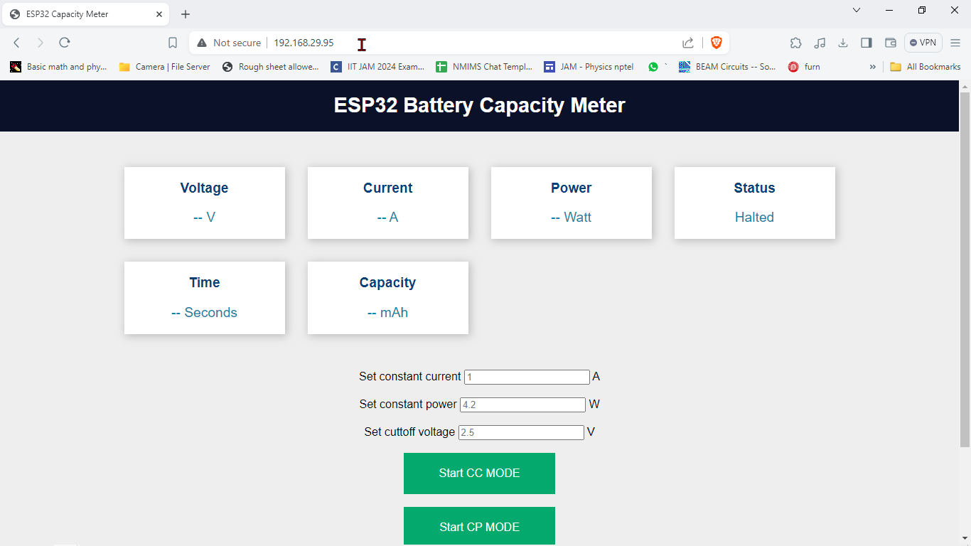
After uploading the code, open the Serial Monitor. The ESP32 local IP address will be displayed there. Enter this IP address into your web browser and press Enter, This will open the webpage hosted by the ESP32.
So, in my case, the IP Address of ESP32 is 192.168.29.95.
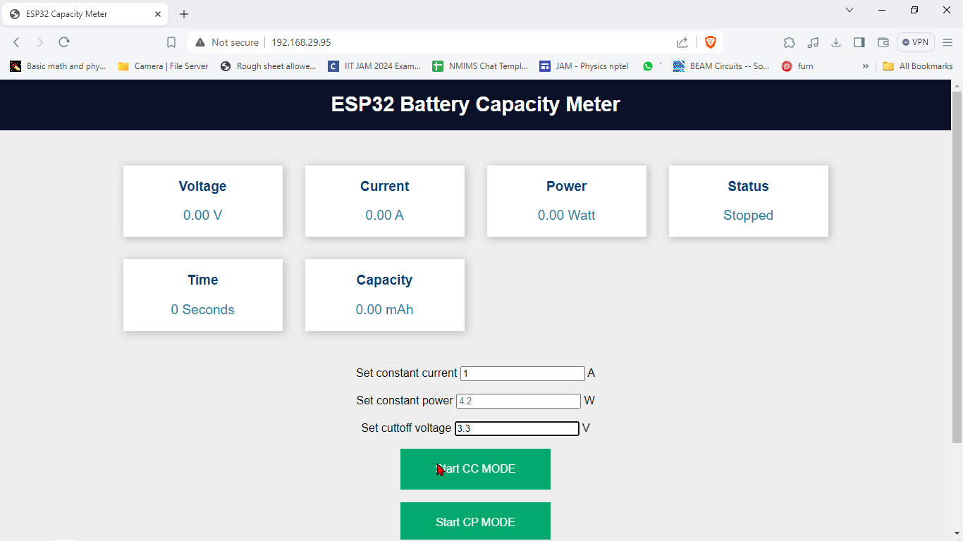
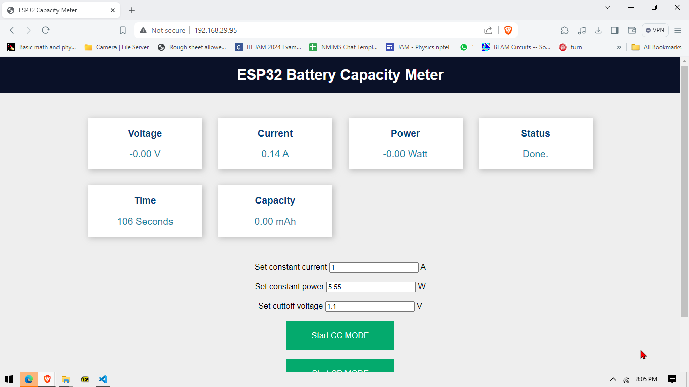
After logging the IP address into the browser we are greeted with a control panel , let me guide you with the salient features of the panel
- The below the title shows the voltage , current and power values. (Note: you need to upto 5 seconds for these value are updated !)
- Also the status are shown , it can be one of the
- Started : indicating the test has begun
- Halted : indicating the test hasn’t begun or stopped by the user
- Done : indicating that the test has stopped
- Time : shows the time in seconds after the test has started
- In addition there are 3 test boxes which are used in combination of the buttons on green color .
- The are various modes in which this device can be used
- Constant Current Mode (CC Mode) : this mode as the name suggest is used to use this device as a constant current load. You just need to specify the cutoff voltage and the constant current in the first field. and click on start button , the test would start and when the battery voltage lowers below the cuttoff voltage the test stops.
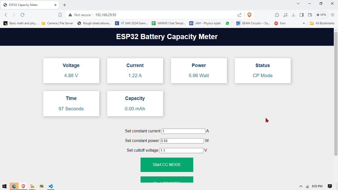
- Constant Power Mode (CP Mode): in this mode the device does it best to draw the designated current as set by the user , you need to specify the cutoff voltage and the constant power and click on the Cp mode to start the test.
In both the tests the test stops when either the user stops it using the button provided or when the voltage falls below a certain cutoff voltage given by the user - Battery Capacity : in this mode as the name suggest you need to just specify the cutoff voltage of the cell , when you want to stop the measurement. The test will end and using the time it took to completely discharge the capacity of the battery can be calculate.
- Misc uses : the following device can be used as a standalone constant current load, you just need to set the cutoff voltage to 0 or some low value that your power supply would never reaach under operating conditions and give the desired current and Click on CC Mode . And similar can be said for the constant power mode.
The above image depicts the screen first presented after logging to the IP address of the esp32
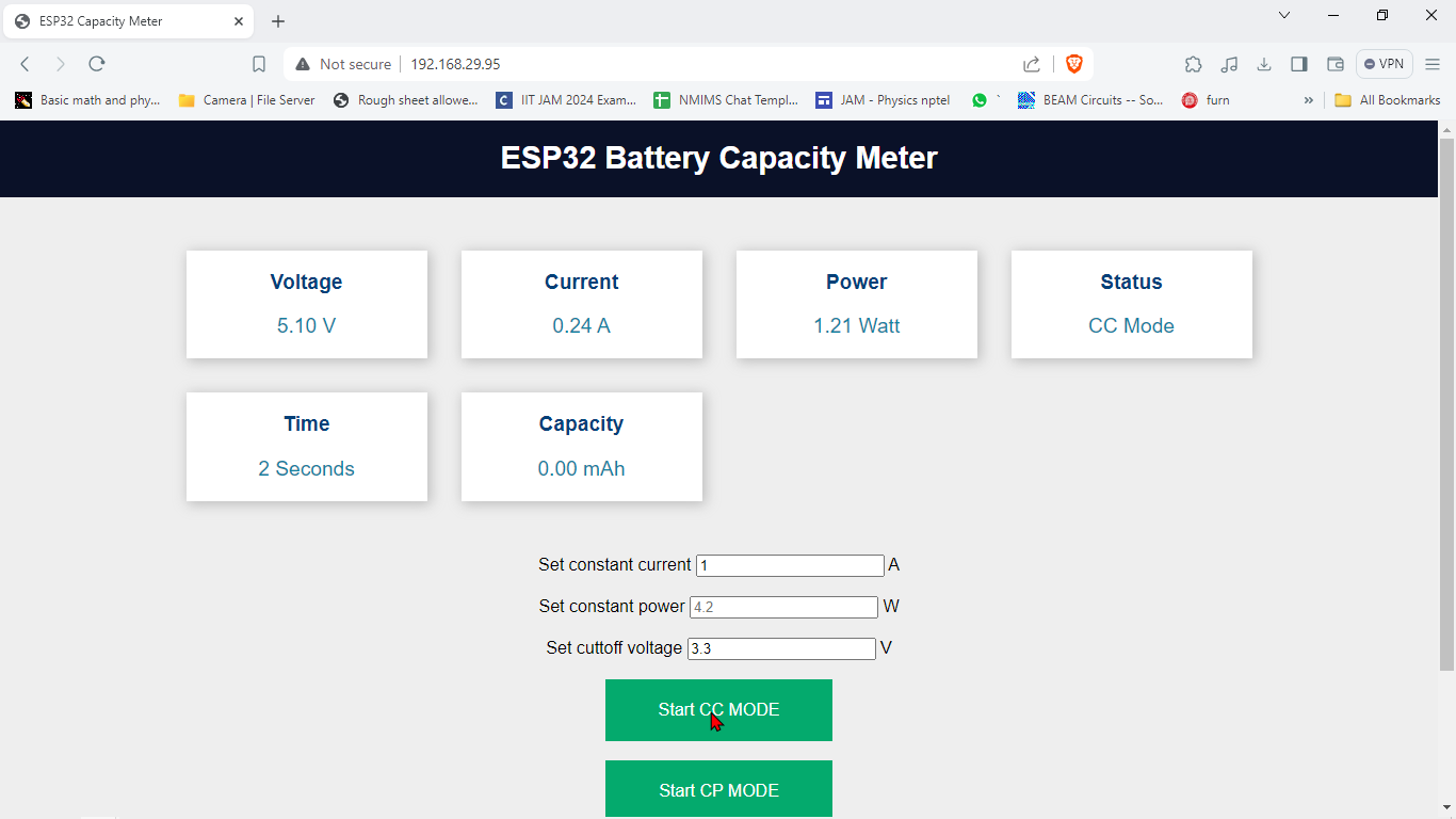
The above image shows the CC mode and minimum parameters to be filled to use it correctly
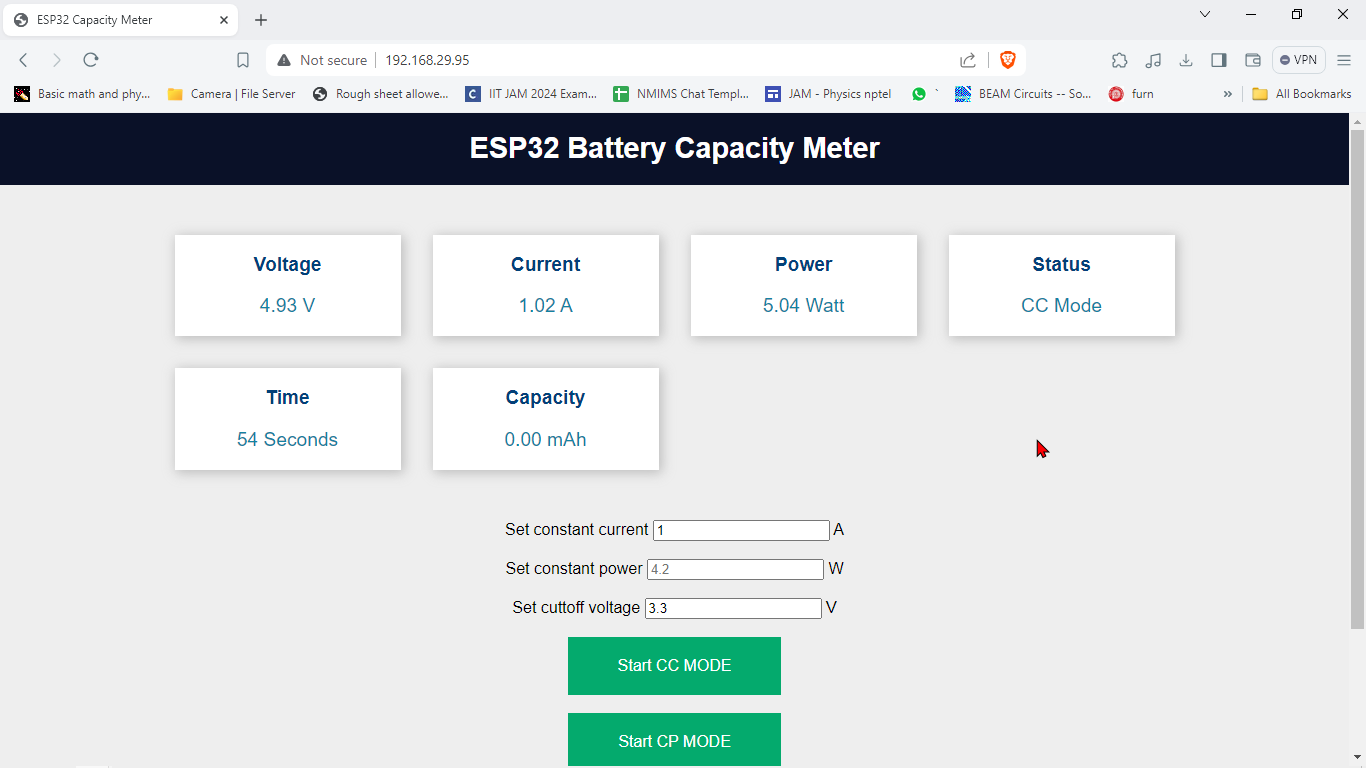
The above image shows the CC Mode running and various parameters being updated in the control panel
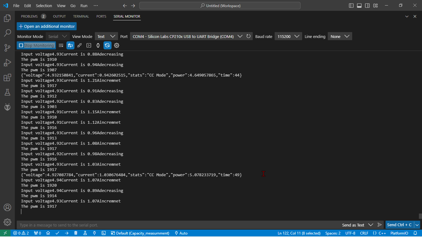
Data being exchanged in Json and the pwm change as the system tried to stabilize its current as per the user entered value
The Above image shows the relation between the set current and experimental current as the system tries to make both same.
The above image shows that when the system ends the test when the voltage falls below the cutoff voltage.
The above image shows constant power mode , the system tries to maintain the power draw to 5.55W and we can see that it indeed is very close , it takes time to settle the power
Scope and Future Work
While the project methods might suggest a flawless system, several known software issues exist despite careful bug avoidance.
- Battery Disconnection Issue: If the battery is disconnected mid-test and reconnected shortly afterward, it can cause a short circuit. Therefore, it’s always advisable to use a fuse in series with the battery whenever possible and the battery should be disconnected or changed only when the test has been stopped! .
- Capacity Measurement Accuracy: Sometimes, capacity measurements are not accurate. Although capacity and power calculations have been tested, the current meter has intrinsic errors. The control algorithm doesn’t work well at lower current values (~100mA – 400mA), making the system unsuitable for low-current measurements.
- Constant Current Load Usage: To use the device as a constant current load, you need to set the cutoff voltage lower than the input supply voltage. Additionally, you must restart the device every time you change the load. If the load changes or gets disconnected, the control algorithm puts the device into saturation, requiring a restart.
These issues are mainly software-related, and all constructive criticism is welcomed to improve the system further. You can mail me regarding issues at rabindrasharmaas188@gmail.com

