Introduction
This post will introduce the ESP32 UWB (Ultra-Wideband) board, which uses the same technology as Apple’s AirTag. It’s a powerful device for accurate location tracking of objects or people. Today, I’m learning about this board and its UWB technology, and we might try to copy Apple’s AirTag features! Let’s start by doing our first project with the ESP32 UWB board using the Arduino IDE. I purchased the boards from Makerfabs.com for $43.
Ultra-wideband (UWB) technology has been around for a while, but it’s recently gained attention as popular smartphones, like the iPhone 11 and Samsung Note 20 Ultra, started using it. UWB is essential because it offers new wireless communication and location-tracking opportunities. Check out the previous post, Exploring the Revolutionary RYUW122 UWB Module for Precision Indoor Positioning.
What is Ultra-Wideband (UWB)?
Ultra-wideband (UWB) is a wireless communication technology that works differently than standard radio systems like WiFi or Bluetooth. In most radio systems, information is transmitted by changing a continuous sine wave signal. This could involve changing the amplitude (signal strength), frequency (number of waves per second), or phase (timing of the wave). UWB, however, uses short, rapid pulses instead of continuous waves.
How Does UWB Work?
UWB sends out very short pulses of radio energy, usually just a couple of nanoseconds separated. This means the system doesn’t rely on a sine wave to carry information but uses bursts of energy that are harder to detect and much lower in power. Because of this, UWB can operate without a license as it stays below a specific power threshold, meaning it won’t interfere with other RF systems.
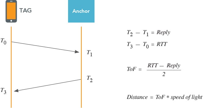
UWB measures the time it takes for a radio signal to travel from one device to another, which is called TAG and ANCHOR. This time is known as the time of flight (TOF). The distance between the two devices is calculated using the following formula:
UWB measures the time a radio signal travels between two devices, known as the TAG and the ANCHOR. This time is known as the Time of Flight (ToF). The distance between the two devices is calculated using the following formula:
Distance = (Time × Speed of Light) / 2
- Time: The round-trip time of the signal.
- Speed of Light: Approximately 3×10⁸ m/s

There are three main ways UWB can be used depending on the needs of the application:
- Time Difference of Arrival (TDoA)
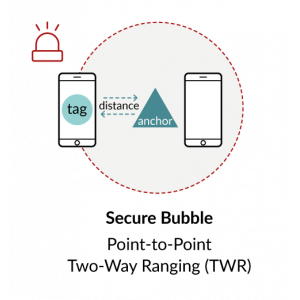
- Two-Way Ranging (TWR)
- Phase Difference of Arrival (PDoA)
| Method | Description | Advantages | Disadvantages | Target Applications |
|---|---|---|---|---|
| 1. Time Difference of Arrival (TDoA) | It uses synchronized anchors to receive signals from mobile devices, calculating position through time differences. |
|
|
|
| 2. Two-Way Ranging (TWR) | Measures round trip time between two devices to calculate distance, enabling 2D/3D location through triangulation. |
|
|
|
| 3. Phase Difference of Arrival (PDoA) | Combines TWR with bearing measurement for relative positioning without extra infrastructure. |
|
|
|
DW3000 UWB Transceivers Chip
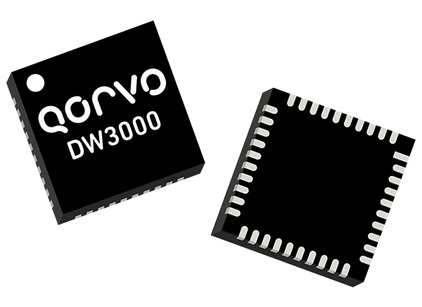
The DW3000 chip, developed by Qorvo, is used in ultra-wideband (UWB) wireless technology for accurate indoor positioning and location-based services. It is perfect for applications like asset tracking, industrial automation, and robotics, using time-of-flight (ToF) to measure distances between devices.
DW3000 Key Features:
- Interoperable with Apple U1 & U2 chips
- Supports UWB channels 5 (6.5 GHz) and 9 (8 GHz)
- Optimized for low-power battery operation
- Compliant with IEEE 802.15.4-2015 and 802.15.4z standards
- Programmable transmitter output power and coherent receiver for accuracy
- Data rates of 850 kbps, 6.8 Mbps
Applications:
- High-accuracy real-time location systems
- Real-time location systems (RTLS) using two-way ranging or TDoA
- Location-aware wireless sensor networks (WSNs)
- Asset tracking
- Factory/warehouse automation & security
- Healthcare staff & patient location
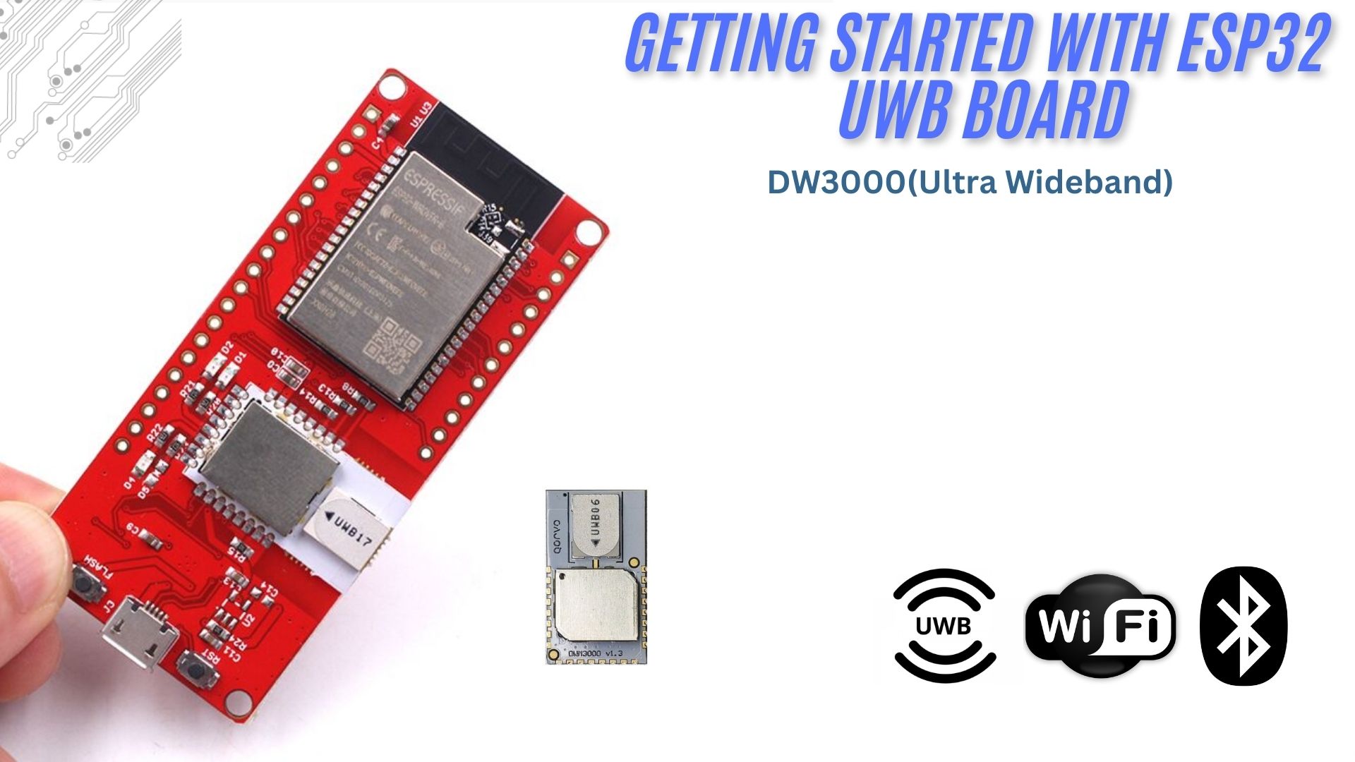
ESP32 DW3000 UWB(Ultra Wideband) Board
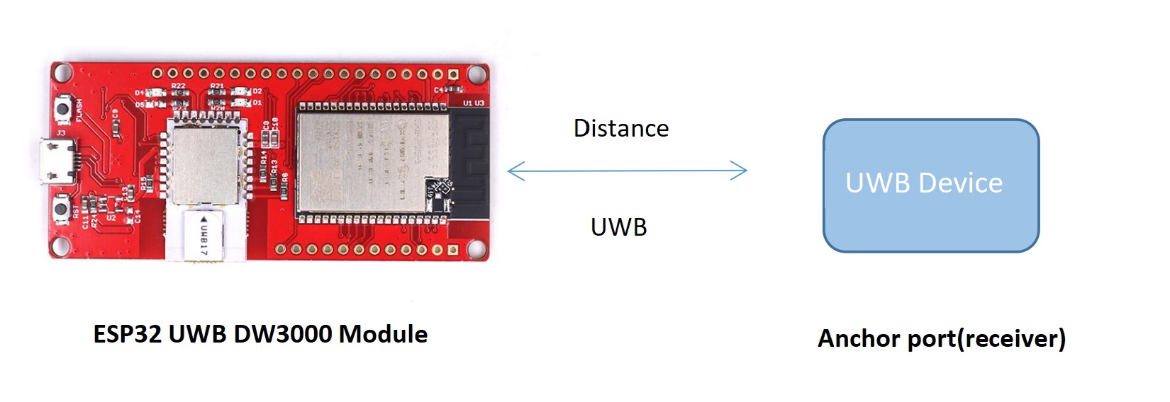
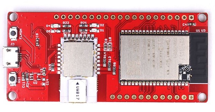
The ESP32 UWB module integrates the Decawave DW3000 chip and ESP32 WiWiFiodule, manufactured by Makerfabs. Ultra-wideband (UWB) is a short-range wireless communication protocol using radio waves. It works like a radar, continuously scanning and locking onto another device (Anchor) to calculate its location. It’s also compatible with Apple’s U1 chip, allowing it to work within the Apple ecosystem. It enables secure, reliable ranging, and precise sensing, providing spatial context for wireless devices.
The Front Side contains the ESP32 WROOM/Wrover and DW3000 modules, along with two push buttons (flash and reset) and a micro-USB port for firmware uploads and serial communication.
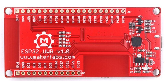
Back Side: Contains the CP2102 chip for UART communication, with labeled input/output ports.
Features:
- Decawave DWM3000: Provides precise location tracking.
- ESP32: Enables fast and robust applications.
- It supports WiWiFind Bluetooth for seamless wireless connectivity.
- Arduino Compatible: Easily programmable with Arduino.
- Micro-USB Connector: For power and data transfer.
- Power Supply: Operates with a USB voltage range of 4.8V to 5.5V (5.0V typical).
Setting up ESP32 UWB in Arduino IDE
To use the DW3000 with ESP32 on Arduino IDE, you’ll need the DW3000 library. This library lets you work with Decawave’s DW3000 chips/modules on any microcontroller.
Install ESP32 Board Package
- Go to Preferences in Arduino IDE, and add the ESP32 board package URL.
Enter the following into the “Additional Board Manager URL” field:
|
1 |
https://raw.githubusercontent.com/espressif/arduino-esp32/gh-pages/package_esp32_index.json |
- After adding the URL, install the ESP32 package from Tools > Board Manager.
Install DW3000 Library
Developed initially by NConcepts, the library is available on Makerfabs’ GitHub.
The library helps with message transmission, and timestamp handling (for ranging and location sensing), and supports various operation modes of the DW3000. It simplifies the otherwise complex configuration of the DW3000 for easy use.
Example Code For ESP32 UWB Sender and Receiver
For Transmitter:
- Copy the transmitter code below and open it in Arduino IDE.
- Select the correct board (
ESP32-Wroom-DA-Module) and port from theToolsmenu. - Upload the code to the ESP32, which acts as the transmitter.
|
1 2 3 4 5 6 7 8 9 10 11 12 13 14 15 16 17 18 19 20 21 22 23 24 25 26 27 28 29 30 31 32 33 34 35 36 37 38 39 40 41 42 43 44 45 46 47 48 49 50 51 52 53 54 55 56 57 58 59 60 61 62 63 64 65 66 67 68 69 70 71 72 73 74 75 76 77 78 79 80 81 82 83 84 85 86 87 88 89 90 91 92 93 94 95 96 97 98 99 100 101 102 103 104 105 106 107 108 109 110 111 112 113 114 115 116 117 118 119 120 121 122 123 124 125 126 127 128 129 130 131 132 133 134 135 136 137 138 139 140 141 142 143 144 145 146 147 148 149 150 151 152 153 154 155 156 157 158 159 160 |
#include "dw3000.h" #define APP_NAME "SIMPLE TX v1.1" // connection pins const uint8_t PIN_RST = 27; // reset pin const uint8_t PIN_IRQ = 34; // irq pin const uint8_t PIN_SS = 4; // spi select pin /* Default communication configuration. We use default non-STS DW mode. */ static dwt_config_t config = { 5, /* Channel number. */ DWT_PLEN_128, /* Preamble length. Used in TX only. */ DWT_PAC8, /* Preamble acquisition chunk size. Used in RX only. */ 9, /* TX preamble code. Used in TX only. */ 9, /* RX preamble code. Used in RX only. */ 1, /* 0 to use standard 8 symbol SFD, 1 to use non-standard 8 symbol, 2 for non-standard 16 symbol SFD and 3 for 4z 8 symbol SDF type */ DWT_BR_6M8, /* Data rate. */ DWT_PHRMODE_STD, /* PHY header mode. */ DWT_PHRRATE_STD, /* PHY header rate. */ (129 + 8 - 8), /* SFD timeout (preamble length + 1 + SFD length - PAC size). Used in RX only. */ DWT_STS_MODE_OFF, DWT_STS_LEN_64, /* STS length, see allowed values in Enum dwt_sts_lengths_e */ DWT_PDOA_M0 /* PDOA mode off */ }; /* The frame sent in this example is an 802.15.4e standard blink. It is a 12-byte frame composed of the following fields: * - byte 0: frame type (0xC5 for a blink). * - byte 1: sequence number, incremented for each new frame. * - byte 2 -> 9: device ID, see NOTE 1 below. */ static uint8_t tx_msg[] = {0xC5, 0, 'D', 'E', 'C', 'A', 'W', 'A', 'V', 'E'}; /* Index to access to sequence number of the blink frame in the tx_msg array. */ #define BLINK_FRAME_SN_IDX 1 #define FRAME_LENGTH (sizeof(tx_msg) + FCS_LEN) // The real length that is going to be transmitted /* Inter-frame delay period, in milliseconds. */ #define TX_DELAY_MS 500 extern dwt_txconfig_t txconfig_options; void setup() { UART_init(); test_run_info((unsigned char *)APP_NAME); /* Configure SPI rate, DW3000 supports up to 38 MHz */ /* Reset DW IC */ spiBegin(PIN_IRQ, PIN_RST); spiSelect(PIN_SS); delay(200); // Time needed for DW3000 to start up (transition from INIT_RC to IDLE_RC, or could wait for SPIRDY event) while (!dwt_checkidlerc()) // Need to make sure DW IC is in IDLE_RC before proceeding { test_run_info((unsigned char *)"IDLE FAILED01\r\n"); while (100) ; } dwt_softreset(); delay(200); while (!dwt_checkidlerc()) // Need to make sure DW IC is in IDLE_RC before proceeding { test_run_info((unsigned char *)"IDLE FAILED02\r\n"); while (100) ; } // test_run_info((unsigned char *)"IDLE OK\r\n"); if (dwt_initialise(DWT_DW_INIT) == DWT_ERROR) { test_run_info((unsigned char *)"INIT FAILED\r\n"); while (100) ; } // test_run_info((unsigned char *)"INIT OK\r\n"); // Enabling LEDs here for debug so that for each TX the D1 LED will flash on DW3000 red eval-shield boards. dwt_setleds(DWT_LEDS_ENABLE | DWT_LEDS_INIT_BLINK); // Configure DW IC. See NOTE 5 below. if (dwt_configure(&config)) // if the dwt_configure returns DWT_ERROR either the PLL or RX calibration has failed the host should reset the device { test_run_info((unsigned char *)"CONFIG FAILED\r\n"); while (100) ; } // test_run_info((unsigned char *)"CONFIG OK\r\n"); /* Configure the TX spectrum parameters (power PG delay and PG Count) */ dwt_configuretxrf(&txconfig_options); } void loop() { /* Write frame data to DW IC and prepare transmission. See NOTE 3 below.*/ dwt_writetxdata(FRAME_LENGTH - FCS_LEN, tx_msg, 0); /* Zero offset in TX buffer. */ /* In this example since the length of the transmitted frame does not change, * nor the other parameters of the dwt_writetxfctrl function, the * dwt_writetxfctrl call could be outside the main while(1) loop. */ dwt_writetxfctrl(FRAME_LENGTH, 0, 0); /* Zero offset in TX buffer, no ranging. */ /* Start transmission. */ dwt_starttx(DWT_START_TX_IMMEDIATE); delay(10); // Sleep(TX_DELAY_MS); /* Poll DW IC until TX frame sent event set. See NOTE 4 below. * STATUS register is 4 bytes long but, as the event we are looking at is in the first byte of the register, we can use this simplest API * function to access it.*/ while (!(dwt_read32bitreg(SYS_STATUS_ID) & SYS_STATUS_TXFRS_BIT_MASK)) { test_run_info((unsigned char *)"WHAT!!!\r\n"); /* Reads and validate device ID returns DWT_ERROR if it does not match expected else DWT_SUCCESS */ // if (dwt_check_dev_id() == DWT_SUCCESS) { // UART_puts((char *)"DEV ID OK"); } // else { // UART_puts((char *)"DEV ID FAILED"); } // delay(500); // dwt_write32bitreg(SYS_STATUS_ID, SYS_STATUS_TXFRS_BIT_MASK); // delay(1000); }; /* Clear TX frame sent event. */ dwt_write32bitreg(SYS_STATUS_ID, SYS_STATUS_TXFRS_BIT_MASK); test_run_info((unsigned char *)"TX Frame Sent"); /* Execute a delay between transmissions. */ Sleep(TX_DELAY_MS); /* Increment the blink frame sequence number (modulo 256). */ tx_msg[BLINK_FRAME_SN_IDX]++; } /***************************************************************************************************************************************************** * NOTES: * * 1. The device ID is a hard coded constant in the blink to keep the example simple but for a real product every device should have a unique ID. * For development purposes it is possible to generate a DW IC unique ID by combining the Lot ID & Part Number values programmed into the * DW IC during its manufacture. However there is no guarantee this will not conflict with someone else�s implementation. We recommended that * customers buy a block of addresses from the IEEE Registration Authority for their production items. See "EUI" in the DW IC User Manual. * 2. In a real application, for optimum performance within regulatory limits, it may be necessary to set TX pulse bandwidth and TX power, (using * the dwt_configuretxrf API call) to per device calibrated values saved in the target system or the DW IC OTP memory. * 3. dwt_writetxdata() takes the full size of tx_msg as a parameter but only copies (size - 2) bytes as the check-sum at the end of the frame is * automatically appended by the DW IC. This means that our tx_msg could be two bytes shorter without losing any data (but the sizeof would not * work anymore then as we would still have to indicate the full length of the frame to dwt_writetxdata()). * 4. We use polled mode of operation here to keep the example as simple as possible, but the TXFRS status event can be used to generate an interrupt. * Please refer to DW IC User Manual for more details on "interrupts". * 5. Desired configuration by user may be different to the current programmed configuration. dwt_configure is called to set desired * configuration. ****************************************************************************************************************************************************/ |
For Receiver
- Open the provided receiver code in a new Arduino IDE window.
- Select the same board (
ESP32-Wroom-DA-Module)and port for the receiver. - Upload this code to the ESP32 and act as the receiver.
|
1 2 3 4 5 6 7 8 9 10 11 12 13 14 15 16 17 18 19 20 21 22 23 24 25 26 27 28 29 30 31 32 33 34 35 36 37 38 39 40 41 42 43 44 45 46 47 48 49 50 51 52 53 54 55 56 57 58 59 60 61 62 63 64 65 66 67 68 69 70 71 72 73 74 75 76 77 78 79 80 81 82 83 84 85 86 87 88 89 90 91 92 93 94 95 96 97 98 99 100 101 102 103 104 105 106 107 108 109 110 111 112 113 114 115 116 117 118 119 120 121 122 123 124 125 |
#include "dw3000.h" #define APP_NAME "SIMPLE RX v1.1" // connection pins const uint8_t PIN_RST = 27; // reset pin const uint8_t PIN_IRQ = 34; // irq pin const uint8_t PIN_SS = 4; // spi select pin /* Default communication configuration. We use default non-STS DW mode. */ static dwt_config_t config = { 5, /* Channel number. */ DWT_PLEN_128, /* Preamble length. Used in TX only. */ DWT_PAC8, /* Preamble acquisition chunk size. Used in RX only. */ 9, /* TX preamble code. Used in TX only. */ 9, /* RX preamble code. Used in RX only. */ 1, /* 0 to use standard 8 symbol SFD, 1 to use non-standard 8 symbol, 2 for non-standard 16 symbol SFD and 3 for 4z 8 symbol SDF type */ DWT_BR_6M8, /* Data rate. */ DWT_PHRMODE_STD, /* PHY header mode. */ DWT_PHRRATE_STD, /* PHY header rate. */ (129 + 8 - 8), /* SFD timeout (preamble length + 1 + SFD length - PAC size). Used in RX only. */ DWT_STS_MODE_OFF, /* STS disabled */ DWT_STS_LEN_64, /* STS length see allowed values in Enum dwt_sts_lengths_e */ DWT_PDOA_M0 /* PDOA mode off */ }; /* Buffer to store received frame. See NOTE 1 below. */ static uint8_t rx_buffer[FRAME_LEN_MAX]; /* Hold copy of status register state here for reference so that it can be examined at a debug breakpoint. */ uint32_t status_reg; /* Hold copy of frame length of frame received (if good) so that it can be examined at a debug breakpoint. */ uint16_t frame_len; void setup() { UART_init(); test_run_info((unsigned char *)APP_NAME); /* Configure SPI rate, DW3000 supports up to 38 MHz */ /* Reset DW IC */ spiBegin(PIN_IRQ, PIN_RST); spiSelect(PIN_SS); delay(200); // Time needed for DW3000 to start up (transition from INIT_RC to IDLE_RC, or could wait for SPIRDY event) while (!dwt_checkidlerc()) // Need to make sure DW IC is in IDLE_RC before proceeding { UART_puts("IDLE FAILED\r\n"); while (1) ; } dwt_softreset(); delay(200); if (dwt_initialise(DWT_DW_INIT) == DWT_ERROR) { UART_puts("INIT FAILED\r\n"); while (1) ; } // Enabling LEDs here for debug so that for each TX the D1 LED will flash on DW3000 red eval-shield boards. dwt_setleds(DWT_LEDS_ENABLE | DWT_LEDS_INIT_BLINK); // Configure DW IC. See NOTE 5 below. if (dwt_configure(&config)) // if the dwt_configure returns DWT_ERROR either the PLL or RX calibration has failed the host should reset the device { UART_puts("CONFIG FAILED\r\n"); while (1) ; } } void loop() { /* TESTING BREAKPOINT LOCATION #1 */ /* Clear local RX buffer to avoid having leftovers from previous receptions This is not necessary but is included here to aid reading * the RX buffer. * This is a good place to put a breakpoint. Here (after first time through the loop) the local status register will be set for last event * and if a good receive has happened the data buffer will have the data in it, and frame_len will be set to the length of the RX frame. */ memset(rx_buffer, 0, sizeof(rx_buffer)); /* Activate reception immediately. See NOTE 2 below. */ dwt_rxenable(DWT_START_RX_IMMEDIATE); /* Poll until a frame is properly received or an error/timeout occurs. See NOTE 3 below. * STATUS register is 5 bytes long but, as the event we are looking at is in the first byte of the register, we can use this simplest API * function to access it. */ while (!((status_reg = dwt_read32bitreg(SYS_STATUS_ID)) & (SYS_STATUS_RXFCG_BIT_MASK | SYS_STATUS_ALL_RX_ERR))) { }; if (status_reg & SYS_STATUS_RXFCG_BIT_MASK) { /* A frame has been received, copy it to our local buffer. */ frame_len = dwt_read32bitreg(RX_FINFO_ID) & RX_FINFO_RXFLEN_BIT_MASK; if (frame_len <= FRAME_LEN_MAX) { dwt_readrxdata(rx_buffer, frame_len - FCS_LEN, 0); /* No need to read the FCS/CRC. */ } /* Clear good RX frame event in the DW IC status register. */ dwt_write32bitreg(SYS_STATUS_ID, SYS_STATUS_RXFCG_BIT_MASK); test_run_info((unsigned char *)"Frame Received"); } else { /* Clear RX error events in the DW IC status register. */ dwt_write32bitreg(SYS_STATUS_ID, SYS_STATUS_ALL_RX_ERR); } } /***************************************************************************************************************************************************** * NOTES: * * 1. In this example, maximum frame length is set to 127 bytes which is 802.15.4 UWB standard maximum frame length. DW IC supports an extended * frame length (up to 1023 bytes long) mode which is not used in this example. * 2. Manual reception activation is performed here but DW IC offers several features that can be used to handle more complex scenarios or to * optimise system's overall performance (e.g. timeout after a given time, automatic re-enabling of reception in case of errors, etc.). * 3. We use polled mode of operation here to keep the example as simple as possible, but RXFCG and error/timeout status events can be used to generate * interrupts. Please refer to DW IC User Manual for more details on "interrupts". ****************************************************************************************************************************************************/ |
Once you can upload the sender code to one ESP32 UWB board and the receiver code to another, Upu will see the data on the Serial Monitor.
upon testingFor Transmitter:
The transmitter sends a simple 802.15.4e standard blink frame (a 12-byte message).
- You will see a message on the Serial Monitor:
"TX Frame Sent"Each time a frame is successfully transmitted.
|
1 2 3 4 5 |
SIMPLE TX v1.1 TX Frame Sent TX Frame Sent TX Frame Sent ... |
For Receiver:
The receiver waits for incoming frames. When a valid frame is received:
- It will display a message,
"Frame Received", along with the frame data.
|
1 2 3 4 5 |
SIMPLE RX v1.1 Frame Received Frame Received Frame Received ... |
How to Use the ESP32 UWB DW3000 Module to Measure Distance from Anchor Point
RX code
Copy the RX code below and paste it into the Arduino IDE.
|
1 2 3 4 5 6 7 8 9 10 11 12 13 14 15 16 17 18 19 20 21 22 23 24 25 26 27 28 29 30 31 32 33 34 35 36 37 38 39 40 41 42 43 44 45 46 47 48 49 50 51 52 53 54 55 56 57 58 59 60 61 62 63 64 65 66 67 68 69 70 71 72 73 74 75 76 77 78 79 80 81 82 83 84 85 86 87 88 89 90 91 92 93 94 95 96 97 98 99 100 101 102 103 104 105 106 107 108 109 110 111 112 113 114 115 116 117 118 119 120 121 122 123 124 125 126 127 128 129 130 131 132 133 134 135 136 137 138 139 140 141 142 143 144 145 146 147 148 149 150 151 152 153 154 155 156 157 158 159 160 161 162 163 164 165 166 167 168 169 170 171 172 |
#include "dw3000.h" #define PIN_RST 27 #define PIN_IRQ 34 #define PIN_SS 4 #define RNG_DELAY_MS 1000 #define TX_ANT_DLY 16385 #define RX_ANT_DLY 16385 #define ALL_MSG_COMMON_LEN 10 #define ALL_MSG_SN_IDX 2 #define RESP_MSG_POLL_RX_TS_IDX 10 #define RESP_MSG_RESP_TX_TS_IDX 14 #define RESP_MSG_TS_LEN 4 #define POLL_TX_TO_RESP_RX_DLY_UUS 240 #define RESP_RX_TIMEOUT_UUS 400 /* Default communication configuration. We use default non-STS DW mode. */ static dwt_config_t config = { 5, /* Channel number. */ DWT_PLEN_128, /* Preamble length. Used in TX only. */ DWT_PAC8, /* Preamble acquisition chunk size. Used in RX only. */ 9, /* TX preamble code. Used in TX only. */ 9, /* RX preamble code. Used in RX only. */ 1, /* 0 to use standard 8 symbol SFD, 1 to use non-standard 8 symbol, 2 for non-standard 16 symbol SFD and 3 for 4z 8 symbol SDF type */ DWT_BR_6M8, /* Data rate. */ DWT_PHRMODE_STD, /* PHY header mode. */ DWT_PHRRATE_STD, /* PHY header rate. */ (129 + 8 - 8), /* SFD timeout (preamble length + 1 + SFD length - PAC size). Used in RX only. */ DWT_STS_MODE_OFF, /* STS disabled */ DWT_STS_LEN_64, /* STS length see allowed values in Enum dwt_sts_lengths_e */ DWT_PDOA_M0 /* PDOA mode off */ }; static uint8_t tx_poll_msg[] = {0x41, 0x88, 0, 0xCA, 0xDE, 'W', 'A', 'V', 'E', 0xE0, 0, 0}; static uint8_t rx_resp_msg[] = {0x41, 0x88, 0, 0xCA, 0xDE, 'V', 'E', 'W', 'A', 0xE1, 0, 0, 0, 0, 0, 0, 0, 0, 0, 0}; static uint8_t frame_seq_nb = 0; static uint8_t rx_buffer[20]; static uint32_t status_reg = 0; static double tof; static double distance; extern dwt_txconfig_t txconfig_options; void setup() { UART_init(); spiBegin(PIN_IRQ, PIN_RST); spiSelect(PIN_SS); delay(2); // Time needed for DW3000 to start up (transition from INIT_RC to IDLE_RC, or could wait for SPIRDY event) while (!dwt_checkidlerc()) // Need to make sure DW IC is in IDLE_RC before proceeding { UART_puts("IDLE FAILED\r\n"); while (1) ; } if (dwt_initialise(DWT_DW_INIT) == DWT_ERROR) { UART_puts("INIT FAILED\r\n"); while (1) ; } // Enabling LEDs here for debug so that for each TX the D1 LED will flash on DW3000 red eval-shield boards. dwt_setleds(DWT_LEDS_ENABLE | DWT_LEDS_INIT_BLINK); /* Configure DW IC. See NOTE 6 below. */ if (dwt_configure(&config)) // if the dwt_configure returns DWT_ERROR either the PLL or RX calibration has failed the host should reset the device { UART_puts("CONFIG FAILED\r\n"); while (1) ; } /* Configure the TX spectrum parameters (power, PG delay and PG count) */ dwt_configuretxrf(&txconfig_options); /* Apply default antenna delay value. See NOTE 2 below. */ dwt_setrxantennadelay(RX_ANT_DLY); dwt_settxantennadelay(TX_ANT_DLY); /* Set expected response's delay and timeout. See NOTE 1 and 5 below. * As this example only handles one incoming frame with always the same delay and timeout, those values can be set here once for all. */ dwt_setrxaftertxdelay(POLL_TX_TO_RESP_RX_DLY_UUS); dwt_setrxtimeout(RESP_RX_TIMEOUT_UUS); /* Next can enable TX/RX states output on GPIOs 5 and 6 to help debug, and also TX/RX LEDs * Note, in real low power applications the LEDs should not be used. */ dwt_setlnapamode(DWT_LNA_ENABLE | DWT_PA_ENABLE); Serial.println("Range RX"); Serial.println("Setup over........"); } void loop() { /* Write frame data to DW IC and prepare transmission. See NOTE 7 below. */ tx_poll_msg[ALL_MSG_SN_IDX] = frame_seq_nb; dwt_write32bitreg(SYS_STATUS_ID, SYS_STATUS_TXFRS_BIT_MASK); dwt_writetxdata(sizeof(tx_poll_msg), tx_poll_msg, 0); /* Zero offset in TX buffer. */ dwt_writetxfctrl(sizeof(tx_poll_msg), 0, 1); /* Zero offset in TX buffer, ranging. */ /* Start transmission, indicating that a response is expected so that reception is enabled automatically after the frame is sent and the delay * set by dwt_setrxaftertxdelay() has elapsed. */ dwt_starttx(DWT_START_TX_IMMEDIATE | DWT_RESPONSE_EXPECTED); /* We assume that the transmission is achieved correctly, poll for reception of a frame or error/timeout. See NOTE 8 below. */ while (!((status_reg = dwt_read32bitreg(SYS_STATUS_ID)) & (SYS_STATUS_RXFCG_BIT_MASK | SYS_STATUS_ALL_RX_TO | SYS_STATUS_ALL_RX_ERR))) { }; /* Increment frame sequence number after transmission of the poll message (modulo 256). */ frame_seq_nb++; if (status_reg & SYS_STATUS_RXFCG_BIT_MASK) { uint32_t frame_len; /* Clear good RX frame event in the DW IC status register. */ dwt_write32bitreg(SYS_STATUS_ID, SYS_STATUS_RXFCG_BIT_MASK); /* A frame has been received, read it into the local buffer. */ frame_len = dwt_read32bitreg(RX_FINFO_ID) & RXFLEN_MASK; if (frame_len <= sizeof(rx_buffer)) { dwt_readrxdata(rx_buffer, frame_len, 0); /* Check that the frame is the expected response from the companion "SS TWR responder" example. * As the sequence number field of the frame is not relevant, it is cleared to simplify the validation of the frame. */ rx_buffer[ALL_MSG_SN_IDX] = 0; if (memcmp(rx_buffer, rx_resp_msg, ALL_MSG_COMMON_LEN) == 0) { uint32_t poll_tx_ts, resp_rx_ts, poll_rx_ts, resp_tx_ts; int32_t rtd_init, rtd_resp; float clockOffsetRatio; /* Retrieve poll transmission and response reception timestamps. See NOTE 9 below. */ poll_tx_ts = dwt_readtxtimestamplo32(); resp_rx_ts = dwt_readrxtimestamplo32(); /* Read carrier integrator value and calculate clock offset ratio. See NOTE 11 below. */ clockOffsetRatio = ((float)dwt_readclockoffset()) / (uint32_t)(1 << 26); /* Get timestamps embedded in response message. */ resp_msg_get_ts(&rx_buffer[RESP_MSG_POLL_RX_TS_IDX], &poll_rx_ts); resp_msg_get_ts(&rx_buffer[RESP_MSG_RESP_TX_TS_IDX], &resp_tx_ts); /* Compute time of flight and distance, using clock offset ratio to correct for differing local and remote clock rates */ rtd_init = resp_rx_ts - poll_tx_ts; rtd_resp = resp_tx_ts - poll_rx_ts; tof = ((rtd_init - rtd_resp * (1 - clockOffsetRatio)) / 2.0) * DWT_TIME_UNITS; distance = tof * SPEED_OF_LIGHT; /* Display computed distance on LCD. */ snprintf(dist_str, sizeof(dist_str), "DIST: %3.2f m", distance); test_run_info((unsigned char *)dist_str); } } } else { /* Clear RX error/timeout events in the DW IC status register. */ dwt_write32bitreg(SYS_STATUS_ID, SYS_STATUS_ALL_RX_TO | SYS_STATUS_ALL_RX_ERR); } /* Execute a delay between ranging exchanges. */ Sleep(RNG_DELAY_MS); } |
TX Code
|
1 2 3 4 5 6 7 8 9 10 11 12 13 14 15 16 17 18 19 20 21 22 23 24 25 26 27 28 29 30 31 32 33 34 35 36 37 38 39 40 41 42 43 44 45 46 47 48 49 50 51 52 53 54 55 56 57 58 59 60 61 62 63 64 65 66 67 68 69 70 71 72 73 74 75 76 77 78 79 80 81 82 83 84 85 86 87 88 89 90 91 92 93 94 95 96 97 98 99 100 101 102 103 104 105 106 107 108 109 110 111 112 113 114 115 116 117 118 119 120 121 122 123 124 125 126 127 128 129 130 131 132 133 134 135 136 137 138 139 140 141 142 143 144 145 146 147 148 149 150 151 152 153 154 155 156 157 158 159 160 161 162 163 164 165 166 167 168 169 170 |
#include "dw3000.h" #include "SPI.h" extern SPISettings _fastSPI; #define PIN_RST 27 #define PIN_IRQ 34 #define PIN_SS 4 #define TX_ANT_DLY 16385 #define RX_ANT_DLY 16385 #define ALL_MSG_COMMON_LEN 10 #define ALL_MSG_SN_IDX 2 #define RESP_MSG_POLL_RX_TS_IDX 10 #define RESP_MSG_RESP_TX_TS_IDX 14 #define RESP_MSG_TS_LEN 4 #define POLL_RX_TO_RESP_TX_DLY_UUS 450 /* Default communication configuration. We use default non-STS DW mode. */ static dwt_config_t config = { 5, /* Channel number. */ DWT_PLEN_128, /* Preamble length. Used in TX only. */ DWT_PAC8, /* Preamble acquisition chunk size. Used in RX only. */ 9, /* TX preamble code. Used in TX only. */ 9, /* RX preamble code. Used in RX only. */ 1, /* 0 to use standard 8 symbol SFD, 1 to use non-standard 8 symbol, 2 for non-standard 16 symbol SFD and 3 for 4z 8 symbol SDF type */ DWT_BR_6M8, /* Data rate. */ DWT_PHRMODE_STD, /* PHY header mode. */ DWT_PHRRATE_STD, /* PHY header rate. */ (129 + 8 - 8), /* SFD timeout (preamble length + 1 + SFD length - PAC size). Used in RX only. */ DWT_STS_MODE_OFF, /* STS disabled */ DWT_STS_LEN_64, /* STS length see allowed values in Enum dwt_sts_lengths_e */ DWT_PDOA_M0 /* PDOA mode off */ }; static uint8_t rx_poll_msg[] = {0x41, 0x88, 0, 0xCA, 0xDE, 'W', 'A', 'V', 'E', 0xE0, 0, 0}; static uint8_t tx_resp_msg[] = {0x41, 0x88, 0, 0xCA, 0xDE, 'V', 'E', 'W', 'A', 0xE1, 0, 0, 0, 0, 0, 0, 0, 0, 0, 0}; static uint8_t frame_seq_nb = 0; static uint8_t rx_buffer[20]; static uint32_t status_reg = 0; static uint64_t poll_rx_ts; static uint64_t resp_tx_ts; extern dwt_txconfig_t txconfig_options; void setup() { UART_init(); _fastSPI = SPISettings(16000000L, MSBFIRST, SPI_MODE0); spiBegin(PIN_IRQ, PIN_RST); spiSelect(PIN_SS); delay(2); // Time needed for DW3000 to start up (transition from INIT_RC to IDLE_RC, or could wait for SPIRDY event) while (!dwt_checkidlerc()) // Need to make sure DW IC is in IDLE_RC before proceeding { UART_puts("IDLE FAILED\r\n"); while (1) ; } if (dwt_initialise(DWT_DW_INIT) == DWT_ERROR) { UART_puts("INIT FAILED\r\n"); while (1) ; } // Enabling LEDs here for debug so that for each TX the D1 LED will flash on DW3000 red eval-shield boards. dwt_setleds(DWT_LEDS_ENABLE | DWT_LEDS_INIT_BLINK); /* Configure DW IC. See NOTE 6 below. */ if (dwt_configure(&config)) // if the dwt_configure returns DWT_ERROR either the PLL or RX calibration has failed the host should reset the device { UART_puts("CONFIG FAILED\r\n"); while (1) ; } /* Configure the TX spectrum parameters (power, PG delay and PG count) */ dwt_configuretxrf(&txconfig_options); /* Apply default antenna delay value. See NOTE 2 below. */ dwt_setrxantennadelay(RX_ANT_DLY); dwt_settxantennadelay(TX_ANT_DLY); /* Next can enable TX/RX states output on GPIOs 5 and 6 to help debug, and also TX/RX LEDs * Note, in real low power applications the LEDs should not be used. */ dwt_setlnapamode(DWT_LNA_ENABLE | DWT_PA_ENABLE); Serial.println("Range TX"); Serial.println("Setup over........"); } void loop() { /* Activate reception immediately. */ dwt_rxenable(DWT_START_RX_IMMEDIATE); /* Poll for reception of a frame or error/timeout. See NOTE 6 below. */ while (!((status_reg = dwt_read32bitreg(SYS_STATUS_ID)) & (SYS_STATUS_RXFCG_BIT_MASK | SYS_STATUS_ALL_RX_ERR))) { }; if (status_reg & SYS_STATUS_RXFCG_BIT_MASK) { uint32_t frame_len; /* Clear good RX frame event in the DW IC status register. */ dwt_write32bitreg(SYS_STATUS_ID, SYS_STATUS_RXFCG_BIT_MASK); /* A frame has been received, read it into the local buffer. */ frame_len = dwt_read32bitreg(RX_FINFO_ID) & RXFLEN_MASK; if (frame_len <= sizeof(rx_buffer)) { dwt_readrxdata(rx_buffer, frame_len, 0); /* Check that the frame is a poll sent by "SS TWR initiator" example. * As the sequence number field of the frame is not relevant, it is cleared to simplify the validation of the frame. */ rx_buffer[ALL_MSG_SN_IDX] = 0; if (memcmp(rx_buffer, rx_poll_msg, ALL_MSG_COMMON_LEN) == 0) { uint32_t resp_tx_time; int ret; /* Retrieve poll reception timestamp. */ poll_rx_ts = get_rx_timestamp_u64(); /* Compute response message transmission time. See NOTE 7 below. */ resp_tx_time = (poll_rx_ts + (POLL_RX_TO_RESP_TX_DLY_UUS * UUS_TO_DWT_TIME)) >> 8; dwt_setdelayedtrxtime(resp_tx_time); /* Response TX timestamp is the transmission time we programmed plus the antenna delay. */ resp_tx_ts = (((uint64_t)(resp_tx_time & 0xFFFFFFFEUL)) << 8) + TX_ANT_DLY; /* Write all timestamps in the final message. See NOTE 8 below. */ resp_msg_set_ts(&tx_resp_msg[RESP_MSG_POLL_RX_TS_IDX], poll_rx_ts); resp_msg_set_ts(&tx_resp_msg[RESP_MSG_RESP_TX_TS_IDX], resp_tx_ts); /* Write and send the response message. See NOTE 9 below. */ tx_resp_msg[ALL_MSG_SN_IDX] = frame_seq_nb; dwt_writetxdata(sizeof(tx_resp_msg), tx_resp_msg, 0); /* Zero offset in TX buffer. */ dwt_writetxfctrl(sizeof(tx_resp_msg), 0, 1); /* Zero offset in TX buffer, ranging. */ ret = dwt_starttx(DWT_START_TX_DELAYED); /* If dwt_starttx() returns an error, abandon this ranging exchange and proceed to the next one. See NOTE 10 below. */ if (ret == DWT_SUCCESS) { /* Poll DW IC until TX frame sent event set. See NOTE 6 below. */ while (!(dwt_read32bitreg(SYS_STATUS_ID) & SYS_STATUS_TXFRS_BIT_MASK)) { }; /* Clear TXFRS event. */ dwt_write32bitreg(SYS_STATUS_ID, SYS_STATUS_TXFRS_BIT_MASK); /* Increment frame sequence number after transmission of the poll message (modulo 256). */ frame_seq_nb++; } } } } else { /* Clear RX error events in the DW IC status register. */ dwt_write32bitreg(SYS_STATUS_ID, SYS_STATUS_ALL_RX_ERR); } } |
- Follow the instructions above to install the development board and library.
- Select the ‘ESP32 Module‘ as the board and choose the correct port.
- Upload the sketch to the ESP32 board.
Working
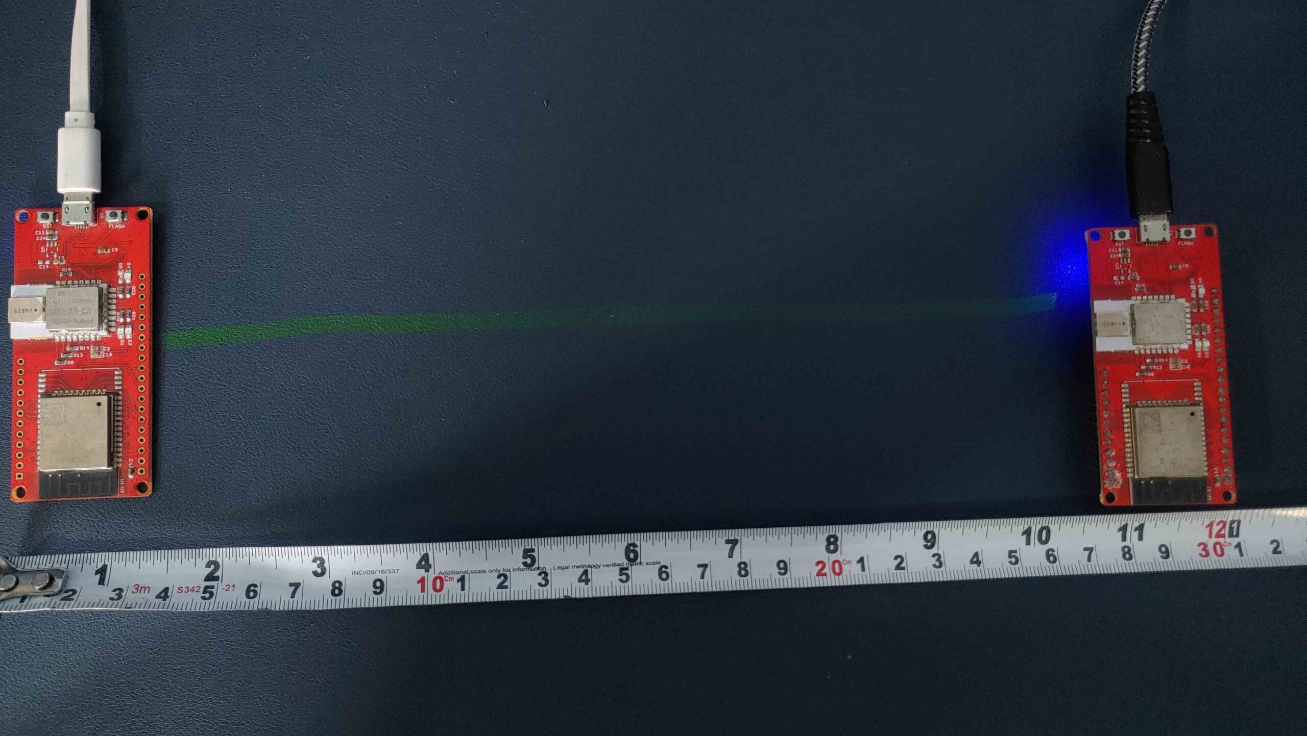
Open the serial monitor to view the distance measured from the anchor point.
We tested the ESP32 UWB boards and found they provided accurate distance measurements at different test points (e.g., 1m, 0.7m, 0.5m). The UWB board is now ready for use in other projects!

