In this tutorial I’ll show you how easily we can program our esp8266 Arduino ide Software I will upload a simple sketch of LED blinking to the ESP8266 board.
Espressif Systems (A Shanghai-based Semiconductor Company) has released a precious, pocket-sized WiFi-enabled microcontroller – ESP8266, at an incredible cost! For less than $3, it can monitor and control something from anywhere in the world
Arduino IDE allows for programming the ESP8266 chip using the Arduino IDE. This is a great development environment for programming the ESP8266 chip.
The most used programming languages for NodeMCU are MicroPython, Lua, and Arduino. They are all open-source and come with free development tools.
What is an ESP8266?
The ESP8266 is a low-cost Wi-Fi microchip with a full TCP/IP stack and microcontroller functionality. Although the chip was originally designed for use in Wi-Fi applications, manufactured by the Espressif system, a Chinese company. it can also be used in other applications such as Arduino IDE. The ESP8266 Arduino IDE is a development environment that allows for programming the ESP8266 chip using the Arduino IDE.
The first chip became known to the market with the ESP-01 module, designed by the company AI-Thinker. This little module permits other microcontrollers so you can use it to connect t to your Wi-Fi wireless network. connect NodeMCUto the Internet, a web server with real web pages, and let your smartphone connect to it.
Key Features.
- Wireless 802.11 b / g / n standards;
- Support STA / AP / STA + AP three operating modes;
- Built-in TCP / IP protocol stack to support multiple TCP Client connections (5 MAX);
- D0 ~ D8, SD1 ~ SD3: used as GPIO, PWM, IIC, etc. Port Drive 15mA;
- AD0: 1 channel ADC;
- Power input: 4.5V ~ 9V (10VMAX), USB-powered, providing USB debugging interface;
- Current job: keep sending: ≈70mA (200mA MAX), Standby:
- Transfer rate: 110-460800bps;
- Support UART / GPIO data communication interface;
- Remote firmware upgrade (OTA);
- Smart Link supports intelligent networking capabilities;
- Operating temperature: -40 ℃ ~ + 125 ℃;
- Drive Type: Dual high-power H-bridge driver
- Module Weight: about 7g
- Board Name: NodeMCU 1.0 (ESP-12E Module)
- USB-to-UART bridge chip: CP2102
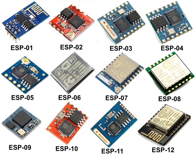
Types of ESP Modules
Let’s start with ESP Module:- These are programmable microcontroller-type boards, with a chipset from the company Espressif Systems, in the Arduino style, which can also run both compiled and interpreted Python-style languages.
ESP8266 Features
- The ESP8266 is a low-cost Wi-Fi microchip with a full TCP/IP stack and microcontroller capability. The chip first came to the attention of Western makers in August 2014 with the ESP-01 module, made by a third-party manufacturer, AI-Thinker.
- The ESP8266 was initially developed by Espressif Systems in China and is now produced by several manufacturers. It is widely used in low-cost Wi-Fi applications such as smart plugs and light switches.
- The ESP8266 has a Tensilica L106 32-bit microprocessor running at 80 MHz. The chip also has 128 KB of flash memory for storing code and data. The ESP8266 is capable of either running in standalone mode or be integrated into another device such as a microcontroller.
- The ESP8266 has a number of interesting features that make it attractive for use in a variety of applications.
- The ESP8266 is a meager cost. The ESP-01 module, for example, can be purchased for less than $5.
- The ESP8266 has a built-in Wi-Fi stack, so it does not need an external Wi-Fi module. This makes it very easy to add Wi-Fi connectivity to a project.
- The ESP8266 has a built-in TCP/IP stack, so it can connect to the Internet without the need for an external microcontroller.
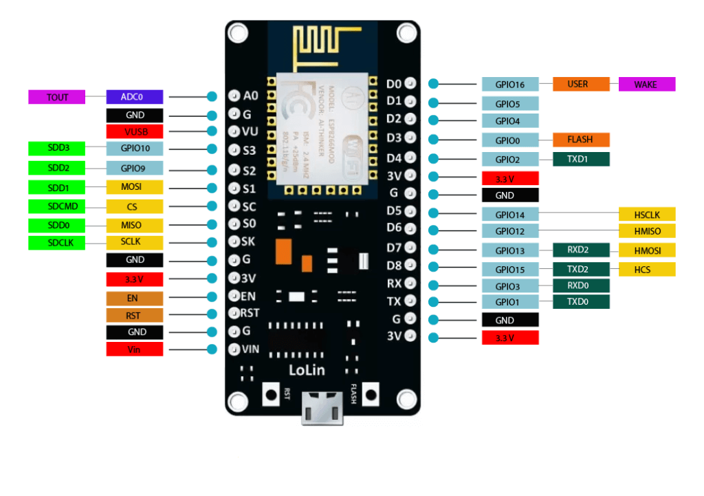
ESP8266 NodeMCU Pinout
Let us now look at the ESP8266 Nodemcu Pin diagram.
Adding ESP8266 Board in Arduino IDE
- First, we need to download the Arduino IDE program to upload code if you already installed it on your computer you can move ahead. or you can download it from Download Arduino IDE.
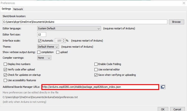
- After installing the IDE on your PC and opening the IDE, go to FILE > PREFERENCES To do this, we must open the File menu, and then Preferences. We will see this panel, at the bottom of the text box labelled Additional Card URLs Manager. Inside it, using copy and paste, you must enter the text indicated here:
|
1 |
http://arduino.esp8266.com/stable/package_esp8266com_index.json |
- Choose Preferences in the File menu and enter the copied code in the Additional Board Manager URLs. Then press the OK button.
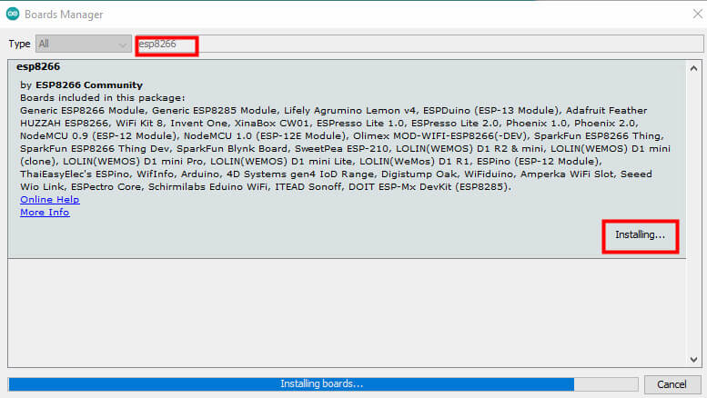
4. Go to Boards>boards manager from the Tools menu. Then install ESP8266 boards. After completing the installation, you will see the INSTALLED label on ESP8266 boards. Search the ESP8266 in
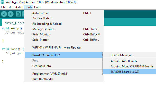
- Now we must go to the Tools menu, then select board
- Now search “ESP8266” click on “Install” and install the board to Arduino IDE
5. Now we can restart the Arduino IDE and we should be able to select the ESP8266 board in the Tools>Board menu.
After Done
- After installing the required drivers.
- Open the Arduino IDE.
- Open Board Manager from Tools > board > esp8266 and select the NodeMCU 1.0 board (ESP-12E Module)
- CPU frequency: 80Mhz
- Flash Size: 4M
- Upload speed: 115200
- PORT: Select Assign port only.
Program example:
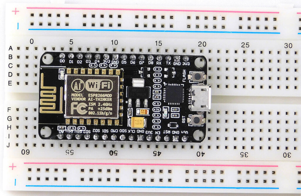
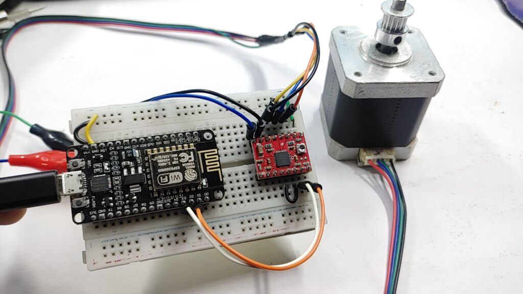
The NodeMCU is a development board that contains the built-in ESP-12E module, plus all the necessary support elements to communicate with it, including a USB connector, voltage regulator, reset button, and a “flash” button that is used to program the module, rows of plug-in pins, etc.
We will create a simple circuit to blink an LED on ESP8266 using the Arduino IDE to program them.
Important: in the next section, called “write the program “, when we define: output = 0 we refer to GPIO 0, and if we define: output = 2 we refer to GPIO 2. In the internal signature of ESP, it is defined as this. No need to worry about this, just remember that 0 refers to GPIO 0 and 2 refers to GPIO 2.
Write the program
The program to blink an LED is very simple: We will use the following code that we can cut/paste into the Arduino IDE.
|
1 2 3 4 5 6 7 8 9 10 11 12 13 14 15 16 17 |
int LED = 5; // Assign LED pin i.e: D1 on NodeMCU void setup() { // initialize GPIO 5 as an output pinMode(LED, OUTPUT); } void loop() { digitalWrite(LED, HIGH); // turn the LED on delay(1000); // wait for a second digitalWrite(LED, LOW); // turn the LED off delay(1000); // wait for a second } |
Conclusion
Once the code is uploaded, the LED will start blinking. You may need to tap the RST button to get your ESP8266 to begin running the sketch.
Shortly, we took the first steps in this tutorial with the NodeMCU ESP8266. We set up the Arduino programming environment, tested it, and made our first project. Soon, new tutorials using this amazing board will be published here on the blog. Stay tuned!

1 Comment
Pingback: How To Interface 16X2 LCD Display With NodeMCU Esp8266