In this project, we’ll use ESP8266 and AMG8833 thermal sensors to make a low-cost ESP8266 Thermal Imaging camera. We’ll collect the temperature readings data & display it in a graphical format such as a heatmap on the ILI9341 TFT Display. This setup can be used for various applications such as temperature monitoring, motion detection, and security systems, among other devices.
Required Material
Parts Used :
- Wemos D1 Mini Pro ( Amazon / AliExpress)
- AMG8833 Sensor ( Amazon / AliExpress)
- 2.8″ TFT Display ( Amazon / AliExpress)
- Jumper wires ( Amazon / AliExpress)
- Breadboard ( Amazon / AliExpress)
- 130k Resistor ( Amazon / AliExpress)
AMG8833 Sensor
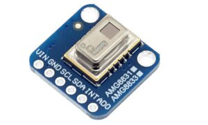
The AMG8833 is a low-power grid-eye infrared camera sensor camera that detects infrared radiation from objects or humans that converts it into a grid of 8×8 pixels array that is designed for use with lower power Infrared cameras. Interfacing AMG8833 Thermal Camera Sensor With Raspberry PI
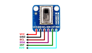
AMG8833 Sensor Pinout
AMG8833 Sensor features
- Temperature Range: 0°C to 80°C accuracy of ±2°C.
- Low Power Consumption: 140mW
- Interfacing Options:
-
Operating Voltage: 3/5V
- Resolution: 8×8 Thermopile Array (64 Pixel)
-
I2C Address: 0x69
-
Human Detection Distance: 7m or less (22.966ft)
-
Dimensions: 30 x 30 mm
Wiring Diagram – ESP8266 Thermal Imaging Camera
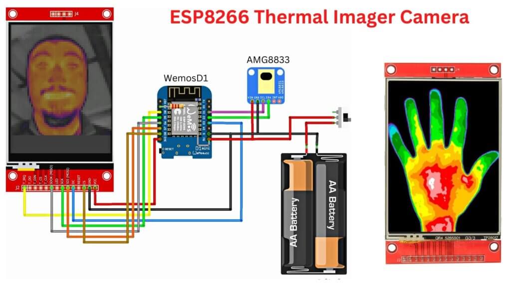
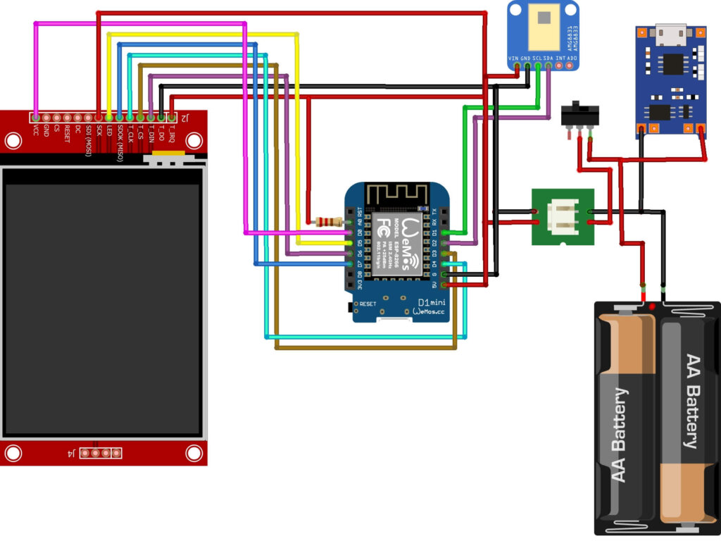
The wiring diagram is very easy. You have to connect the TFT display module ( ILI9341 ) pins with Wemos pins as per the schematic diagram. The schematic diagram is shown below.
You might prefer to follow the following pin mapping.
TFT Display->Wemos ( ESP8266 )
- T_IRQ >> 5V
- T_DO >> GND
- T_DIN >> D6
- T_CS >>D3
- T_CLK >> D4
- SDOK(MISO) >> D7
- LED >> D5
- SCK >> 5V
- VCC D0
AMG8833->Wemos ( ESP8266 )
- GND -> GND
- VCC -> 3-5V
- SCL -> D1
- SDA -> D2
Prepare the Arduino IDE for ESP8266 Board
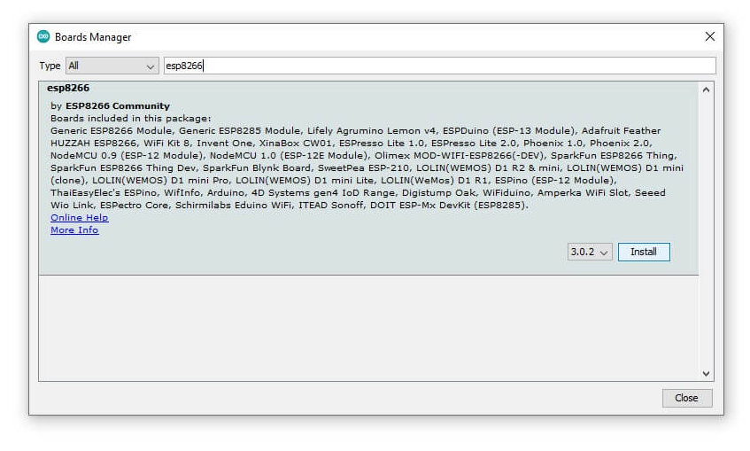
ESP8266 module is not part of Arduino-IDE, so we have to install it first. You can easily install it by going through the following steps: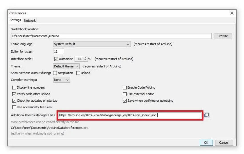
- Start Arduino IDE and open the Preferences window.
- Enter https://arduino.esp8266.com/stable/package_esp8266com_index.json into the File>Preferences>Additional Boards Manager URLs field of the Arduino IDE.
- Open Boards Manager from the IDE menu and install the correct ESP8266 board.
- Now you can choose LOLIN(WEMOS) D1 R2 & mini!
Download the Code and Libraries
Libraries:
- Adafruit-GFX-Library by Adafruit
- Adafruit_ILI9341 by Adafruit
- Adafruit_AMG88xx by Adafruit
- ESP8266 (folders ending with TFT_eSPI), TFT_eSPI import ZIP from ( https://github.com/Bodmer/TFT_eSPI )
Note- For ESP8266 versions in the TFT_eSPI library folder, uncomment the following lines in User_Setup.h:
|
1 |
<span class="">#define ILI9341_DRIVER</span> |
Additional
|
1 2 3 4 |
#define TFT_CS PIN_D8 // Chip select control pin D8 #define TFT_DC PIN_D3 // Data Command control pin //#define TFT_RST PIN_D4 // Reset pin (could connect to NodeMCU RST, see next line) #define TFT_RST -1 // Set TFT_RST to -1 if the display RESET is connected to NodeMCU RST or 3.3V |
More and more editing in User_setup.h is unnecessary.
After downloading the library unzip it and installed it in your Arduino IDE by going to Sketch > Include Library > Manage Libraries (or using the library manager).
Arduino Code:
|
1 2 3 4 5 6 7 8 9 10 11 12 13 14 15 16 17 18 19 20 21 22 23 24 25 26 27 28 29 30 31 32 33 34 35 36 37 38 39 40 41 42 43 44 45 46 47 48 49 50 51 52 53 54 55 56 57 58 59 60 61 62 63 64 65 66 67 68 69 70 71 72 73 74 75 76 77 78 79 80 81 82 83 84 85 86 87 88 89 90 91 92 93 94 95 96 97 98 99 100 101 102 103 104 105 106 107 108 109 110 111 112 113 114 115 116 117 118 119 120 121 122 123 124 125 126 127 128 129 130 131 132 133 134 135 136 137 138 139 140 141 142 143 144 145 146 147 148 149 150 151 152 153 154 155 156 157 158 159 160 161 162 163 164 165 166 167 168 169 170 171 172 173 174 175 176 177 178 179 180 181 182 183 184 185 186 187 188 189 190 191 192 193 194 195 196 197 198 199 200 201 202 203 204 205 206 207 208 209 210 211 212 213 214 215 216 217 218 219 220 221 222 223 224 225 226 227 228 229 230 231 232 233 234 235 236 237 238 239 240 241 242 243 244 245 246 247 248 249 250 251 252 253 254 255 256 257 258 259 260 261 262 263 264 265 266 267 268 269 270 271 272 273 274 275 276 277 278 279 280 281 282 283 284 285 286 287 288 289 290 291 292 293 294 295 296 297 298 299 300 301 302 303 304 305 306 307 308 309 310 311 312 313 314 315 316 317 318 319 320 321 322 323 324 325 326 327 328 329 330 331 332 333 334 335 336 337 338 339 340 341 342 343 344 345 346 347 348 349 350 351 352 353 354 355 356 357 358 359 360 361 362 363 364 365 366 367 368 369 370 371 372 373 374 375 376 377 378 379 380 381 382 383 384 385 386 387 388 389 390 391 392 393 394 395 396 397 398 399 400 401 402 403 404 405 406 407 408 409 410 411 412 413 414 415 416 417 418 419 420 421 422 423 424 425 426 427 428 429 430 431 432 433 434 435 436 437 438 439 440 441 442 443 444 445 446 447 448 449 450 451 452 453 454 455 456 457 458 459 460 461 462 463 464 465 466 467 468 469 470 471 472 473 474 475 476 477 478 479 480 481 482 483 484 485 486 487 488 489 490 491 492 493 494 495 496 497 498 499 500 501 502 503 504 505 506 507 508 509 510 511 512 513 514 515 516 517 518 519 520 521 522 523 524 525 526 527 528 529 530 531 532 533 534 535 536 537 538 539 540 541 542 543 544 545 546 547 548 |
#ifdef ESP8266 #include <TFT_eSPI.h> #else #include <Fonts/FreeMonoBoldOblique12pt7b.h> #define PIN_CS 15//10 // chip select for the display #define PIN_DC 0//9 // d/c pin for the display #endif #include <Adafruit_ILI9341.h> #include <Adafruit_AMG88xx.h> // thermal camera lib #define PIN_INT D0 // Interrupt from touch for autoscale/scale // constants for the cute little keypad #define KEYPAD_TOP 15 #define KEYPAD_LEFT 50 #define BUTTON_W 60 #define BUTTON_H 30 #define BUTTON_SPACING_X 10 #define BUTTON_SPACING_Y 10 #define BUTTON_TEXTSIZE 2 // fire up the display using a very fast driver // this next line is for my modified library where I pass the screen dimensions in--that way i can use the same lib for my 3.5", 2.8" and other sizes // ILI9341_t3 Display = ILI9341_t3(PIN_CS, PIN_DC, 240, 320); // you will need to use this line #ifdef ESP8266 TFT_eSPI Display = TFT_eSPI(); #else Adafruit_ILI9341 Display = Adafruit_ILI9341(PIN_CS, PIN_DC); #endif // create some colors for the keypad buttons #define C_BLUE Display.color565(0,0,255) #define C_RED Display.color565(255,0,0) #define C_GREEN Display.color565(0,255,0) #define C_WHITE Display.color565(255,255,255) #define C_BLACK Display.color565(0,0,0) #define C_LTGREY Display.color565(200,200,200) #define C_DKGREY Display.color565(80,80,80) #define C_GREY Display.color565(127,127,127) // Added for measure Temp boolean measure = true; uint16_t centerTemp; unsigned long tempTime = millis(); unsigned long batteryTime = 1; // create some text for the keypad butons char KeyPadBtnText[12][5] = {"1", "2", "3", "4", "5", "6", "7", "8", "9", "Done", "0", "Clr" }; // define some colors for the keypad buttons uint16_t KeyPadBtnColor[12] = {C_BLUE, C_BLUE, C_BLUE, C_BLUE, C_BLUE, C_BLUE, C_BLUE, C_BLUE, C_BLUE, C_GREEN, C_BLUE, C_RED }; // start with some initial colors float MinTemp = 25; float MaxTemp = 35; // variables for interpolated colors byte red, green, blue; // variables for row/column interpolation byte i, j, k, row, col, incr; float intPoint, val, a, b, c, d, ii; byte aLow, aHigh; // size of a display "pixel" byte BoxWidth = 3; byte BoxHeight = 3; int x, y; char buf[20]; // variable to toggle the display grid int ShowGrid = -1; int DefaultTemp = -1; // array for the 8 x 8 measured pixels float pixels[64]; // array for the interpolated array float HDTemp[80][80]; // create the keypad buttons // note the ILI9438_3t library makes use of the Adafruit_GFX library (which makes use of the Adafruit_button library) Adafruit_GFX_Button KeyPadBtn[12]; // create the camara object Adafruit_AMG88xx ThermalSensor; // create the touch screen object //UTouch Touch( 2, 3, 4, 5, 6); void setup() { Serial.begin(115200); // Set A0 to input for battery measurement pinMode(A0, INPUT); // start the display and set the background to black Display.begin(); Display.fillScreen(C_BLACK); // initialize the touch screen and set location precision //Touch.InitTouch(); //Touch.setPrecision(PREC_EXTREME); // create the keypad buttons // for (row = 0; row < 4; row++) { // for (col = 0; col < 3; col++) { // KeyPadBtn[col + row * 3].initButton(&Display, BUTTON_H + BUTTON_SPACING_X + KEYPAD_LEFT + col * (BUTTON_W + BUTTON_SPACING_X ), // KEYPAD_TOP + 2 * BUTTON_H + row * (BUTTON_H + BUTTON_SPACING_Y), // BUTTON_W, BUTTON_H, C_WHITE, KeyPadBtnColor[col + row * 3], C_WHITE, // KeyPadBtnText[col + row * 3], BUTTON_TEXTSIZE); // } // } // set display rotation (you may need to change to 0 depending on your display Display.setRotation(0); // show a cute splash screen (paint text twice to show a little shadow // Display.setFont(&FreeMonoBoldOblique12pt7b); // Display.setFont(DroidSans_40); Display.setTextSize(2); Display.setCursor(62, 61); Display.setTextColor(C_WHITE, C_BLACK); Display.print("Thermal"); //Display.setFont(DroidSans_40); Display.setCursor(60, 60); Display.setTextColor(C_BLUE); Display.print("Thermal"); //Display.setFont(Arial_48_Bold_Italic); Display.setCursor(92, 101); Display.setTextColor(C_WHITE, C_BLACK); Display.print("Camera"); //Display.setFont(Arial_48_Bold_Italic); Display.setCursor(90, 100); Display.setTextColor(C_RED); Display.print("Camera"); // let sensor boot up bool status = ThermalSensor.begin(); delay(100); // check status and display results if (!status) { while (1) { //Display.setFont(DroidSans_20); Display.setCursor(20, 180); Display.setTextColor(C_RED, C_BLACK); Display.print("Sensor: FAIL"); delay(500); //Display.setFont(DroidSans_20); Display.setCursor(20, 180); Display.setTextColor(C_BLACK, C_BLACK); Display.print("Sensor: FAIL"); delay(500); } } else { //Display.setFont(DroidSans_20); Display.setCursor(20, 180); Display.setTextColor(C_GREEN, C_BLACK); Display.print("Sensor: FOUND"); } // read the camera for initial testing ThermalSensor.readPixels(pixels); // check status and display results if (pixels[0] < 0) { while (1) { //Display.setFont(DroidSans_20); Display.setCursor(20, 210); Display.setTextColor(C_RED, C_BLACK); Display.print("Readings: FAIL"); delay(500); //Display.setFont(DroidSans_20); Display.setCursor(20, 210); Display.setTextColor(C_BLACK, C_BLACK); Display.print("Readings: FAIL"); delay(500); } } else { // Display.setFont(DroidSans_20); Display.setCursor(20, 210); Display.setTextColor(C_GREEN, C_BLACK); Display.print("Readings: OK"); delay(2000); } // set display rotation and clear the fonts..the rotation of this display is a bit weird //Display.setFontAdafruit(); Display.fillScreen(C_BLACK); // Display.setFont(); // get the cutoff points for the color interpolation routines // note this function called when the temp scale is changed Getabcd(); // draw a cute legend with the scale that matches the sensors max and min DrawLegend(); // draw a large white border for the temperature area Display.fillRect(10, 10, 220, 220, C_WHITE); } void loop() { // if someone touched the screen do something with it // if (Touch.dataAvailable()) { // ProcessTouch(); // } if (digitalRead(PIN_INT) == false) { SetTempScale(); if (millis() - tempTime > 2000) { measure = !measure; tempTime = millis(); Display.fillRect (0, 300, 100, 16, ILI9341_BLACK); } } else { tempTime = millis(); } // read the sensor ThermalSensor.readPixels(pixels); // now that we have an 8 x 8 sensor array // interpolate to get a bigger screen InterpolateRows(); // now that we have row data with 70 columns // interpolate each of the 70 columns // forget Arduino..no where near fast enough..Teensy at > 72 mhz is the starting point InterpolateCols(); // display the 70 x 70 array DisplayGradient(); // Update battery everx 30s if (batteryTime < millis()) { drawBattery(); batteryTime = millis() + 30000; } } // interplation function to create 70 columns for 8 rows void InterpolateRows() { // interpolate the 8 rows (interpolate the 70 column points between the 8 sensor pixels first) for (row = 0; row < 8; row ++) { for (col = 0; col < 70; col ++) { // get the first array point, then the next // also need to bump by 8 for the subsequent rows aLow = col / 10 + (row * 8); aHigh = (col / 10) + 1 + (row * 8); // get the amount to interpolate for each of the 10 columns // here were doing simple linear interpolation mainly to keep performace high and // display is 5-6-5 color palet so fancy interpolation will get lost in low color depth intPoint = (( pixels[aHigh] - pixels[aLow] ) / 10.0 ); // determine how much to bump each column (basically 0-9) incr = col % 10; // find the interpolated value val = (intPoint * incr ) + pixels[aLow]; // store in the 70 x 70 array // since display is pointing away, reverse row to transpose row data HDTemp[ (7 - row) * 10][col] = val; } } } // interplation function to interpolate 70 columns from the interpolated rows void InterpolateCols() { // then interpolate the 70 rows between the 8 sensor points for (col = 0; col < 70; col ++) { for (row = 0; row < 70; row ++) { // get the first array point, then the next // also need to bump by 8 for the subsequent cols aLow = (row / 10 ) * 10; aHigh = aLow + 10; // get the amount to interpolate for each of the 10 columns // here were doing simple linear interpolation mainly to keep performace high and // display is 5-6-5 color palet so fancy interpolation will get lost in low color depth intPoint = (( HDTemp[aHigh][col] - HDTemp[aLow][col] ) / 10.0 ); // determine how much to bump each column (basically 0-9) incr = row % 10; // find the interpolated value val = (intPoint * incr ) + HDTemp[aLow][col]; // store in the 70 x 70 array HDTemp[ row ][col] = val; } } } // function to display the results void DisplayGradient() { // rip through 70 rows for (row = 0; row < 70; row ++) { // fast way to draw a non-flicker grid--just make every 10 pixels 2x2 as opposed to 3x3 // drawing lines after the grid will just flicker too much if (ShowGrid < 0) { BoxWidth = 3; } else { if ((row % 10 == 9) ) { BoxWidth = 2; } else { BoxWidth = 3; } } // then rip through each 70 cols for (col = 0; col < 70; col++) { // fast way to draw a non-flicker grid--just make every 10 pixels 2x2 as opposed to 3x3 if (ShowGrid < 0) { BoxHeight = 3; } else { if ( (col % 10 == 9)) { BoxHeight = 2; } else { BoxHeight = 3; } } // finally we can draw each the 70 x 70 points, note the call to get interpolated color Display.fillRect((row * 3) + 15, (col * 3) + 15, BoxWidth, BoxHeight, GetColor(HDTemp[row][col])); if (measure == true && row == 36 && col == 36) { drawMeasurement(); //Draw after center pixels to reduce flickering } } } } // my fast yet effective color interpolation routine uint16_t GetColor(float val) { /* pass in value and figure out R G B several published ways to do this I basically graphed R G B and developed simple linear equations again a 5-6-5 color display will not need accurate temp to R G B color calculation equations based on http://web-tech.ga-usa.com/2012/05/creating-a-custom-hot-to-cold-temperature-color-gradient-for-use-with-rrdtool/index.html */ red = constrain(255.0 / (c - b) * val - ((b * 255.0) / (c - b)), 0, 255); if ((val > MinTemp) & (val < a)) { green = constrain(255.0 / (a - MinTemp) * val - (255.0 * MinTemp) / (a - MinTemp), 0, 255); } else if ((val >= a) & (val <= c)) { green = 255; } else if (val > c) { green = constrain(255.0 / (c - d) * val - (d * 255.0) / (c - d), 0, 255); } else if ((val > d) | (val < a)) { green = 0; } if (val <= b) { blue = constrain(255.0 / (a - b) * val - (255.0 * b) / (a - b), 0, 255); } else if ((val > b) & (val <= d)) { blue = 0; } else if (val > d) { blue = constrain(240.0 / (MaxTemp - d) * val - (d * 240.0) / (MaxTemp - d), 0, 240); } // use the displays color mapping function to get 5-6-5 color palet (R=5 bits, G=6 bits, B-5 bits) return Display.color565(red, green, blue); } // function to automatically set the max / min scale based on adding an offset to the average temp from the 8 x 8 array // you could also try setting max and min based on the actual max min void SetTempScale() { if (false ) { //DefaultTemp < 0) { MinTemp = 25; MaxTemp = 35; Getabcd(); DrawLegend(); } else { MinTemp = 255; MaxTemp = 0; for (i = 0; i < 64; i++) { MinTemp = min(MinTemp, pixels[i]); //MaxTemp = max(MaxTemp, pixels[i]); if (pixels[i] > MaxTemp) { MaxTemp = pixels[i];} } MaxTemp = MaxTemp + 5.0; MinTemp = MinTemp + 3.0; Getabcd(); DrawLegend(); } } // function to get the cutoff points in the temp vs RGB graph void Getabcd() { a = MinTemp + (MaxTemp - MinTemp) * 0.2121; b = MinTemp + (MaxTemp - MinTemp) * 0.3182; c = MinTemp + (MaxTemp - MinTemp) * 0.4242; d = MinTemp + (MaxTemp - MinTemp) * 0.8182; } // function to handle screen touches //void ProcessTouch() { // // Touch.read(); // // x = Touch.getX(); // y = Touch.getY(); // yea i know better to have buttons // if (x > 200) { // if (y < 80) { // KeyPad(MaxTemp); // } // else if (y > 160) { // KeyPad(MinTemp); // } // else { // DefaultTemp = DefaultTemp * -1; // SetTempScale(); // } // } // else if (x <= 200) { // toggle grid // ShowGrid = ShowGrid * -1; // if (ShowGrid > 0) { // Display.fillRect(15, 15, 210, 210, C_BLACK); // } // } //} // function to draw a cute little legend void DrawLegend() { // my cute little color legend with max and min text j = 0; float inc = (MaxTemp - MinTemp ) / 220.0; for (ii = MinTemp; ii < MaxTemp; ii += inc) { // Display.drawFastHLine(10, 255 - j++, 30, GetColor(ii)); Display.drawFastVLine(10 + j++, 255, 30, GetColor(ii)); } Display.setTextSize(2); Display.setCursor(10, 235); Display.setTextColor(C_WHITE, C_BLACK); sprintf(buf, "%2d/%2d", MinTemp, (int) (MinTemp * 1.8) + 32); // Display.fillRect(233, 15, 94, 22, C_BLACK); // Display.setFont(Arial_14); Display.print(buf); Display.setTextSize(2); // Display.setFont(Arial_24_Bold); Display.setCursor(170, 235); Display.setTextColor(C_WHITE, C_BLACK); sprintf(buf, "%2d/%2d", MaxTemp, (int) (MaxTemp * 1.8) + 32); // Display.fillRect(233, 215, 94, 55, C_BLACK); // Display.setFont(Arial_14); Display.print(buf); } // Draw a circle + measured value void drawMeasurement() { // Mark center measurement Display.drawCircle(120, 120, 3, ILI9341_WHITE); // Measure and print center temperature centerTemp = pixels[27]; Display.setCursor(10, 300); Display.setTextColor(ILI9341_WHITE, ILI9341_BLACK); Display.setTextSize(2); sprintf(buf, "%s:%2d", "Temp", centerTemp); Display.print(buf); } int measureBattery() { uint16_t adcValue = analogRead(A0); int volt = adcValue / 102.3 * 4.5;// Using 130kOhm resistor return volt; } // Draw battery symbol void drawBattery() { int volt = measureBattery() - 32; // range from 3.2V - 4.2V volt = max (volt, 1); volt = min (volt, 10); // draw battery Display.drawRect(198, 304, 30, 10, C_WHITE); Display.fillRect(227, 306, 3, 6, C_WHITE); Display.fillRect(199, 305, 28, 8, C_BLACK); if (volt > 3)Display.fillRect(199, 305, volt * 3 - 2 , 8, C_GREEN); else Display.fillRect(199, 305, volt * 3 - 2, 8, C_RED); } // end of code |
After installing Arduino IDE and downloading all the libraries we can transfer to upload the code into the ESP8266 board ( Wemos D1 Mini board)
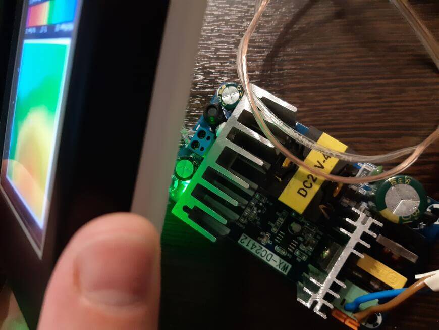
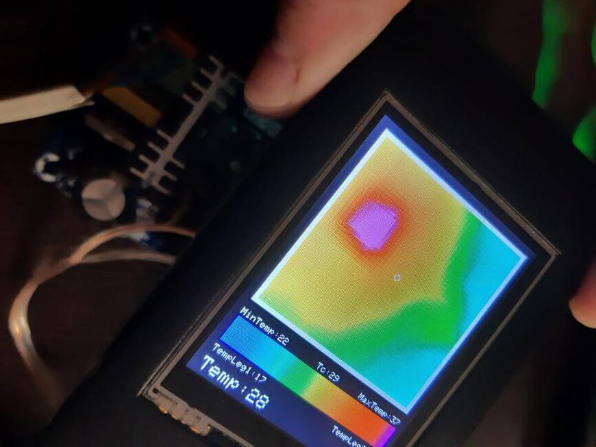
Testing

1 Comment
Wow