In this Flow Sensor with Arduino tutorial, we will go over how to measure liquid flow rate using an Arduino board. flow sensors are used to measure the rate of liquid flow. There are different types of flow sensors in the market, but for this tutorial, we will be using a hall-effect flow sensor. These types of flow sensors are non-invasive, meaning that they do not come in contact with the liquid.
flow measurement projects like this can be absolutely beneficial in different applications such as irrigation systems for agriculture, gardening, monitoring water usage in households, industrial automation, and drink dispensers.
By accurately measuring the flow rate, it is possible to optimize the use of resources and minimize waste. you can monitor and control the usage of water or other liquids.
Required Material
- Arduino Board – Amazon | AliExpress
- Flow Sensor – Amazon | AliExpress
- Jumper Wires – Amazon | AliExpress
- Breadboard – Amazon | AliExpress
- USB Cable – Amazon | AliExpress
Arduino Flow Sensor Module
The Water flow sensor is a type of flow sensor that is developed to calculate the flow of water via a pipe. Water flow sensors are used in many applications, including irrigation systems, water treatment plants, and industrial areas that require the exact measurement of water flow rates.
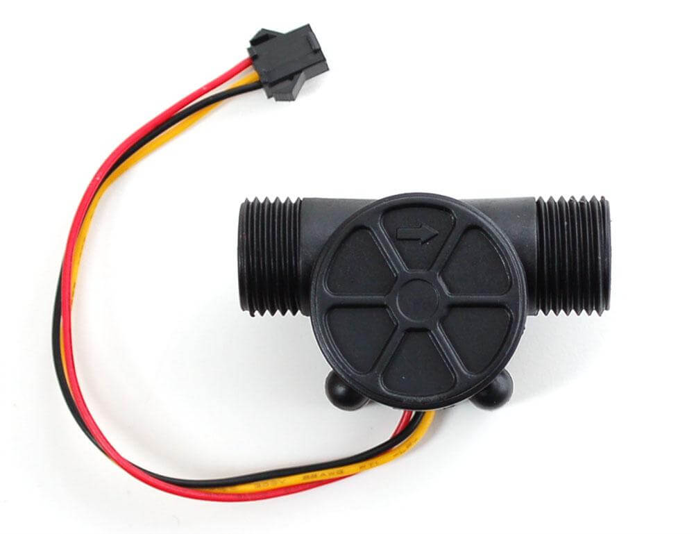
A Hall effect water flow sensor is a device that measures the rate of flow of water through a pipe or conduit. The sensor uses the Hall effect to measure the rate of flow.
There are different types of water flow sensors available in the market, including mechanical, magnetic, ultrasonic, and turbine flow sensors.
Flow Sensor Pinout
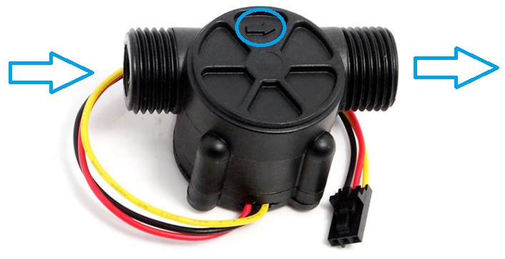
The sensor comes with three wires: red, black, and yellow.
By counting the pulses from the output of the sensor, you can easily calculate the water flow rate. With three wires sticking out of its head, the sensor can provide a switched output.
- Power supply pin
- Ground pin
- Signal pin
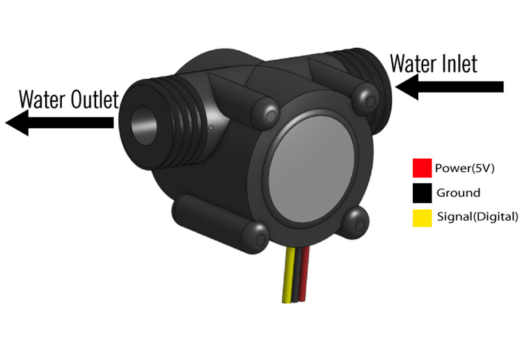
Flow Sensor Features:
- Compact, Easy to Install
- High-Quality Hall Effect Sensor
- RoHS Compliant
- Flow sensors provide affordable, accurate water-flow-rate measures for water management applications.
- Compatible with Arduino & other microcontrollers.
- Low power consumption.
- Stable and long-lasting.
- Suitable for a wide range of water flow monitoring.
- Water treatment plants.
Flow Sensor Specifications:
- Model: YF-S201
- Operating voltage: 5V – 18V DC
- Current Consumption: 15mA (5V)
- Flow Rate Range: 0.3-6L/min
- Operating temperature: -25ºC to 80ºC
- Output Signal: Digital Pulse Signal
- Output Pulse High Level: 4.5V
- Output Pulse Low Level: 0.5V
- Maximum Water Pressure: 1.75MPa
- Water Pipe Diameter: 1/2 inch
- Flow rate pulse factors: Frequency (Hz) = 7.5 * Flow rate (L/min)
Application of Flow Sensor:
Some common applications of flow sensors
- Water management
- Automotive industry
- Medical applications
- Agriculture sector
- Gas flow rates
- Food processing
- Mining industry
- Water recycling
- Coffee machines, etc.
Working of Hall Effect Water Flow Sensor
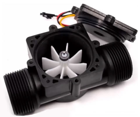
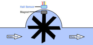
The YFS201 Hall Effect Water Flow Sensor is a device that uses the Hall effect principle to measure the flow of water through a pipe. the sensor uses a turbine or paddle wheel to rotate as liquid flows through it. rotation of the wheel generates electrical pulses that are counted by the microcontroller, which can be used to calculate the flow rate of the liquid.
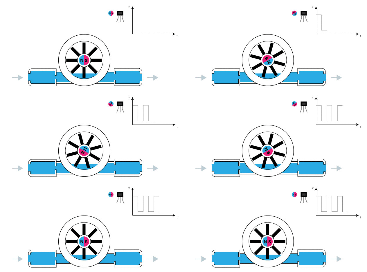
When water flows through the flow sensor, a magnetic field is created, which is detected by the Hall effect sensor. and this data is then converted into an electrical signal that can be used to measure and monitor the flow rate.
How To Calibrate Flow Sensor with Arduino
To calibrate a flow sensor, you will need to know the flow rate and the sensor’s accuracy, a formula to convert pulse frequency to flow rate.
Flow rate (Liters/minute) = Pulse frequency (Hz) / 7.5
To convert the flow rate from Liters/minute to Liters/hour, we can multiply by 60:
Flow Rate (Litres/hour) = (Pulse frequency (Hz) x 60) / (7.5 x Q)
Where:
- Pulse frequency is the frequency of the pulses generated by the flow sensor module
- Q is the flow rate in Liters/minute
The flow sensor generates pulses at a frequency directly balanced with the flow rate of the liquid passing through it. the constant of proportionality is 7.5, which is determined by the datasheet of the flow sensor.
By measuring the frequency of pulses generated by the flow sensor, we can define the flow rate of the liquid passing through it by means of the formula.
The arrow on the back side of the sensor means the correct flow direction, and you should make sure to install the sensor accordingly.
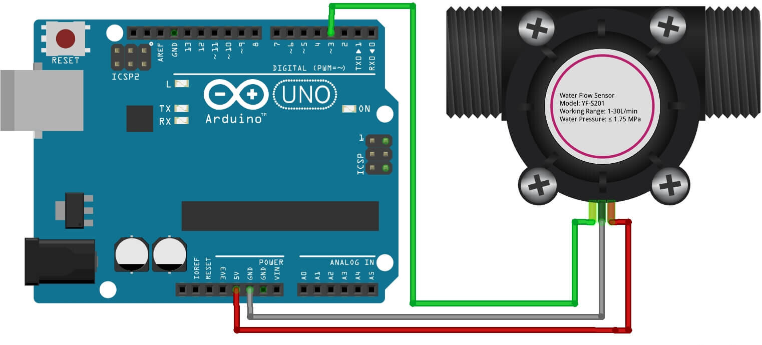
Schematic Diagram – Flow Sensor with Arduino
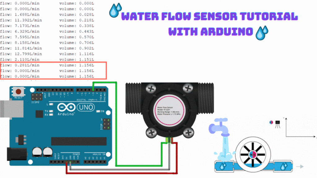
The YFS201 Hall Effect Water Flow Sensor has three pins: VCC, GND, and OUT. To connect the sensor to an Arduino board.
- Connect VCC pin of the sensor to the 5V
- Connect GND pin of the sensor to the GND
- Connect OUT pin of the sensor to the digital pin D3
The connections are straight & simple, see the above circuit schematic image.
Source Code
|
1 2 3 4 5 6 7 8 9 10 11 12 13 14 15 16 17 18 19 20 21 22 23 24 25 26 27 28 29 30 31 32 33 34 35 36 37 38 39 40 41 42 43 44 45 46 47 48 49 50 51 52 53 54 55 56 |
volatile int NumPulses; //variable for the number of pulses received int PinSensor = 3; //Sensor connected to pin 2 float factor_conversion=7.11; //to convert from frequency to flow rate float volume=0; long dt=0; //time variation for each loop long t0=0; //millis() from the previous loop //---Function executed on interrupt---- void CountPulse () { NumPulses++; //increment the pulse variable } //---Function to obtain pulse frequency---------- int ObtenerNumPulses() { int frequency; NumPulses = 0; //We set the number of pulses to 0 interrupts(); //Enable interrupts delay(1000); //sample 1 second noInterrupts(); // Disable interrupts frequency=NumPulses;//Hz(pulses per second) return frequency; } void setup() { Serial.begin(9600); pinMode(PinSensor, INPUT); attachInterrupt(1,CountPulse,RISING);//(Interrupt 0(Pin2),function,Rising Edge) Serial.println ("Send 'S' to reset volume to 0 Liters"); t0=millis(); } void loop () { if (Serial.available()) { if(Serial.read()=='S')volume=0;//reset the volume if we receive 'r' } float frequency=ObtenerNumPulses(); // get the frequency of the pulses in Hz float flow_L_m=frequency/factor_conversion; //calculate the flow in L/m dt=millis()-t0; ////calculate the time variation t0=millis(); volume=volume+(flow_L_m/60)*(dt/1000); // volume(L)=flow(L/s)*time(s) //-----Send through the serial port--------------- Serial.print ("flow: "); Serial.print (flow_L_m,3); Serial.print ("L/min\tvolume: "); Serial.print (volume,3); Serial.println ("L"); } |
Working
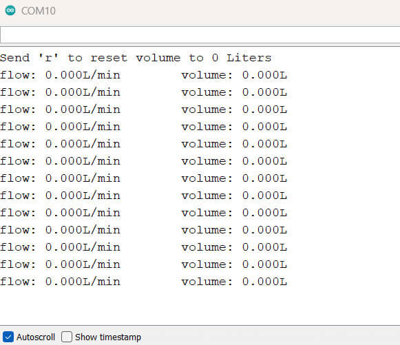
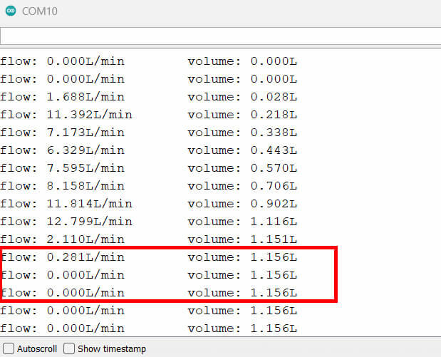
The serial monitor shows the flow rate and the volume of the current data.
To reset the volume measurement you must send the letter “s” and the volume will start from 0.
Check the Video On Youtube


