Introduction
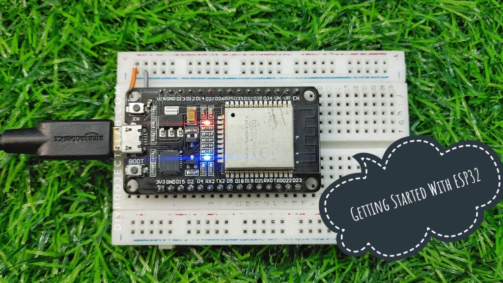
In this guide, we will show you how to Getting Started With ESP32 & How to Setting up Arduino IDE for ESP32. how to set it up with the Arduino IDE, and how to begin using it for basic projects. The ESP32 is ideal for IoT applications that require low power consumption, such as battery-operated devices. The ESP32 is also one of the most popular microcontrollers
What is ESP32?
ESP32 is a series of low-cost, low-power systems-on-a-chip (SoC) microcontrollers with integrated Wi-Fi and dual-mode Bluetooth capabilities. The ESP32 chip is a successor to the popular ESP8266 chip. ESP32 is a highly integrated chip that combines WiFi and Bluetooth wireless capabilities with a dual-core processor.
The ESP32 series of chips are widely used in a variety of applications, including IoT, automotive, industrial, and home automation.
The ESP32 series of chips offers a wide range of features and capabilities, including: -Integrated Wi-Fi and dual-mode Bluetooth -Low cost -Low power consumption -High performance -Rich set of peripherals -Flexible hardware development platform
ESP32 Features
- CPU: Xtensa dual-core (or single-core) 32-bit LX6 microprocessor, operating at 160 or 240 MHz and performing at up to 600 DMIPS
- Ultra-low power (ULP) co-processor
- Memory: 520 KiB SRAM
- WiFi: 802.11 b/g/n/e/i
- Bluetooth: v4.2 BR/EDR and BLE
- 12-bit SAR ADC up to 18 channels
- 2 × 8-bit DACs
- 4 × SPI
- 2 × I2S interfaces
- 2 × I2C interfaces
- 3 × UART
- Wake up from GPIO interrupt, timer, and ADC measurements.
And these are just some data. A complete list of ESP32 features can be found in the component’s datasheet.
Talking especially of the ESP32 module, the one we are going to use is similar to the already learned ESP8266 NodeMCU ESP-12, a very popular module from the ESP8266 line.
ESP32 Pinout
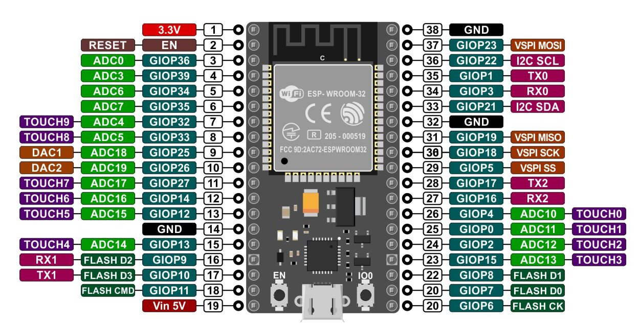
Let us now look at the ESP32 Pin diagram. In the image below we have the pinout of the ESP-WROOM-32:
- GPIO ports – GPIO pins for General Purpose Input/Output, are pins responsible for the input and output of digital signals. They are each capable of supplying a maximum of 12 mA of current.
- Touch ports – These pins work as capacitive sensors, that is, they react when there is a change in their state. A simple example is touching it: this will start a process of heat exchange between two different bodies, where the sensor will perceive and emit signals to the ESP. This board has 10 touch pins.
- ADC –The ADCs ( Analog Digital Converter ) are famous in the electronics field. They convert analogue quantities (a car pointer speedometer, for example) into digital quantities (a digital speedometer, for example). According to the ESP diagram, it has 16 pins with this capability.
- Multiple pins – The ESP32 has 3 GND ports, 1 3.3V port and 1 5V port (which in the diagram is identified by Vin, since it can be used to power the board if it is not connected by the USB cable). There are also other pins, such as RX and TX, CLK, MISO and others.
Getting Started With ESP32 -Programming the ESP32
The ESP32 can be programmed using many different development environments. Code can be written in C++ (like Arduino) or in MicroPython.
Programming ESP32 with Arduino IDE
Let’s test the ESP32 running the well-known “blink led”. The program itself is the least important thing, as configuring the Arduino IDE to program the ESP32 requires a certain amount of attention so that nothing goes wrong.
we will focus on programming the ESP32 in the Arduino IDE. The Arduino IDE is a popular choice for many makers because it is easy to use and has a large community of users who can provide support and resources. Before we get started, you will need to download and install the Arduino IDE.
You can find the latest version here: https://www.arduino.cc/en/Main/Software
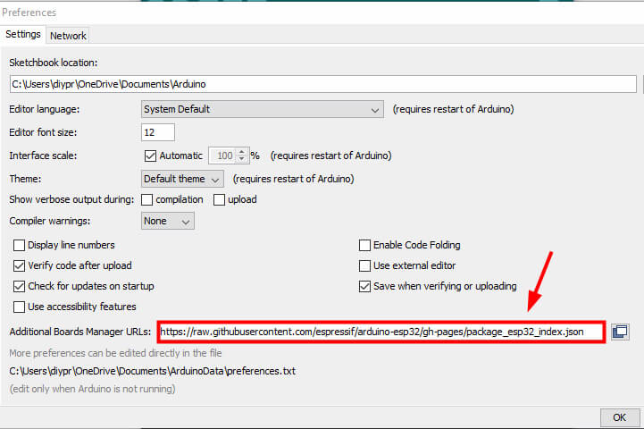
Once the Arduino IDE is installed, open it and go to File > Preferences. In the “Additional Board Manager URLs” field, enter the following URL:
Once you have the IDE installed, launch it and open the Preferences window. In the preferences window, copy and paste the following URL into the “Additional Board Manager URLs” field:
|
1 |
https://raw.githubusercontent.com/espressif/arduino-esp32/gh-pages/package_esp32_index.json |
- Click “OK” to close the preferences window.
- Next, you will need to use the new access to actually add the ESP32 boards to your Arduino IDE. You do that by following this process:
- Next, open the Board Manager by moving to Tools > Board > Board Manager. In the Board Manager, search
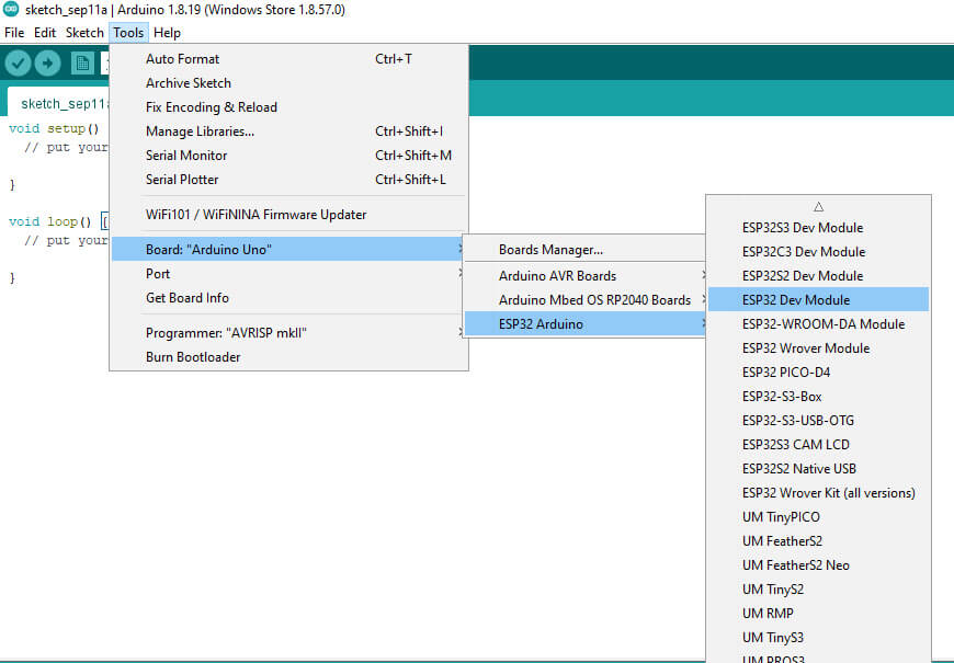
- In the Arduino IDE click on the Tools menu on the top menu bar.
- Scroll down to the Board: entry (i.e. Board: Arduino/Genuino Uno).
- A submenu will open when you highlight the Board: entry.
- At the top of the submenu is Boards Manager. Click on it to open the Boards Manager box.
- In the search box in the Boards Manager enter “esp32”.
- You should see an entry for “esp32 by Espressif Systems”. Highlight this entry and click on the Install button.
- This will install the ESP32 boards into your Arduino IDE
Plug the ESP32 board into your computer. With your Arduino IDE open, follow these steps:
- Select your Board in Tools > Board menu (in my case it’s the ESP32 Dev Module)
- select the COM port of your board and go to files > examples > basics > blink and upload the code to your esp32 board
|
1 2 3 4 5 6 7 8 9 10 |
int LED_BUILTIN = 2; void setup() { pinMode (LED_BUILTIN, OUTPUT); } void loop() { digitalWrite(LED_BUILTIN, HIGH); delay(1000); digitalWrite(LED_BUILTIN, LOW); delay(1000); } |
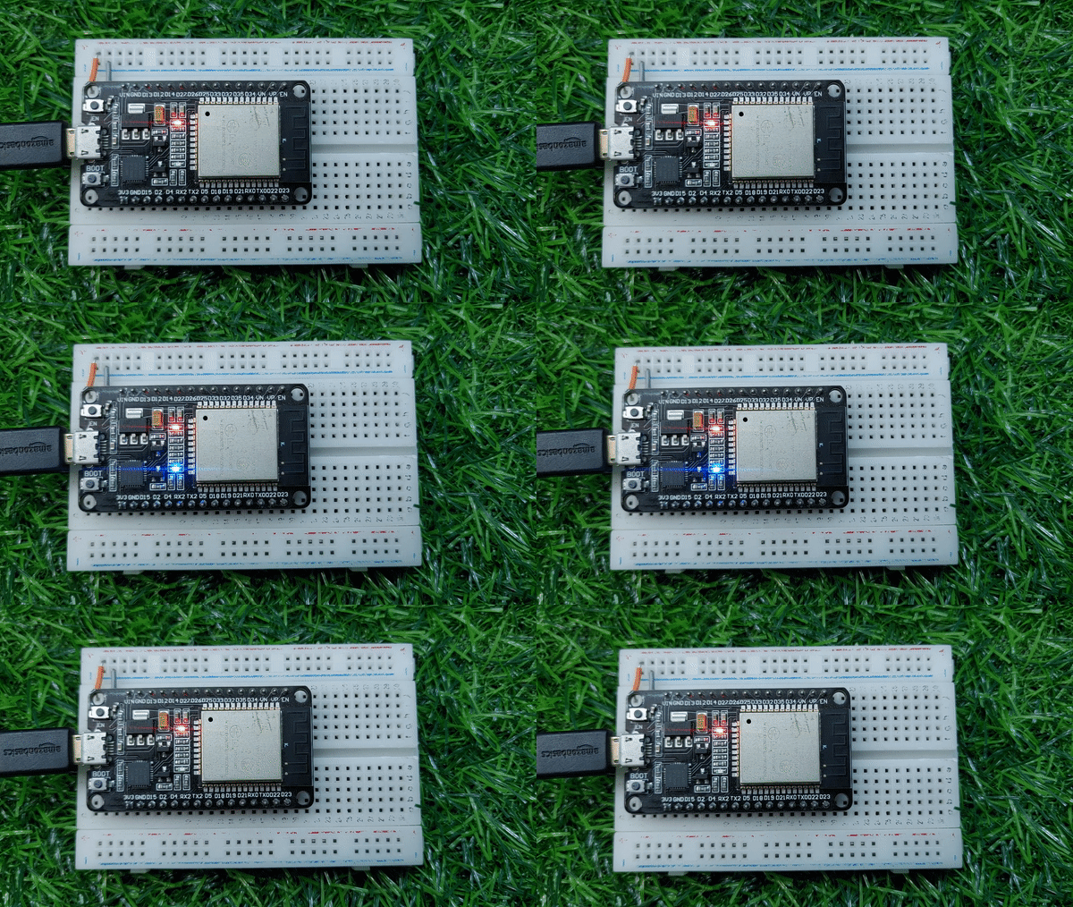
if everything is correct then the onboard led of your esp32 will blink as mine is.
Did you like this post? So leave your comment, question or suggestion below!
Thank you and see you next time!

