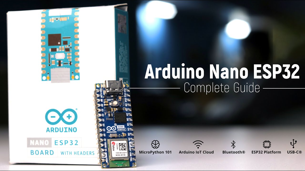
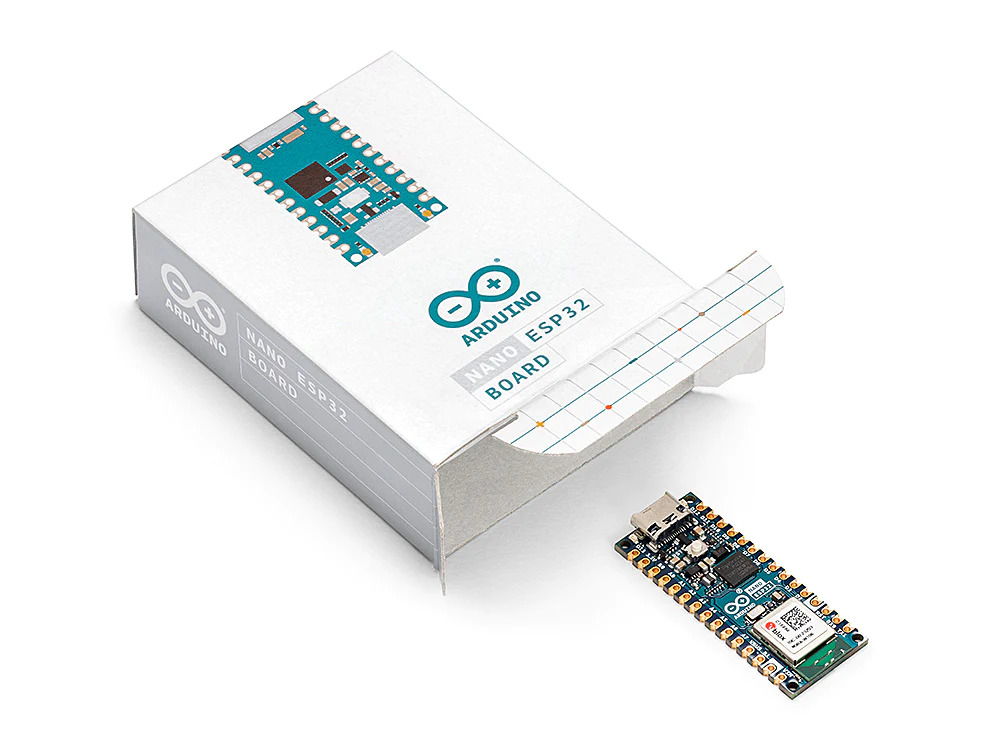
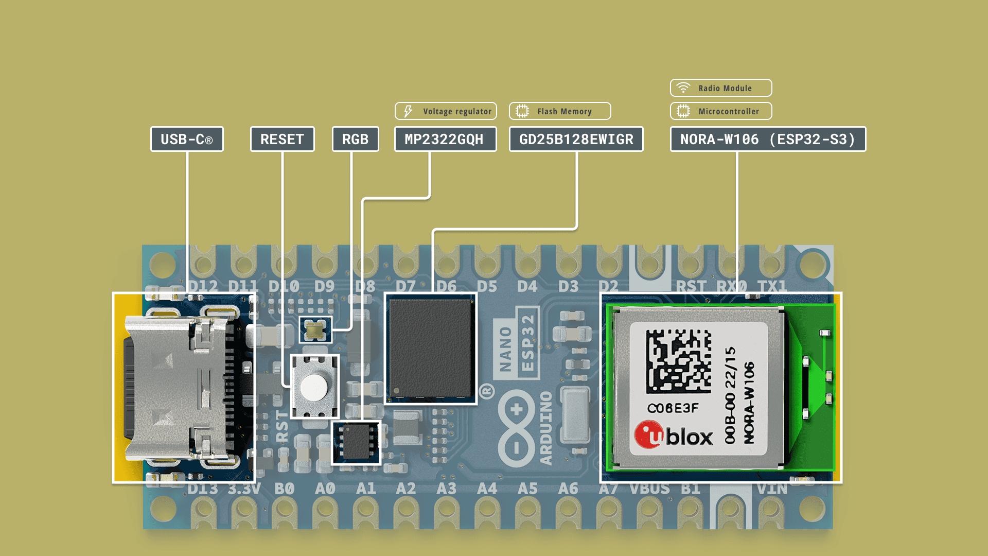
The Arduino Nano ESP32 is a powerful combination of Arduino’s user-friendly features and ESP WROOM32 WIFI + BLE Module from Espressif capabilities. Designed to fit into the Nano family’s compact and practical shape, it is perfect for IoT Projects. It’s a small, simple board that works with the latest ESP-WROOM-32 module, the NORA-W106 module from u-blox®. USB-C connector, 16 MB (128 Mbit) of Flash Memory, support for MicroPython & Arduino IoT Cloud enabled, it is a very adaptable development board.
You can easily plug it into a breadboard. The board has everything needed for the ESP-WROOM-32 to work, including buttons, a USB connection, and a regulator. It also provides access to important GPIO pins for developers.
Thank You NextPCB:
Thanks to the support and sponsorship from NextPCB, Guys if you have a PCB project, I would like to recommend NextPCB for all your PCBs. Be sure to see their website for exciting discounts, coupons, and more
.NextPCB offers high-quality, reliable PCB starting at $1.9, and multilayer starting at $6.9. Also, everyone can enjoy free PCB assembly for 5 boards!
Introducing Nano ESP32
The Nano ESP32 is a 3.3 V development board built around the u-blox® NORA-W106-10B module, which integrates an ESP32-S3 system on a chip (SoC). This module offers Wi-Fi® and Bluetooth® Low Energy (LE) support, featuring enhanced communication via a built-in antenna. The CPU (32-bit Xtensa® LX7) is capable of clock frequencies up to 240 MHz.
Other features of the Nano ESP32 include
Microprocessor:
- Dual-core 32-bit LX7 Xtensa® Microprocessor
- Operating at up to 240 MHz
- 384 kB ROM
- 512 kB low SRAM
- 16 kB low SRAM in RTC (power mode)
- DMA Controller
Power:
- Operating voltage of 3.3 V
- VUSB supplies 5 V via USB-C® connector
- Low VIN range from 6 to 21 V
Connectivity:
- Wi-Fi®
- Bluetooth® LE
- Built-in low antenna
- Low transmitter/receiver at 2.4 GHz
- Up to 150 Mbps
Pins:
- 14x low digital pins (including 21x analog)
- 8x low analog pins (RTC mode)
- Communication via low SPI (D11, D12, D13), I2C (A4/A5), UART (D0/D1)
Communication Protocol
- Low SPI
- Low I2C
- Low I2S
- Low UART
- CAN (TWAI®)
Low Power:
- Low consumption of 7 μA in deep sleep mode
- Low consumption of 240 μA in light sleep mode
RTC Memory:
- Ultra Low Power (ULP) Coprocessor
Power Management Unit (PMU):
- RTC mode low ADC
Technical Specifications of Nano ESP32
| Feature | Specification |
|---|---|
| Board Name | Arduino® Nano ESP32 |
| Microcontroller | u-blox® NORA-W106 (ESP32-S3) |
| USB Connector | USB-C® |
| Pins | Built-in LED Pin: 13 |
| Built-in RGB LED pins: 14-16 | |
| Digital I/O Pins: 14 | |
| Analog Input Pins: 8 | |
| PWM Pins: 5 | |
| External Interrupts: All Digital Pins | |
| Connectivity | Wi-Fi®: u-blox® NORA-W106 (ESP32-S3) |
| Bluetooth®: u-blox® NORA-W106 (ESP32-S3) | |
| Communication | UART: 2x |
| I2C: 1x (A4 – SDA, A5 – SCL) | |
| SPI: D11 (COPI), D12 (CIPO), D13 (SCK). | |
| Use any GPIO for Chip Select (CS) | |
| Power | I/O Voltage: 3.3 V |
| Input Voltage (Nominal): 6-21 V | |
| Source Current per I/O Pin: 40 mA | |
| Sink Current per I/O Pin: 28 mA | |
| Clock Speed | Processor: Up to 240 MHz |
| Memory | ROM: 384 kB |
| SRAM: 512 kB | |
| External Flash: 128 Mbit (16 MB) | |
| Dimensions | Width: 18 mm |
| Length: 45 mm |
Note: Arduino Nano ESP32 works at 3.3 V. So, it’s important not to use more than 3.3 V when connecting to its Digital and Analog pins. it lacks a 5V pin and uses a VBUS pin for 5V when powered via USB. Using VIN won’t give 5V. To connect 5V devices, ,you can optional to use a logic level translator.
Download the Arduino Nano ESP32 Board Datasheet
Block Diagram Of Nano ESP32 Development Board
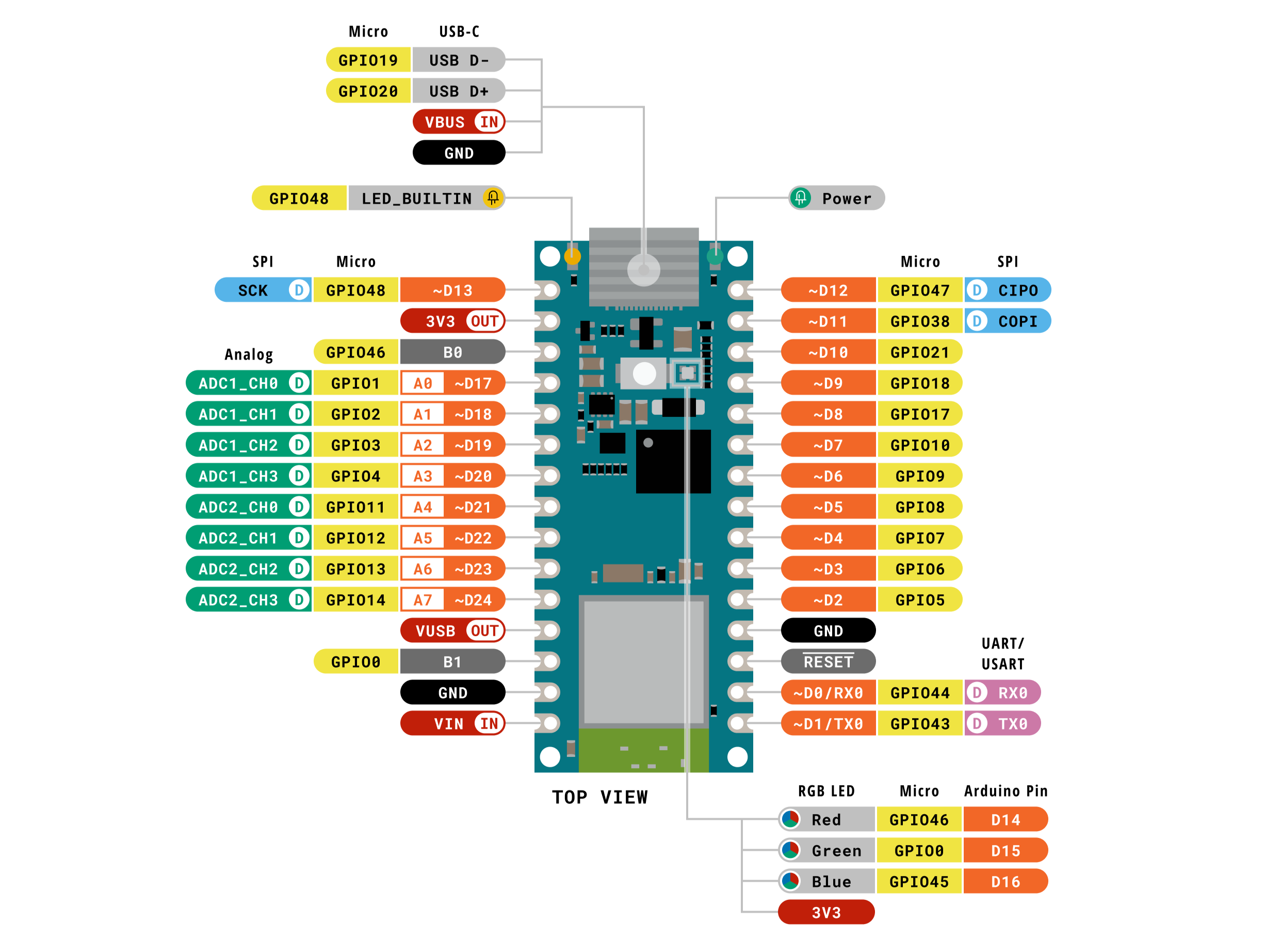
Pinout of Nano ESP32 Development Board
Analog (JP1):
| Pin | Function | Type | Description |
|---|---|---|---|
| 1 | SCK | NC | Serial Clock |
| 2 | +3V3 | Power | +3V3 Power Rail |
| 3 | BOOT0 | Mode | Board Reset 0 |
| 4 | A0 | Analog | Analog input 0 |
| 5 | A1 | Analog | Analog input 1 |
| 6 | A2 | Analog | Analog input 2 |
| 7 | A3 | Analog | Analog input 3 |
| 8 | A4 | Analog | Analog input 4 / I²C Serial Data (SDA) |
| 9 | A5 | Analog | Analog input 5 / I²C Serial Clock (SCL) |
| 10 | A6 | Analog | Analog input 6 |
| 11 | A7 | Analog | Analog input 7 |
| 12 | VUSB | Power | USB power (5V) |
| 13 | BOOT1 | Mode | Board Reset 1 |
| 14 | GND | Power | Ground |
| 15 | VIN | Power | Voltage Input |
Digital (JP2):
| Pin | Function | Type | Description |
|---|---|---|---|
| 1 | D12 / CIPO* | Digital | Controller In Peripheral Out |
| 2 | D11 / COPI* | Digital | Controller Out Peripheral In |
| 3 | D10 | Digital | Chip Select |
| 4 | D9 | Digital | GPIO 9 |
| 5 | D8 | Digital | GPIO 8 |
| 6 | D7 | Digital | GPIO 7 |
| 7 | D6 | Digital | GPIO 6 |
| 8 | D5 | Digital | GPIO 5 |
| 9 | D4 | Digital | GPIO 4 |
| 10 | D3 | Digital | GPIO 3 |
| 11 | D2 | Digital | GPIO 2 |
| 12 | GND | Power | Ground |
| 13 | RST | Internal | Reset |
| 14 | D1/RX | Digital | GPIO 4 / Serial 0 Receiver (RX) |
| 15 | D0/TX | Digital | GPIO 3 / Serial 0 Transmitter (TX) |
Note: “NC” indicates “Not Connected” and * indicates alternate function names.
Getting Started with Nano ESP32
The Nano ESP32 can be programmed using many different programming environments. Code can be written in C++ (like Arduino) or in MicroPython.
For beginners, the best way to get started is by using the familiar Arduino IDE. While this is not necessarily the best environment for working with the ESP32, it has the advantage of being a familiar application.
Nano ESP32 for Arduino IDE
To install the Arduino IDE, you will need to install the Arduino software. and Open the Arduino IDE.
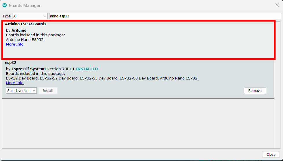
Install Board Package
To install the board package, open the “Board Manager” from the menu to the left. Search for Nano ESP32 and install the latest version.
Blink Code For Nano ESP32
When programming for a new device or using a new development environment, creating a “blink” program is standard.
|
1 2 3 4 5 6 7 8 9 10 11 12 13 14 15 16 17 18 19 20 21 22 23 24 25 26 27 28 29 30 31 32 33 34 35 36 37 |
/* Blink Turns an LED on for one second, then off for one second, repeatedly. Most Arduinos have an on-board LED you can control. On the UNO, MEGA and ZERO it is attached to digital pin 13, on MKR1000 on pin 6. LED_BUILTIN is set to the correct LED pin independent of which board is used. If you want to know what pin the on-board LED is connected to on your Arduino model, check the Technical Specs of your board at: https://www.arduino.cc/en/Main/Products modified 8 May 2014 by Scott Fitzgerald modified 2 Sep 2016 by Arturo Guadalupi modified 8 Sep 2016 by Colby Newman This example code is in the public domain. https://www.arduino.cc/en/Tutorial/BuiltInExamples/Blink */ // the setup function runs once when you press reset or power the board void setup() { // initialize digital pin LED_BUILTIN as an output. pinMode(LED_BUILTIN, OUTPUT); } // the loop function runs over and over again forever void loop() { digitalWrite(LED_BUILTIN, HIGH); // turn the LED on (HIGH is the voltage level) delay(1000); // wait for a second digitalWrite(LED_BUILTIN, LOW); // turn the LED off by making the voltage LOW delay(1000); // wait for a second } |

