This guide will show you how to get started with your Arduino UNO R4 Minima. We’ll cover everything you need to know to get started, including how to connect your Arduino to your computer, how to write sketches, and how to upload your sketches to your Arduino.
it is used by a wide range of people, from hobby applications such as electronic work to IoT and industrial applications. For many creators, the Arduino series is the first microcomputer board they experienced.
The purpose of the “Getting Started with Your Arduino UNO R4 Minima” article is to make it easy for newbies to start their journey with this microcontroller by showing step-by-step instructions, explanations, and resources in a beginner-friendly way. Buy Electronic Components From Ersa Electronics.
Our project reached successful completion thanks to the beneficial help of NextPCB. If you’re working on a PCB project, we highly recommend you visit their website to take advantage of some fantastic discounts and coupons.
NextPCB offers high-quality, reliable PCB starting at $1.9, and multilayer starting at $6.9. Also, everyone can enjoy free PCB assembly for 5 boards!
Compression Arduino UNO R3 With Arduino Uno R4 Minima
Here’s a comparison between the Arduino UNO R3 and the Arduino Uno R4 Minima in a simplified tabular format:
| Feature | Arduino UNO R3 | Arduino Uno R4 Minima |
|---|---|---|
| CPU Manufacturer | AVR® ATmega | Renesas Electronics America Inc. |
| Operating Clock | 16MHz | 48MHz |
| Program Memory | 32KB | 256KB |
| Data RAM | 2KB | 32KB |
| Data ROM | 1KB | 8KB |
Operating clock = calculation speed has tripled
In the R4 version, the key modification is the CPU, which turns from an AVR microcontroller in the R3 to a Renesas microcontroller. This results in a higher operating clock of 48MHz, improved memory with 256KB of program memory, 32KB of data RAM, and 8KB of data ROM.
What’s the Arduino UNO R4 Minima?
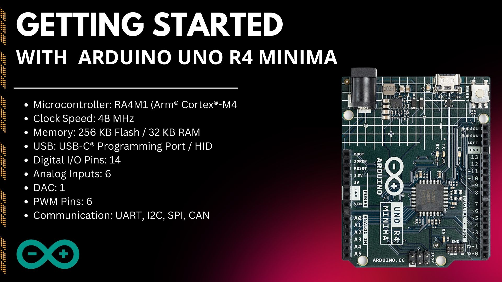
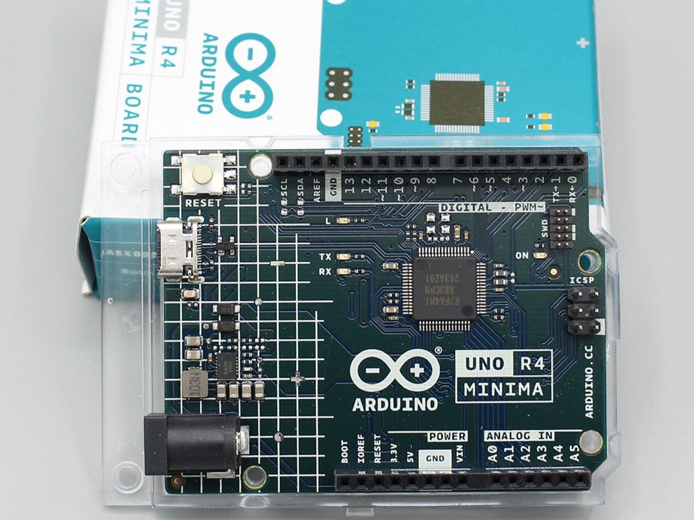
The Arduino Uno R4 Minima is a genuine Arduino board that comes with a powerful 32-bit Renesas RA4M1 ARM Cortex M4 microcontroller chip. It has 256 kB of Flash memory and 32 kB of SRAM memory, which means it can store and process data effectively. You’ll find 14 digital input/output pins, including 6 for pulse-width modulation (PWM), 6 for analog-to-digital conversion (ADC), and 1 for digital-to-analog conversion (DAC), making it versatile for different types of applications. It supports popular communication interfaces like SPI, I2C, UART, and CAN. The module operates at 5V, and you can program it via a USB Type-C connector. It also includes SWD debug pins for debugging and troubleshooting.
The Uno R4 MINIMA also comes with a collection of integrated peripherals, such as a 12-bit DAC, CAN BUS, and OP AMP, delivering users more significant versatility in their innovations.
Additionally, the board supports an extended input voltage range adapting power supplies of up to 24V. This adaptability simplifies the integration with devices like motors, LEDs, and other actuators by using a suitable power source.
A special extra is the board’s inherent Human Interface Device (HID) support, which allows it to emulate a mouse or keyboard when tethered to a computer through USB.
Features Of Arduino UNO R4 Minima
- Microprocessor:
- 48 MHz Arm Cortex-M4 with a floating-point unit (FPU).
- Power:
- Operating voltage: 5V.
- Input voltage (VIN): Recommended range of 6-24V.
- Power source: USB-C at 5V.
- Protection: Schottky diodes for overvoltage and reverse polarity protection.
- Connection: Barrel jack linked directly to the VIN pin.
- Memory:
- Flash memory: 256 kB.
- SRAM: 32 kB.
- Data memory (EEPROM): 8 kB.
- Pins:
- 14 digital GPIO pins labeled D0-D13.
- 6 analog input pins labeled A0-A5.
- 6 PWM pins.
- Peripherals:
- Capacitive Touch Sensing Unit (CTSU).
- USB 2.0 Full-Speed Module (USBFS).
- ADC with up to 14-bit resolution.
- DAC with up to 12-bit resolution.
- Operational Amplifier (OPAMP).
- Communication:
- UART on pins D0 and D1.
- SPI on pins D10-D13 and ICSP header.
- I2C on pins A4, A5, SDA, and SCL.
- CAN on pins D4 and D5, with an external transceiver required.
- Special Features:
- Real-time Clock (RTC) for precise timekeeping.
- Memory Protection Unit (MPU) for enhanced memory security.
- Digital Analog Converter (DAC) for precise analog operations.
Arduino UNO R4 Minima Circuit Diagram
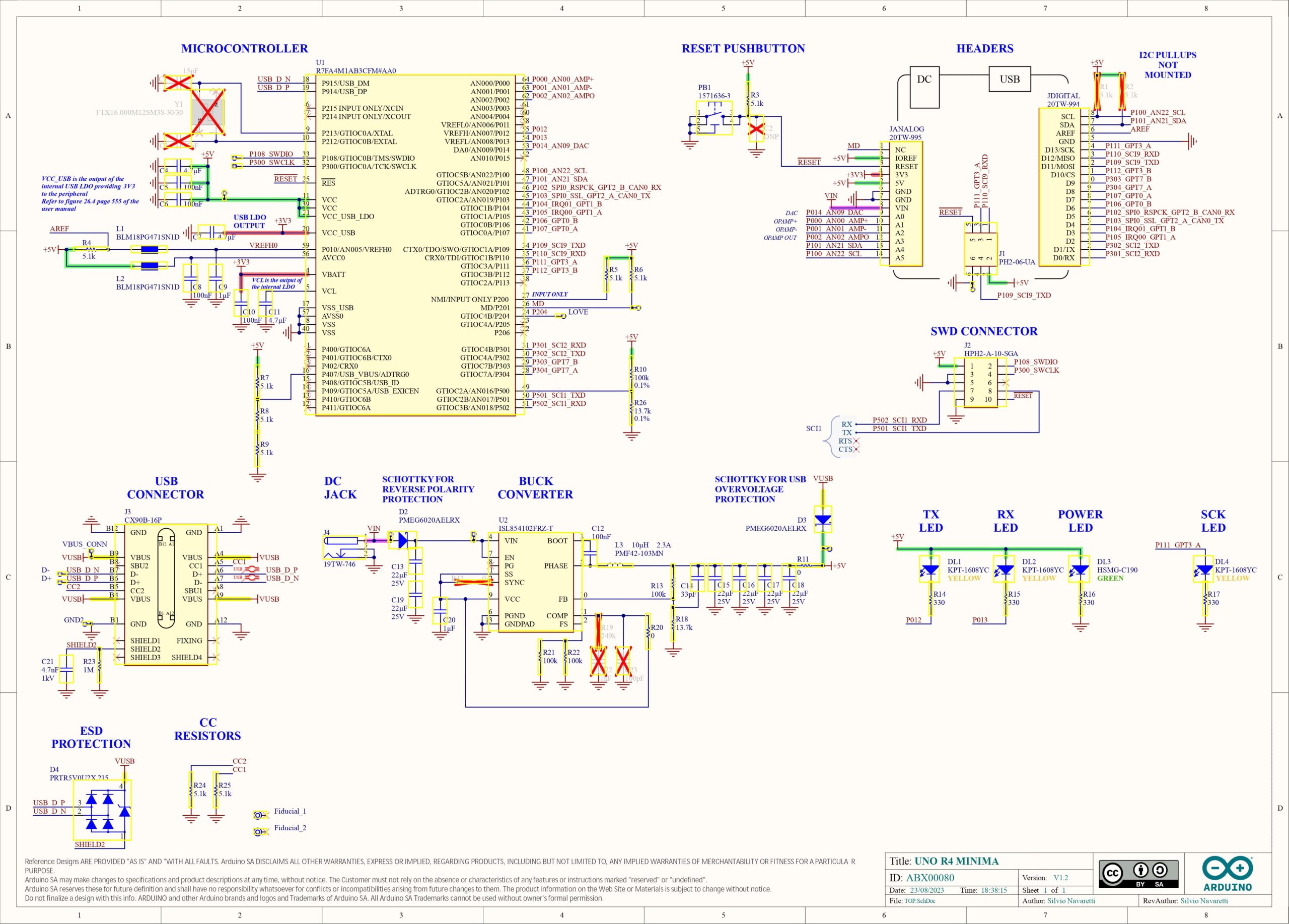
Now, let’s take a look at R4’s circuit diagram.
R4 uses a switching regulator in its power supply IC. There’s also a Schottky barrier diode between the DC jack and the power supply IC to control damage in case the power is accidentally connected the wrong way.
The switching regulator IC, also made by Renesas, can take an input voltage of up to 24V, which it steps down to the 5V required by the microcontroller. According to the regulator’s datasheet, it can handle inputs up to 40V, but using it above 24V isn’t recommended.
In difference, R3 used a linear regulator with the highest input voltage of 20V, and its minor voltage was 12V.
The difference in input voltage tolerance indicates that R4 is developed for industrial use, aligning with the 24V generally used in industrial settings.
About the USB input, R4 is marked with “ESD Protection,” meaning it has a diode for electrostatic protection. R3, on the other hand, had only two varistors, offering extra attention to power stability in R4.
In R3, the linear regulator is quiet but highly ineffective, with only about 40% efficiency when converting 12V to 5V.
In difference, R4 uses a switching regulator, offering much higher efficiency, going from 70% to 90% according to the datasheet. This change prioritizes efficiency over lower noise levels.
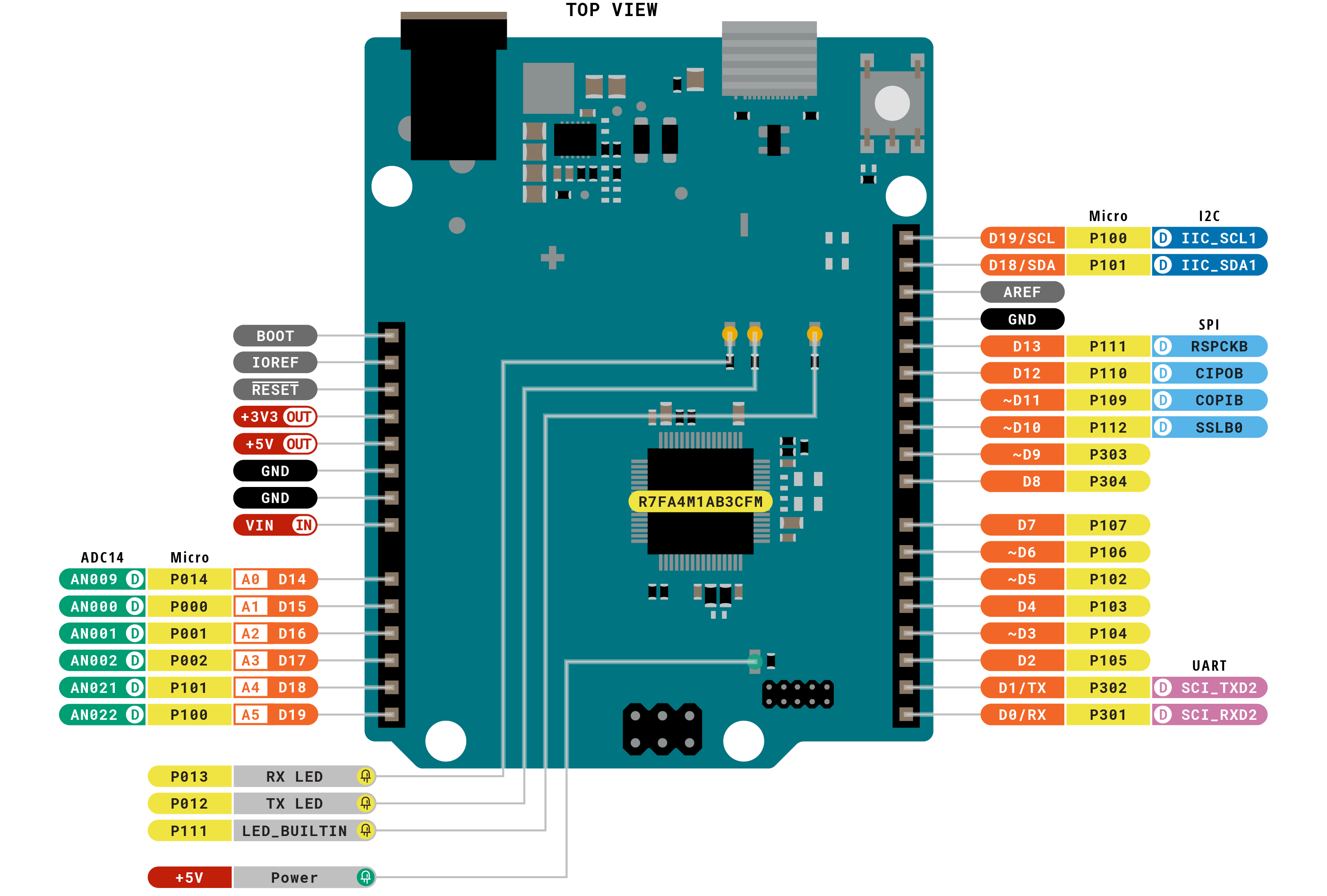
Arduino UNO R4 Minima Pinout
Power Pins
- VIN: Input – Accepts voltage input in the range of 6V to 24V.
- +3V3: Output – Provides a 3.3V power rail.
- +5V: Output – Supplies a 5V power rail.
- GND: Ground – Serves as the ground reference.
- IOREF: Output – Outputs a reference voltage of 5V.
Digital GPIO Pins
- D0-D13: General-purpose digital pins.
- D3, D5, D6, D9, D10, D11: PWM – Used for Pulse Width Modulation.
- D1/TX0, D0/RX0: UART – Facilitates Serial Communication.
- D13/SCK, D12/CIPO, D11/COPI, D10/CS: SPI – Enables Serial Peripheral Interface.
- D5/CANRX0, D4/CANTX0: CAN – Supports CAN Bus Communication.
Analog Pins
- A0-A5: Input – Serve as analog input pins.
- A0: DAC – Functions as a Digital to Analog Converter.
- A1, A2: OPAMP – Provides operational amplifier capabilities.
- A4, A5: I²C – Enables I²C Communication (SDA and SCL).
Other Pins
- BOOT: Mode – Used for mode selection.
- Reset: – Performs a board reset.
- AREF: Input – Accepts analog reference voltage.
Operating Conditions & Power Supply
- VIN: Input voltage from VIN pad / DC Jack
- Minimum: 6V
- Typical: 7.0V
- Maximum: 24V
- VUSB: Input voltage from USB connector
- Minimum: 4.8V
- Typical: 5.0V
- Maximum: 5.5V
- TOP: Operating Temperature
- Minimum: -40°C
- Typical: 25°C
- Maximum: 85°C
Getting started with your Arduino UNO R4 Minima
Set up your Arduino IDE for Minima boards by installing the necessary board manager. Whether you’re using Arduino IDE Version 2 or the classic 1.8, the process is the same on Windows, macOS, or Linux.
Open the IDE, access Boards Manager, search for ‘uno’, and install the board manager provided by Arduino. Test the installation by connecting your board and selecting the correct port.
Download and Install Arduino IDE
Download and install Arduino IDE for Arduino project development. Visit the Arduino official page, and choose your OS version.
Install the IDE, and it will automatically configure the necessary components.
Installing Arduino UNO R4 Minima Board In Arduino 1.8 IDE
Installing the Arduino UNO R4 Minima Board in Arduino 1.8 IDE is an easy process. Follow the below steps to get it done:
- Launch your Arduino IDE and navigate to ‘Preferences.’
- Click on the ‘Additional Board Manager URL‘ button.
- Add the Arduino R4 Renesas URL according to your operating system:
Your Arduino IDE is now ready to go……..
Example one — LED blinking
To get started, let’s write a basic LED blink code using the Arduino IDE.
|
1 2 3 4 5 6 7 8 9 10 |
void setup() { pinMode(13, OUTPUT); } void loop() { digitalWrite(13, HIGH); delay(100); digitalWrite(13, LOW); delay(100); } |
Click ‘Upload‘ to load the code onto your UNO R4 Minima. Once uploaded, the onboard LED at Pin 13 blinks every second.
Adjust the ‘delay’ parameter to change the blinking interval for experimentation

