Overview
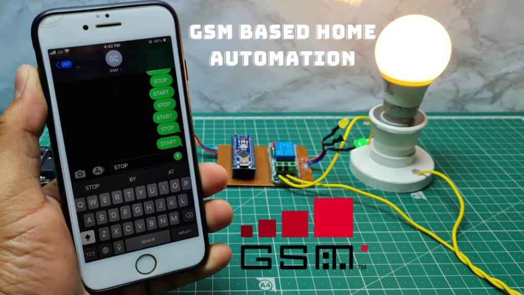
hey friend’s welcome in “DiY Projects Lab” In this project you’re going to build an GSM Home Automation System using arduino. where we can control the home appliances (T.V. , BULB), using the simple GSM based phone, just by sending SMS through the phone. In this Home Automantion System Project, no Smart phone is needed just the any old GSM phone you can control any home electronic appliances, from anywhere anytime .
GSM Home Automation Working Explanation
The brain of this project is an Arduino nano board which in combination with GSM module . GSM wireless communication for controlling electronics home appliances , We send some commands like “#A.Start*”, “#A.stop *” After receiving given commands by the Arduino through GSM module then Arduino send signal to relays for cut ON or OFF.
Components For GSM Based Home Automation System Using Arduino
You can get the components for Home automantion from the links below
- Arduino nano x1
- GSM module x1
- Relay Module x1
- Conneting wire and LED
- Bulb
- Holder
When you send SMS to GSM module by phone , then GSM receives that SMS and sends it to Arduino. then Arduino compare this command with predefined command .if it match with predefined command then then Arduino sends data to relay via relay for turning ON and OFF home appliances .
Here in this project we have used 1 zero watt bulb .
| S.no. | Message | Operation |
| 1 | #A.Start* | Bulb ON |
| 2 | #A.Stop* | Bulb OFF |
GSM Module
GSM module (Global System for Mobile Communications) SIM900A Model is built with Dual Band GSM/GPRS based used in many communication devices which are based on GSM technology.
There are various AT Commands like ATD to dial a call , ATA for answer a call, AT+CMGS to send the sms ,AT+CMGR to read the message etc.
We can use GSM module using these commands for any GSM Projects
Basic AT Command
1. To change sms sending mode : AT+CMGF=1
|
1 |
mySerial.println("AT+CMGF=1"); |
2. To read SMS in text mode : AT+CNMI=2,2,0,0,0
|
1 |
mySerial.println("AT+CNMI=2,2,0,0,0"); |
3. To make a call : ATD+916209403151; //replace X with number you want to call, change +60 to your country code
|
1 |
mySerial.println("ATD+916209403151;"); |
4. To disconnect / hangup call : ATH
|
1 |
mySerial.println("ATH"); |
5. To redial : ATDL
|
1 |
mySerial.println("ATDL"); |
6. To receive a phone call : ATA
|
1 |
mySerial.println("ATA"); |
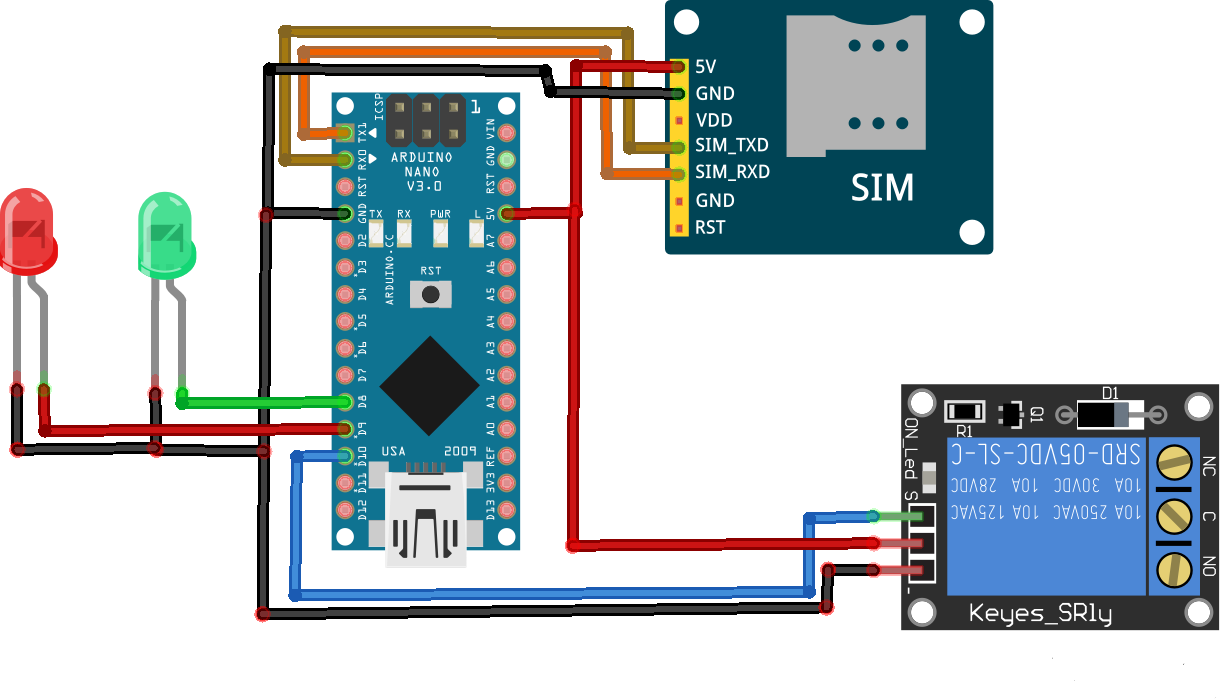
GSM Based Home Automation System Using Arduino Circuit Diagram :
Connections:
GSM Sim900A :
- GSM Rx to Arduino Tx.
- GSM Tx to Arduino Rx.
- 5v to external 5v supply which can deliver up to 1 amp.
- Ground to ground.
Relay :
- VCC to 5V
- GND to GND
- Relay to D1
Programming
CODE for GSM Based Home Automantion System
|
1 2 3 4 5 6 7 8 9 10 11 12 13 14 15 16 17 18 19 20 21 22 23 24 25 26 27 28 29 30 31 32 33 34 35 36 37 38 39 40 41 42 43 44 45 46 47 48 49 50 51 52 53 54 55 56 57 58 59 60 61 62 63 64 65 66 67 68 |
#include <SoftwareSerial.h> // Library for using serial communication SoftwareSerial SIM900(7, 8); // Pins 7, 8 are used as used as software serial pins String incomingData; String message = ""; int relay_pin = 1; // Initialized a pin for relay module void setup() { Serial.begin(115200); // baudrate SIM900.begin(19200); // baudrate for GSM pinMode(relay_pin, OUTPUT); digitalWrite(relay_pin, HIGH); SIM900.print("AT+CMGF=1\r"); delay(100); SIM900.print("AT+CNMI=2,2,0,0,0\r"); delay(100); } void loop() { //Function for receiving sms receive_message(); // if received command is to turn on relay if(incomingData.indexOf("Start")>=0) { digitalWrite(relay_pin, LOW); message = "Led is turned ON"; send_message(message); } // if received command is to turn off relay if(incomingData.indexOf("Stop")>=0) { digitalWrite(relay_pin, HIGH); message = "Led is turned OFF"; send_message(message); } } void receive_message() { if (SIM900.available() > 0) { incomingData = SIM900.readString(); Serial.print(incomingData); delay(10); } } void send_message(String message) { SIM900.println("AT+CMGF=1"); delay(100); SIM900.println("AT+CMGS=\"+916209403151\""); // Replace it with your number delay(100); SIM900.println(message); delay(100); SIM900.println((char)26); delay(100); SIM900.println(); delay(1000); } |


1 Comment
Pingback: Make Arduino Home automation System Using TV Remote