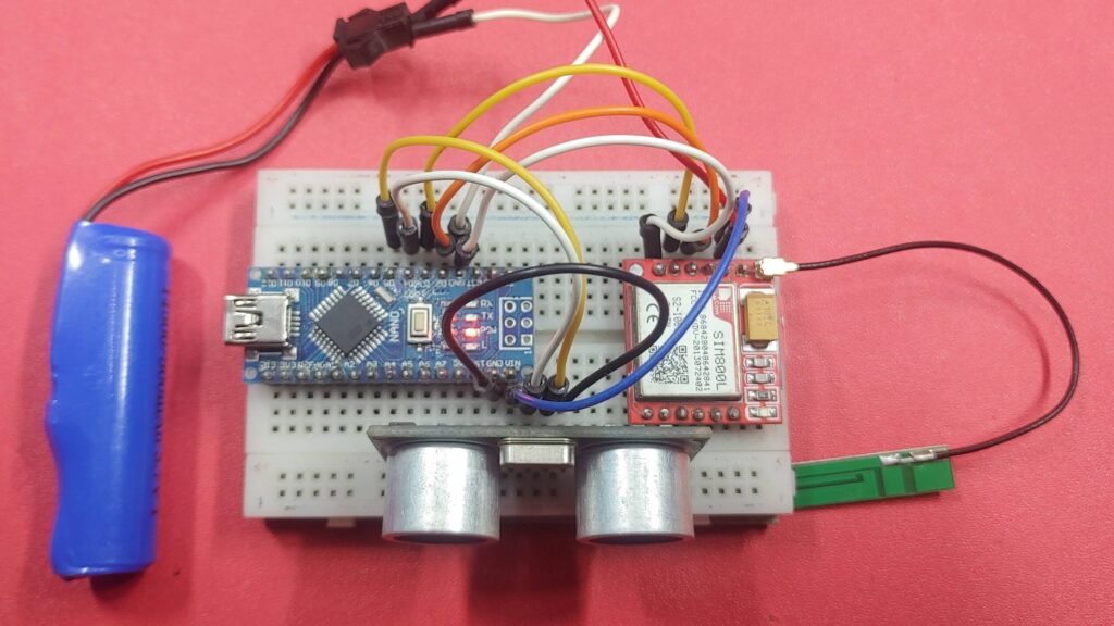
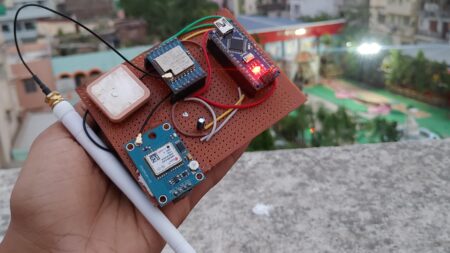
GSM-based home security systems with ultrasonic sensors to detect movements. When the ultrasonic sensor detects a change in distance, an alarm is triggered, and an alert is sent via the SIM800 GSM Module to the user’s mobile device. The system uses an Arduino microcontroller board and SIM800l GSM module for communication.
Required Components
- SIM800l GSM Module
- Arduino nano
- Ultrasonic sensor
- SIM
- Jumper wires
- Breadboard
- Power Supply
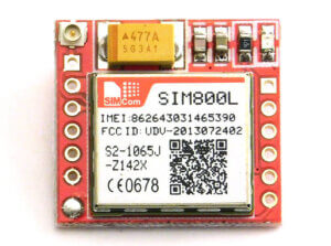
SIM800l GSM Module
The SIM800L GSM module is a mall device that enables communication over the Global System for Mobile Communications (GSM) network. The module provides a means for devices to connect to a mobile network and transmit data, make voice calls, and send text messages.
The module has a SIM card slot, which can accept a SIM card from a GSM network provider. SIM800L GSM module works in a frequency range of 850MHz to 1900MHz, making it compatible with 2G GSM networks globally. It works well with AT commands. Check out the SIM800L Arduino tutorial
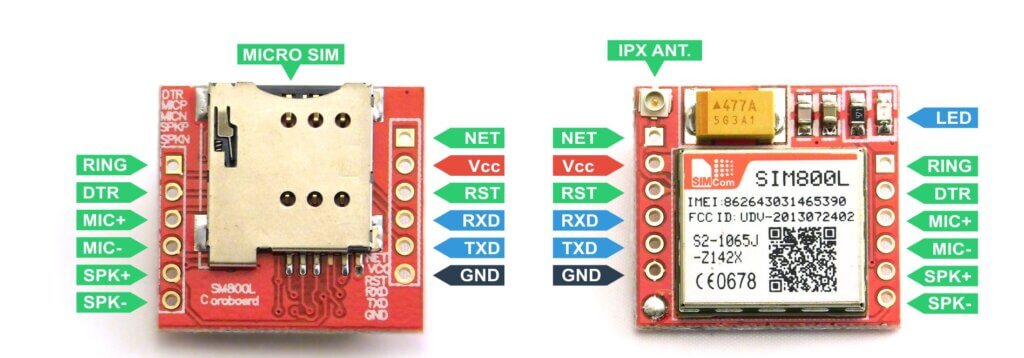
Pinout of SIM800l GSM Module
| PIN | DESCRIPTION |
|---|---|
| RING | Low state when module receives a call |
| DTR | Module Sleep, high state by default, changing to low state module comes out of sleep |
| MICP | Microphone connector (P +) |
| MICN | Microphone connector (N -) |
| SPKP | Headphone connector (P +) |
| SPKN | Headphone connector (N -) |
| NET | Antenna connector |
| VCC | Power supply from 3.8 V to 4.2 V |
| RESET | System reset |
| RXD | Serial communication (receive) |
| TXD | Serial communication (transmit) |
| GND | System ground |
HCSR04 Ultrasonic Sensor
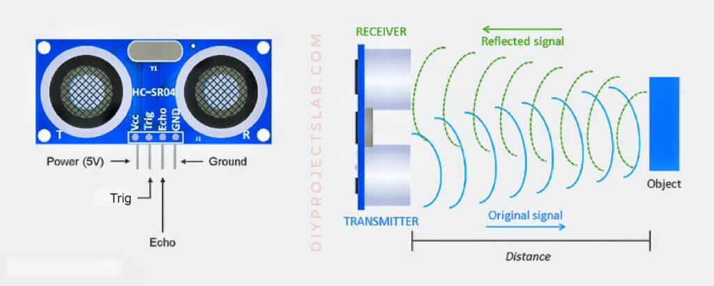
The HCSR04 Ultrasonic Sensor is generally used for measuring distance using ultrasound waves. It is widely used in robotics, automation, and security systems. this sensor uses ultrasound waves to measure the distance to an object. It emits a pulse, waits for the echo, and calculates the distance based on the time it takes for the echo to return. How to use ultrasonic sensor with Arduino tutorial
Pinout of HCSR04 Ultrasonic Sensor
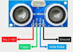
- VCC
- GND
- TRIG
- ECHO
Specifications of HCSR04 Ultrasonic Sensor
- Operating Voltage: 5V DC
- Measuring Range: 2cm to 400cm
- Resolution: 0.3 cm
- Measurement Angle: 15 degrees
- Working Frequency: 40kHz
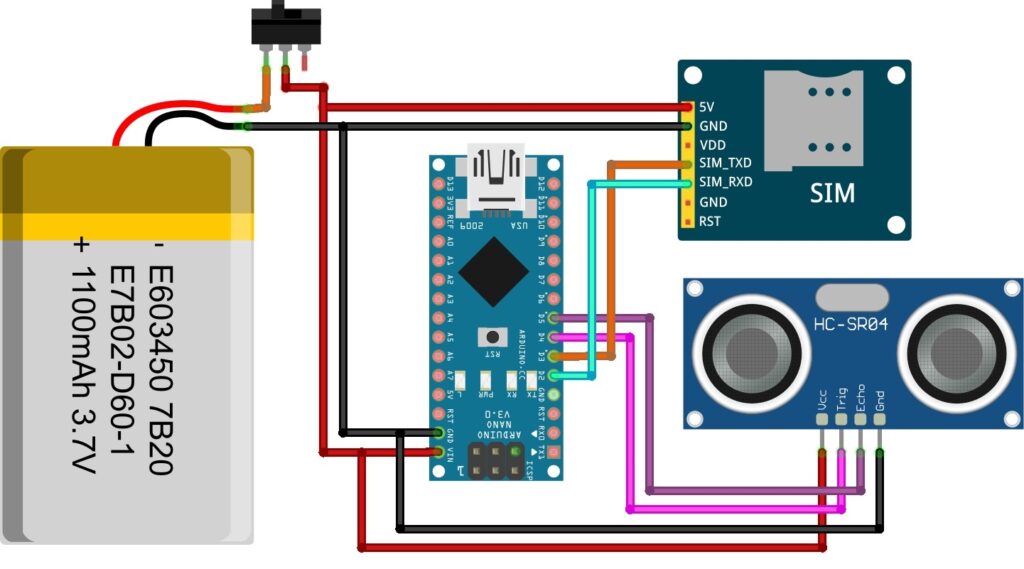
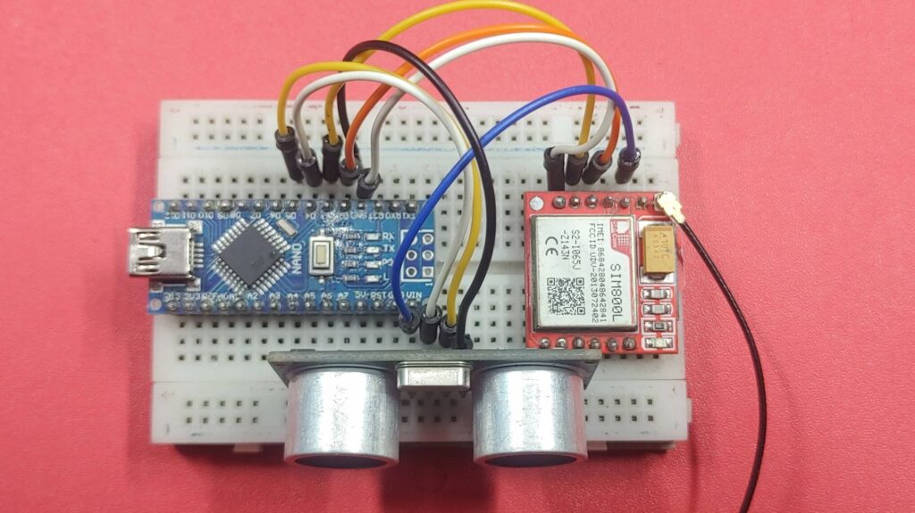
Wiring Diagram – Arduino GSM Home Security System
SIM800L GSM –> Arduino board
- TX pin to Arduino pin 3 (RX).
- RX pin to Arduino pin 2 (TX).
- VCC to Arduino 5V pin
- GND to Arduino GND.
Additionally, provide power to the module by connecting the VCC and GND pins to the appropriate power sources.
Source Code – Arduino Home Security System
Now let’s dive into the code. The code starts by initializing the serial communication between the Arduino and the SIM800L module
|
1 2 3 4 5 6 7 8 9 10 11 12 13 14 15 16 17 18 19 20 21 22 23 24 25 26 27 28 29 30 31 32 33 34 35 36 37 38 39 40 41 42 43 44 45 46 47 48 49 50 51 52 53 54 55 56 57 58 59 60 61 62 63 64 65 66 67 68 69 70 71 72 73 74 75 76 77 78 79 80 81 82 83 84 85 86 87 88 89 90 91 92 93 94 95 96 97 98 99 100 101 102 103 104 105 106 107 108 |
#include <SoftwareSerial.h> // Create software serial object to communicate with SIM800L SoftwareSerial mySerial(3, 2); // SIM800L Tx & Rx is connected to Arduino #3 & #2 #define trigPin 4 #define echoPin 5 #define alarmPin 6 const String PHONE_NUMBER = "+916209403151"; // Replace with recipient number void setup() { pinMode(trigPin, OUTPUT); pinMode(echoPin, INPUT); pinMode(alarmPin, OUTPUT); // Begin serial communication with Arduino and Arduino IDE (Serial Monitor) Serial.begin(9600); // Begin serial communication with Arduino and SIM800L mySerial.begin(9600); Serial.println("Initializing..."); delay(1000); sendATCommand("AT"); // Once the handshake test is successful, it will return OK sendATCommand("AT+CMGF=1"); // Configuring TEXT mode } void loop() { while (mySerial.available()) { Serial.write(mySerial.read()); // Print the response from the module } long time_duration, distance_in_cm; digitalWrite(trigPin, LOW); delayMicroseconds(2); digitalWrite(trigPin, HIGH); delayMicroseconds(10); digitalWrite(trigPin, LOW); time_duration = pulseIn(echoPin, HIGH); distance_in_cm = time_duration / 29 / 2; Serial.print("Distance: "); Serial.print(distance_in_cm); Serial.println(" cm"); if (distance_in_cm <= 10) { Serial.println("Intruder detected!"); activateAlarm(); sendSMS(PHONE_NUMBER, "Intruder detected!"); // Send SMS makeCall(PHONE_NUMBER); // Make a call delay(5000); // Delay to prevent continuous triggering } else { deactivateAlarm(); } delay(500); } void sendATCommand(const String& command) { mySerial.println(command); delay(500); while (mySerial.available()) { Serial.write(mySerial.read()); // Print the response from the module } } void sendSMS(const String& phoneNumber, const String& message) { mySerial.println("AT+CMGS=\"" + phoneNumber + "\""); delay(1000); mySerial.println(message); delay(1000); mySerial.write(26); // Send Ctrl+Z character to indicate the end of the message delay(5000); while (mySerial.available()) { Serial.write(mySerial.read()); // Print the response from the module } } void makeCall(const String& phoneNumber) { mySerial.println("ATD" + phoneNumber + ";"); delay(10000); // Delay for the call to connect (adjust as needed) mySerial.println("ATH"); // Hang up the call } void activateAlarm() { digitalWrite(alarmPin, HIGH); } void deactivateAlarm() { digitalWrite(alarmPin, LOW); } |
Working
Upload the code to your Arduino board and open the serial monitor.
You should see the initialization process and responses from the SIM800L module.
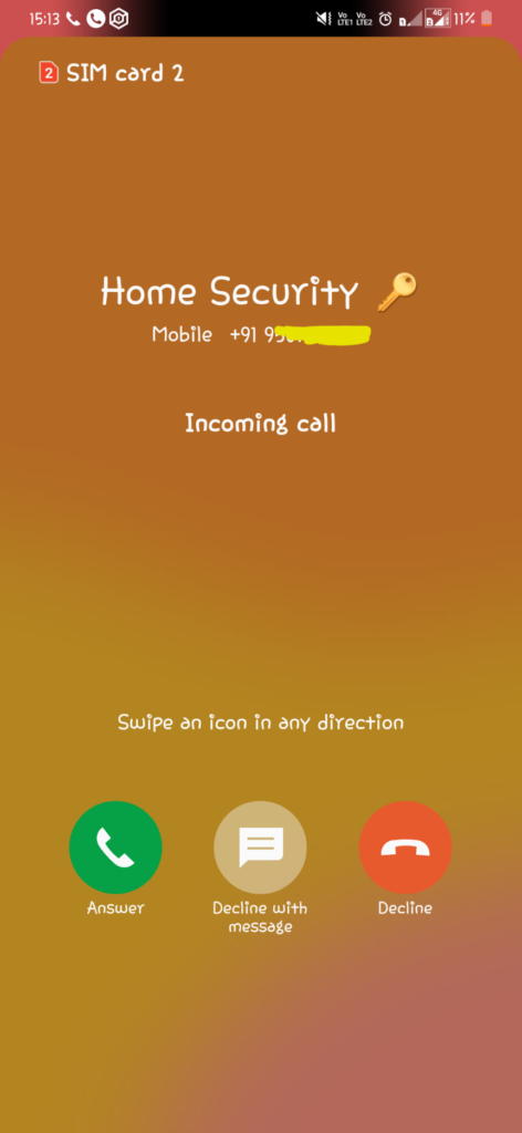
If the distance measured by the HCSR04 Ultrasonic Sensor falls below a given threshold value, it indicates unauthorized movement or Intruder detected the GSM module initiates a CALL notification to the user’s mobile device.
Also, check this

