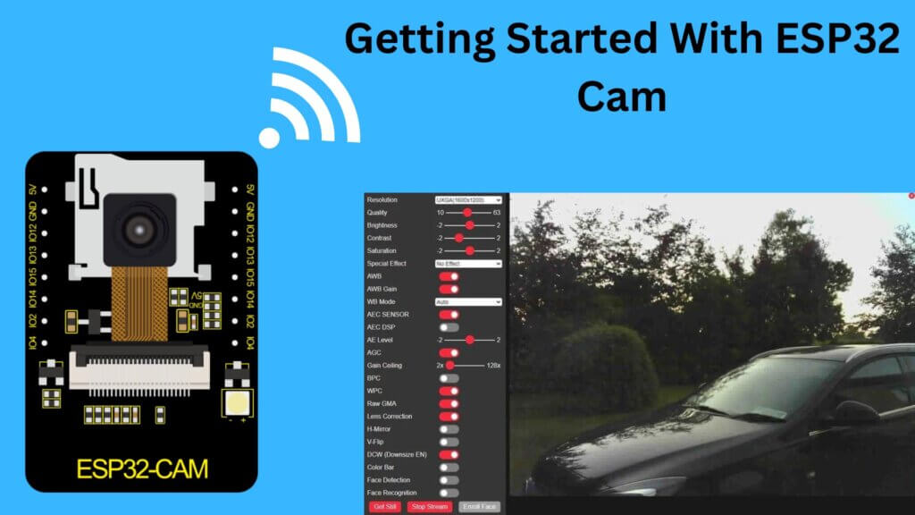
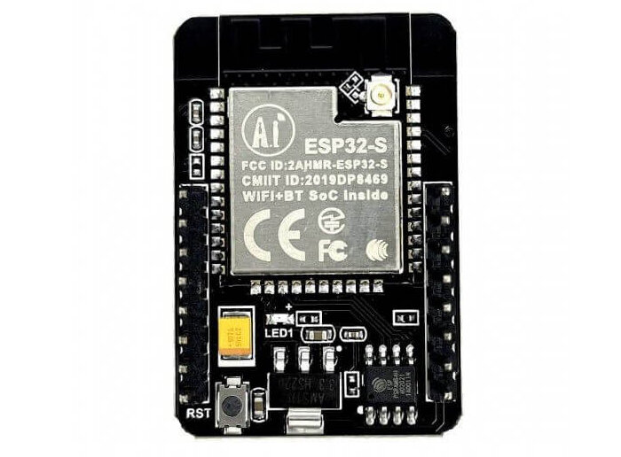
This tutorial provides a guide to using the ESP32 Cam module to create projects. The ESP32 Cam module is a small camera module that can take high-quality pictures or videos. ESP32-CAM is a full-featured microcontroller with an integrated camera and microSD card socket.
It’s inexpensive and easy to use and is perfect for IoT devices, security systems, and drones that require a camera with complex capacities like vision tracking and Face recognition.
Required Material
These are the things that you will need for this built/setup
- Breadboard
- ESP32 CAM
- FTDI Module
- Wires
- WIFI Connection
What is the ESP32 Cam Module?
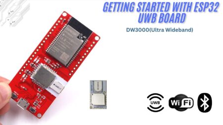
The ESP32-CAM module is a small-size camera module that integrates the ESP32-s chip, it has an OV2640 camera, GPIO pins to connect peripherals like sensors, motors, etc., and a micro SD card slot. It is a low-cost and easy-to-use solution for DIY makers who want to build projects with image or video abilities.
The ESP32-S is a powerful microcontroller with a 32-bit CPU with a clock frequency of up to 240MHz, It has 520 KB of internal SRAM, as well as an external 4 MB PSRAM. also has a built-in 802.11b/g/n Wi-Fi and Bluetooth/BLE SoC module, which makes it easy to connect to the internet and other devices.
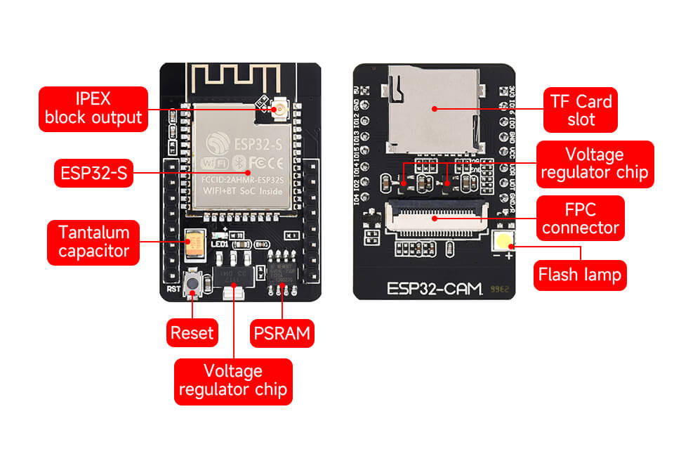
It supports image Wi-Fi upload, which means images captured by the ESP32-CAM can be uploaded instantly to a server or cloud storage service through Wi-Fi connections.
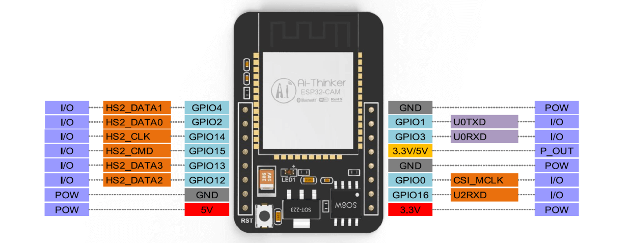
ESP32 Cam Pinout
ESP32-CAM module has several GPIO (General Purpose Input/Output) pins that are used to connect peripherals or sensors.
Features
- Onboard ESP32-S chip, supports WiFi + Bluetooth
- OV2640 camera with a resolution of up to 2 megapixels
- The Onboard SD card slot, supports up to 4GB TF cards for data storage
- Support for Image WiFi Upload
- Embedded Lwip and FreeRTOS
- Low Power Consumption
- Supports multi-sleep modes, deep sleep current as low as 6mA
- ESP32 has several GPIO pins which are used to connect peripherals
Specifications
- WIFI module: ESP-32S
- Processor: ESP32-D0WD
- Built-in Flash: 32Mbit
- RAM: Internal 512KB + External 4M PSRAM
- Antenna: Onboard PCB antenna
- WiFi protocol: IEEE 802.11 b/g/n/e/i
- Bluetooth: Bluetooth 4.2 BR/EDR and BLE
- WIFI mode: Station / SoftAP / SoftAP+Station
- Security: WPA/WPA2/WPA2-Enterprise/WPS
- Output image format: JPEG (OV2640 support only), BMP, GRAYSCALE
- Supported TF card: up to 4G
- Peripheral interface: UART/SPI/I2C/PWM
- IO port: 9
- UART baudrate rate: default 115200bps
- Power supply: 5V
- Transmitting power:
- 802.11b: 17 ±2dBm(@11Mbps)
- 802.11g: 14 ±2dBm(@54Mbps)
- 802.11n: 13 ±2dBm(@HT20,MCS7)
- Receiving sensitivity:
- CCK,1Mbps: -90 dBm
- CCK,11Mbps: -85 dBm
- 6Mbps(1/2 BPSK): -88 dBm
- 54Mbps(3/4 64-QAM): -70 dBm
- HT20,MCS7(65Mbps, 72.2Mbps): -67 dBm
- Power consumption:
- Flash off: 180mA@5V
- Flash on and brightness max: 310mA@5V
- Deep-Sleep: as low as 6mA@5V
- Modern-Sleep: as low as 20mA@5V
- Light-Sleep: as low as 6.7mA@5V
- Operating temperature: -20 ℃ ~ 85 ℃
- Storage environment: -40 ℃ ~ 90 ℃, <90%RH
Applications
- Smart home devices
- Wireless monitoring
- Intelligent farming
- QR wireless identification
- facial recognition
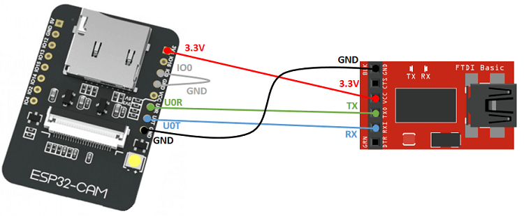
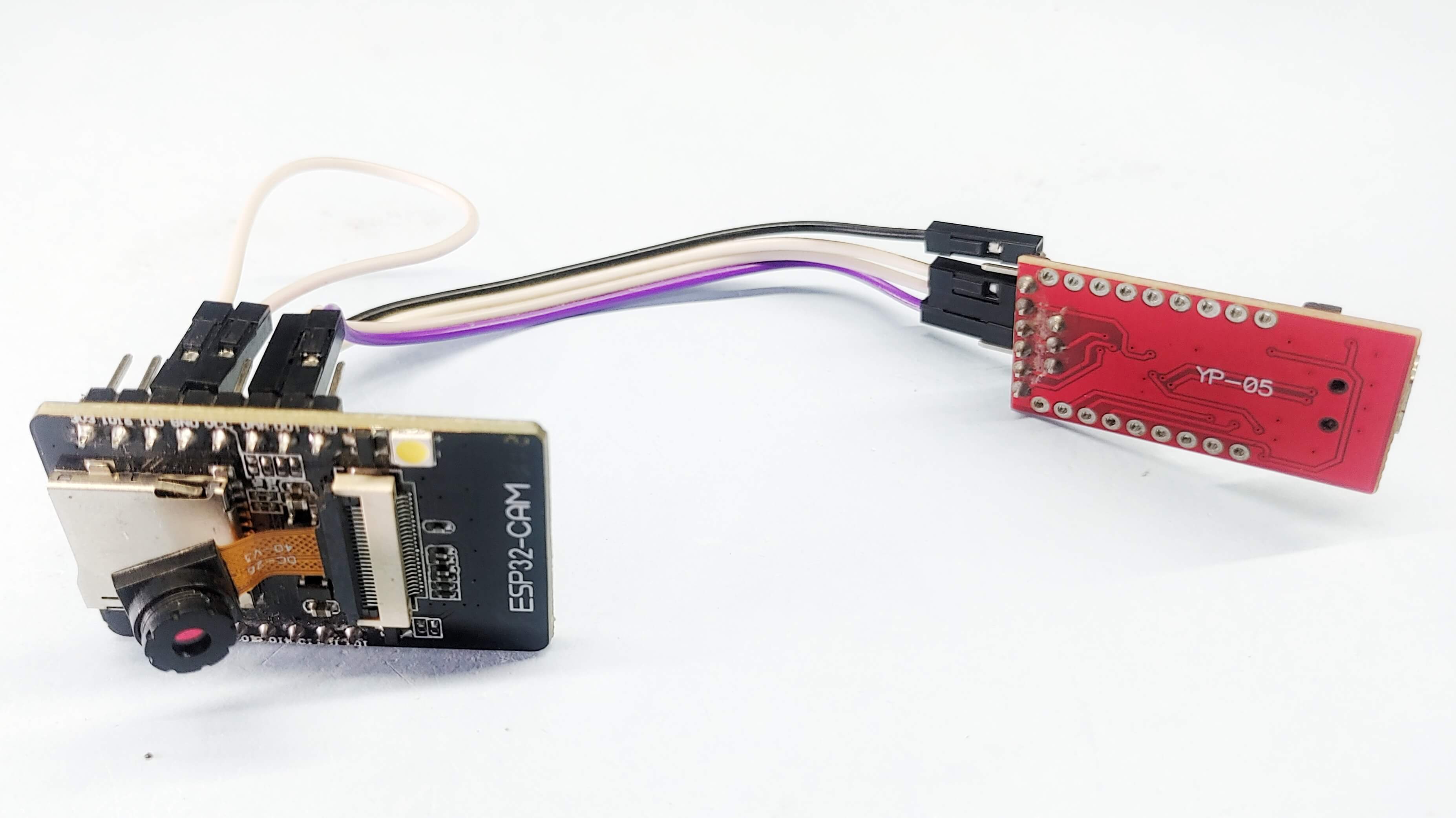
Connection Between ESP32-CAM with FTDI
The ESP32-CAM module can be programmed using an FTDI programmer, which is a USB-to-serial converter. Here’s a show of how you can connect an FTDI programmer to the ESP32 CAM module:
| ESP32-CAM | FTDI PROGRAMMER |
|---|---|
| GND | GND |
| 5V | VCC (5V) |
| U0R | TX |
| U0T | RX |
| GPIO 0 | GND |
Installing ESP32 board package In Arduino IDE
Go to the official Arduino website at https://www.arduino.cc/en/software, Click on the “Download the Arduino IDE” button, and install it.
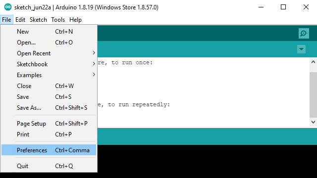
Open the Arduino IDE and click on the “File” menu, then select “Preferences“.
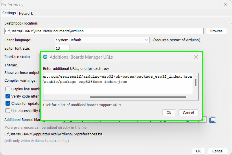
In the “Additional Boards Manager URLs” field, add the following URL: “https://raw.githubusercontent.com/espressif/arduino-esp32/gh-pages/package_esp32_index.json” then click “OK” to save the changes.
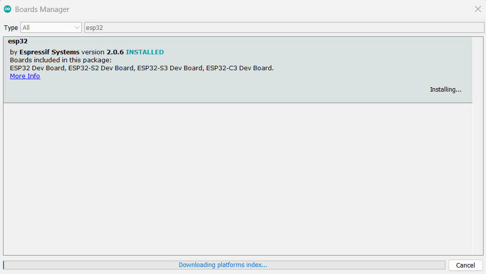
Now click on “Boards Manager” and search for “esp32” in the search bar.
Click on the “esp32 by Espressif Systems” package and click the “Install” button.\
Set up ESP32 CAM Board on Arduino IDE
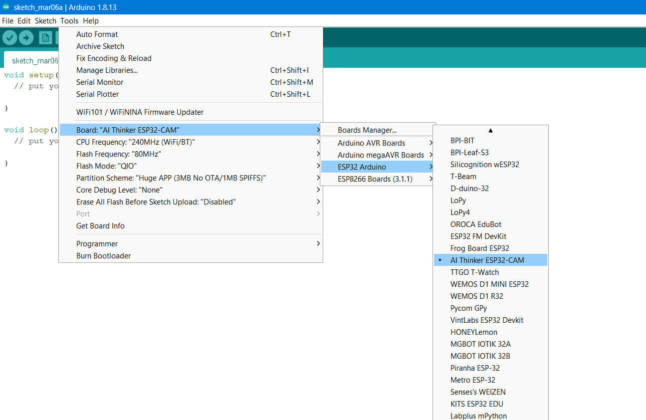
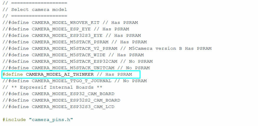
Go to the “Tools” menu and select “Board”. From the list of available boards, select “AI-Thinker ESP32-CAM“.
Connect the FTDI programmer to your computer using a USB cable.
go to the “Tools” menu and select the correct COM port under the “Port” option. You are now ready to start programming the ESP32-CAM board in the Arduino IDE.
Source Code
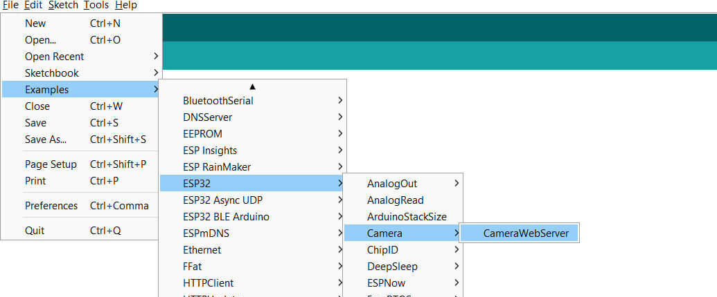
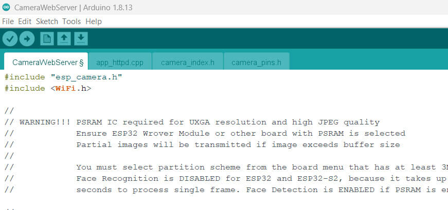
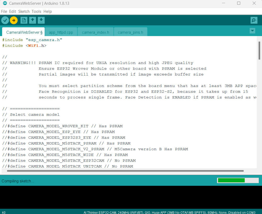
Go to Example> ESP32> Camera and open the CameraWebServer sketch, This will open the “CameraWebServer” example sketch.
Here is an example code for basic video streaming using the ESP32-CAM module:
Configure WiFi
|
1 2 |
const char* ssid = "DIY"; const char* password = "77777777"; |
Upload the file The code will take more than a minute to compile and upload.
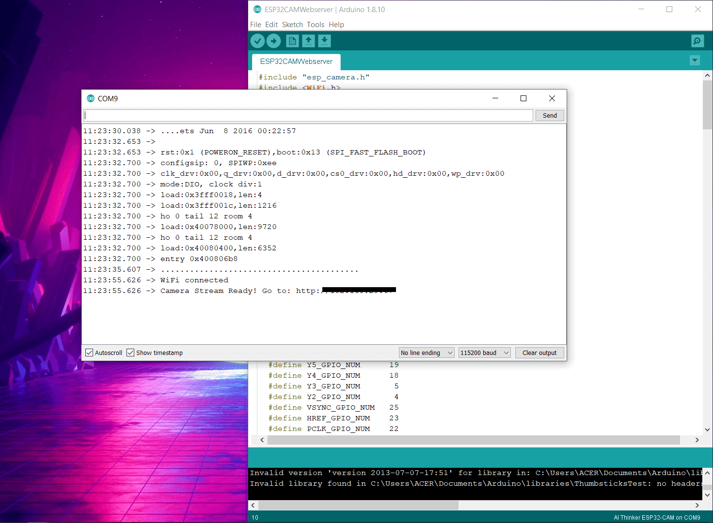
Next, select the upload button. When the following message (Connecting…. ) is displayed, press and hold the RST button for two seconds.
Next, copy and paste the URL on the desktop or mobile internet browser.
Testing
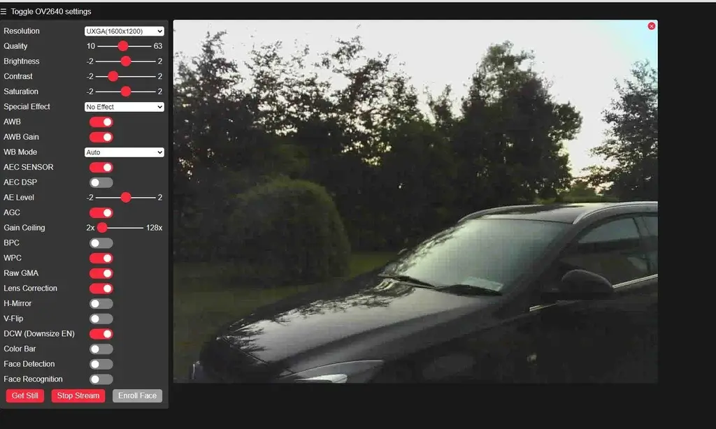
Now you can see the camera view interface. You can change these settings as you wish. Finally, click the “Start Stream” button.

