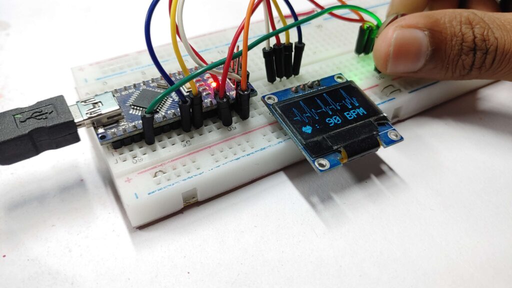
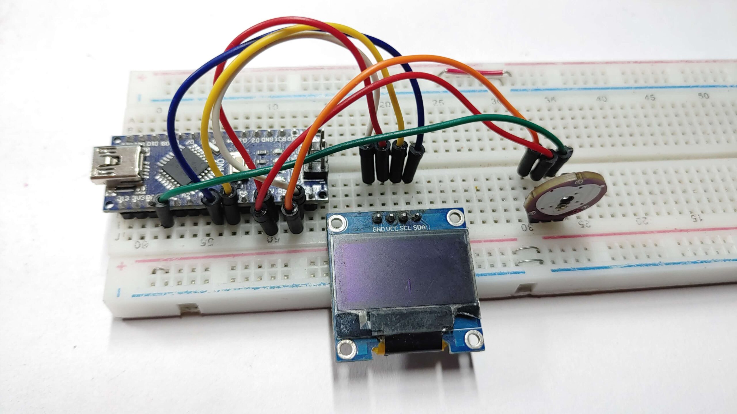
The Heart Beat Display using Pulse Sensor with Arduino & OLED is a project that displays the user’s heart rate on an OLED display using an Arduino and a pulse sensor. this project is perfect for anyone interested in health monitoring, or wearable technology. Start making your Arduino heart rate monitor today.
The project is controlled by a simple code that reads the heart rate sensor data and displays it on the OLED display. Pulse sensors can be used to track the user’s heart rate and can be used to monitor their health in real time.
- A pulse sensor is used to measure heart rate by detecting the amount of blood flow through the body.
- Arduino is used to process the signal from the sensor and calculate the heart rate.
- OLED is used to display the heart rate in beats per minute. The system can be used to monitor heart rate in real-time or to record heart rate data over time.
- Required Material
Required Material
You will need the following components
- Arduino Board
- Pulse sensor
- 0.96″ OLED display
- Jumper wires
- Breadboard
Pulse sensor Arduino
A pulse sensor can measure the changes in blood flow generated by your heartbeat. Pulse sensors can be placed on different parts of your body, such as your fingertip, or wrist. Pulse sensors are generally used in health and fitness tracking, as well as in medical settings to monitor patients’ heart rates.
The pulse sensor uses a light source and detector to detect the changes in blood flow. Your heart pumps blood through your body, and the amount of blood in your blood vessels changes with each beat. It works by shining a light glow into your skin and calculating how much of that light is absorbed by your blood vessels.
Pulse sensor Pinout
The pulse sensor has three pins: VCC, GND, and analog Pin.
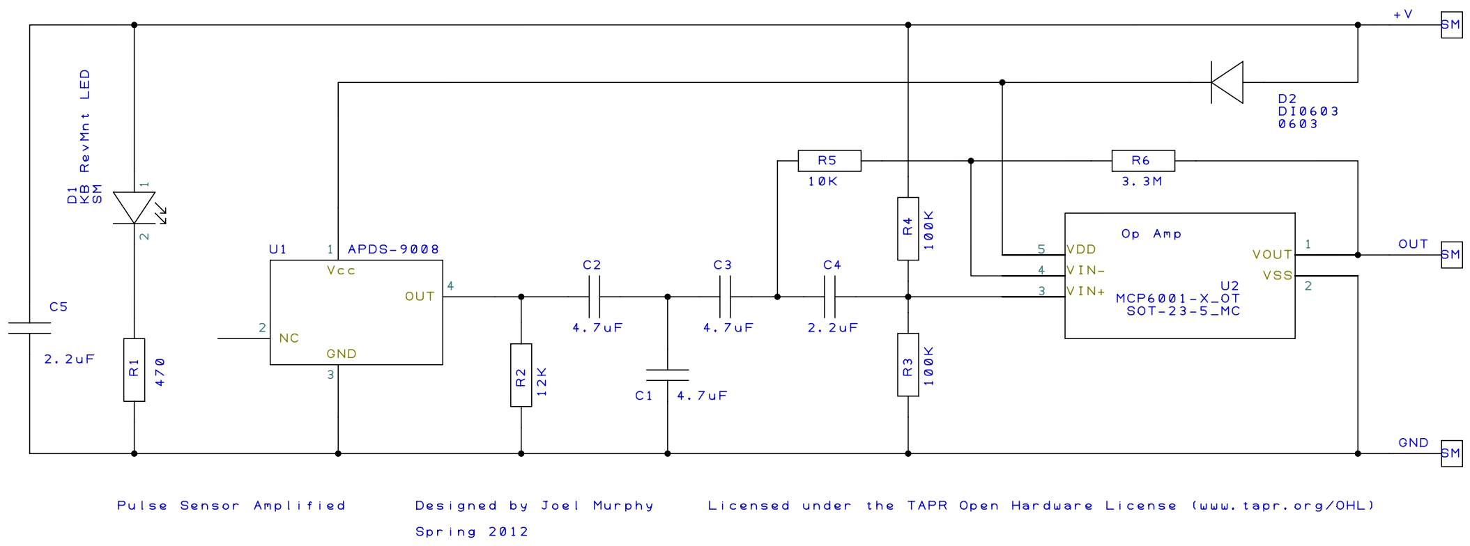
Pulse sensor Schematic
Pulse sensor Specs
- Powering:
- Operating voltage: 3.3V to 5V DC
- Current consumption: less than 10mA
- Heart rate measurement:
- Detection Method: Photoplethysmography (PPG)
- Detection range: 30 to 200 beats per minute (BPM)
- Accuracy: +/- 1 BPM
- Resolution: 1 BPM
- LED Wavelength: 660nm or 940nm (depending on the model)
- Physical dimensions:
- Sensor size: 20mm x 10mm x 5mm
- Weight: 3g to 5g
- Environmental conditions:
- Operating temperature: -10°C to +50°C
- Operating humidity: 0% to 90% non-condensing
Applications of pulse sensors
- Health and fitness tracking
- Sleep Tracking
- Medical monitoring (e.g. in hospitals, ambulances)
- Consumer electronics (e.g. smartwatches, fitness trackers)
- Remote patient monitoring
- Smart Health bands
Warning: This sensor has not been approved by the FDA or any medical. It is created for use in hobby projects and demonstrations only.
0.96″ I2C OLED Display
A 0.96″ OLED display is a small, low-power display that uses the I2C protocol to communicate with a microcontroller board. the I2C interface requires only two data lines (SDA and SCL) to transfer data.
OLED (Organic Light Emitting Diode) technology allows the display to emit light without a backlight, resulting in deeper blacks and higher contrast ratios than traditional LCD displays.
OLED display measures 0.96 inches diagonal and is normally used in small electronic projects due to its compact size and low power consumption.
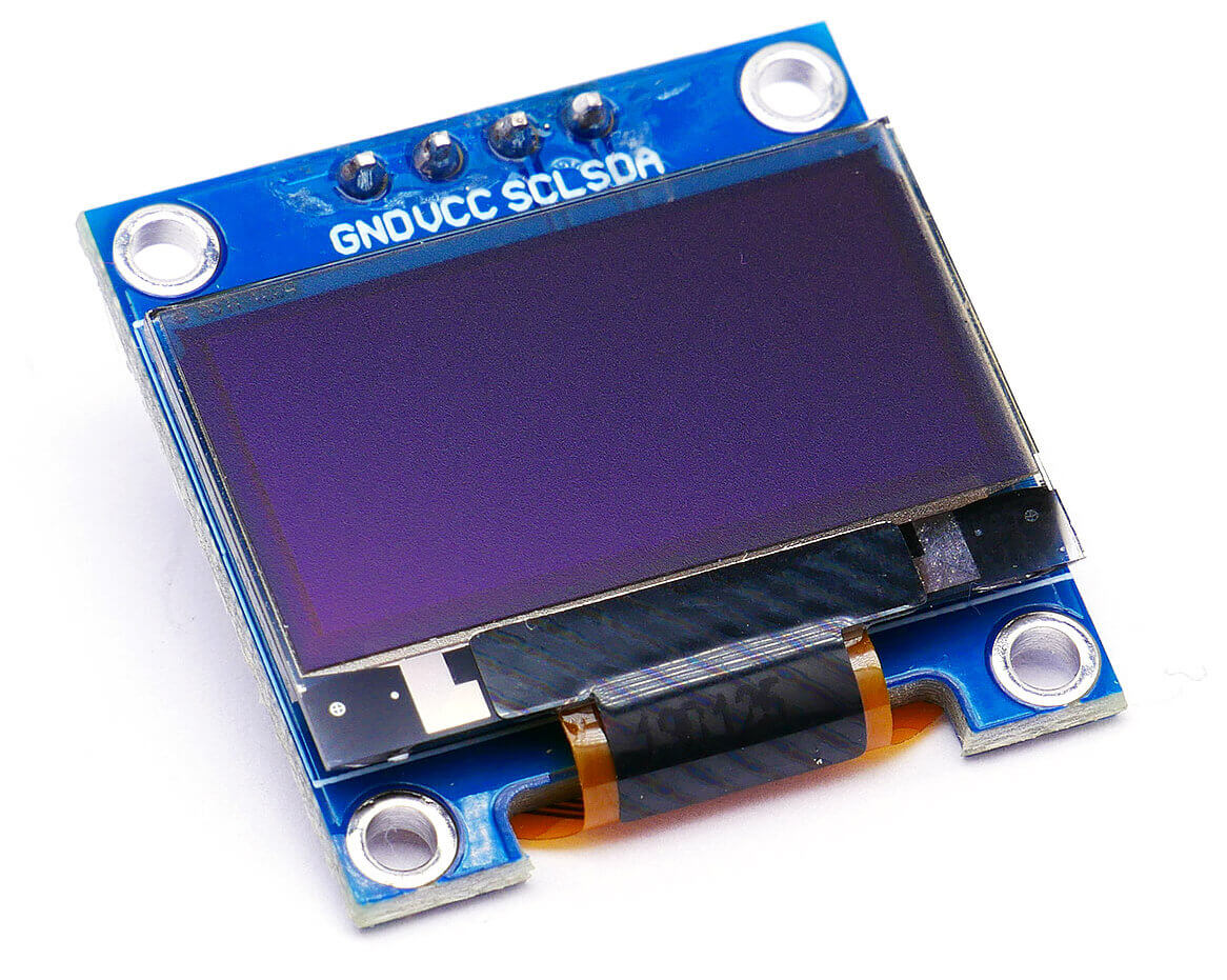
0.96″ I2C OLED Display Pinout
The pinout for the 0.96″ I2C OLED Display is as follows:
- GND: Ground connection
- VCC: Power supply (usually 3.3V or 5V)
- SCL: I2C clock signal input
- SDA: I2C data signal input
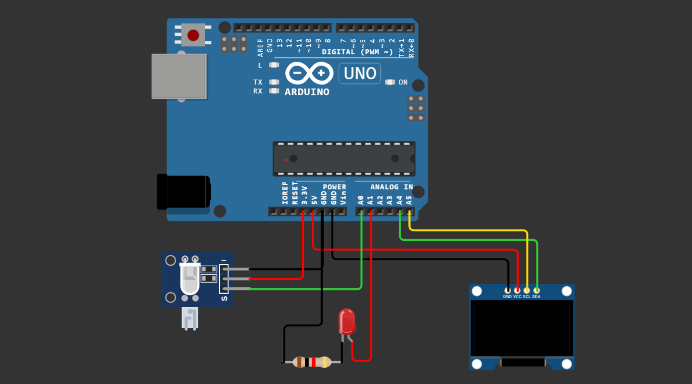
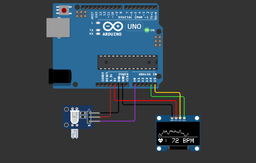
Schematic diagram – Heartbeat sensor Arduino
To connect the pulse sensor with the Arduino, first, connect the VCC pin of the sensor to the 5V pin on the Arduino and connect the GND pin of the sensor to the GND pin. Next, connect the signal pin of the sensor to Analog pin A0.
| Pulse Sensor | Arduino Uno |
|---|---|
| Positive | VCC pin (5V) |
| Negative | GND pin |
| Signal | A0 pin |
For the OLED display, you first need to connect the VCC pin of the display to the 3.3V pin and then connect the GND pin of the display to the GND. connect the SDA and SCK pins of the display to the A4 and A5 pins respectively.
| OLED Display | Arduino Board |
| VCC | 5V |
| GND | GND |
| SDA | A4 |
| SCL | A5 |
Code & Libraries – Pulse Sensor With Arduino & OLED
Download and install Adafruit_GFX and Adafruit_SSD1306 libraries for Arduino.
|
1 2 |
#include <Adafruit_GFX.h> #include <Adafruit_SSD1306.h> |
Example Code Arduino Pulse Sensor
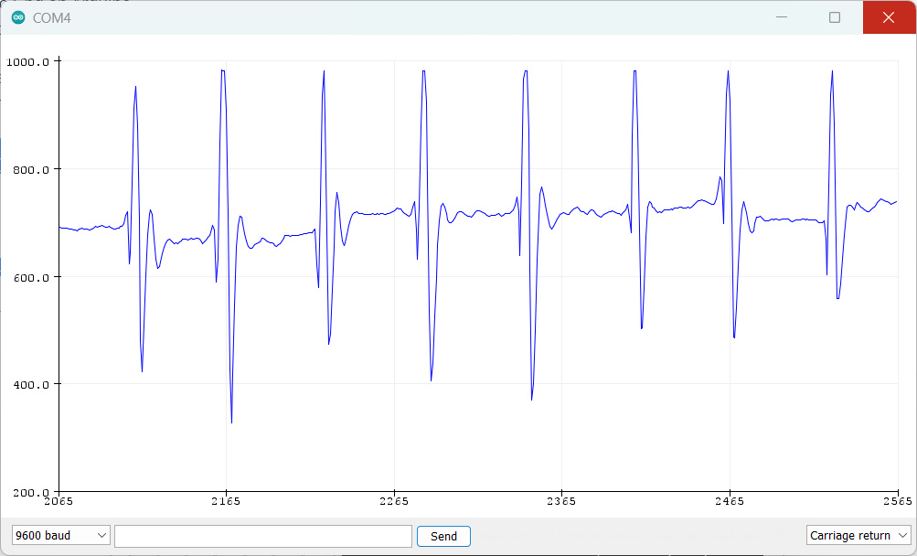
You can use the Arduino IDE with a unique feature that is using an in-built serial monitor plotter to display your heartbeat graphically on the serial monitor window. You will have to load the code below into your IDE and upload it to Arduino. Then select “Tools->Serial Plotter”
|
1 2 3 4 5 6 7 8 9 |
void setup() { Serial.begin(9600); } void loop() { Serial.println(analogRead(0)); delay(20); } |
Here’s my screenshot showing you what to expect.
Source Code
Open Arduino IDE and create a new sketch Copy and paste the following code:
|
1 2 3 4 5 6 7 8 9 10 11 12 13 14 15 16 17 18 19 20 21 22 23 24 25 26 27 28 29 30 31 32 33 34 35 36 37 38 39 40 41 42 43 44 45 46 47 48 49 50 51 52 53 54 55 56 57 58 59 60 61 62 63 64 65 66 67 68 69 70 71 72 73 74 75 76 77 78 79 80 81 82 83 84 85 86 87 88 89 90 91 92 93 94 95 96 97 98 99 100 101 102 103 104 105 106 107 108 109 110 111 112 113 114 115 116 117 118 119 120 121 122 123 124 125 126 127 128 129 130 131 132 133 134 135 136 137 138 139 140 141 142 143 144 145 146 147 148 149 150 151 152 153 154 155 156 157 158 159 160 161 162 163 164 165 |
// Include Libraries #include <SPI.h> #include <Wire.h> #include <Adafruit_GFX.h> #include <Adafruit_SSD1306.h> // OLED screen size in pixels #define SCREEN_WIDTH 128 // OLED display width, in pixels #define SCREEN_HEIGHT 64 // OLED display height, in pixels // Declaration for an SSD1306 display connected to I2C (SDA, SCL pins) #define OLED_RESET -1 // Reset pin # (or -1 if sharing Arduino reset pin) Adafruit_SSD1306 display(SCREEN_WIDTH, SCREEN_HEIGHT, &Wire, OLED_RESET); // Variable Declarations unsigned long previousMillisGetHR = 0; // Store last time Millis (to get Heartbeat) was updated. unsigned long previousMillisResultHR = 0; // Store last time Millis (to get BPM) was updated. const long intervalGetHR = 20; // Interval for reading heart rate (Heartbeat) = 10ms. const long intervalResultHR = 10000; // The reading interval for the result of the Heart Rate calculation is in 10 seconds. int PulseSensorSignal; // Variable to accommodate the signal value from the sensor const int PulseSensorHRWire = 0; // PulseSensor connected to ANALOG PIN 0 (A0 / ADC 0). const int LED_A1 = A1; // LED to detect when the heart is beating. The LED is connected to PIN A1 on the Arduino UNO. int UpperThreshold = 550; // Determine which Signal to "count as a beat", and which to ignore. int LowerThreshold = 500; int cntHB = 0; // Variable for counting the number of heartbeats. boolean ThresholdStat = true; // Variable for triggers in calculating heartbeats. int BPMval = 0; // Variable to hold the result of heartbeats calculation. int x=0; // Variable axis x graph values to display on OLED int y=0; // Variable axis y graph values to display on OLED int lastx=0; // The graph's last x axis variable value to display on the OLED int lasty=0; // The graph's last y axis variable value to display on the OLED // 'Heart_Icon', 16x16px - I drew this heart icon at: http://dotmatrixtool.com/ const unsigned char Heart_Icon [] PROGMEM = { 0x00, 0x00, 0x18, 0x30, 0x3c, 0x78, 0x7e, 0xfc, 0xff, 0xfe, 0xff, 0xfe, 0xee, 0xee, 0xd5, 0x56, 0x7b, 0xbc, 0x3f, 0xf8, 0x1f, 0xf0, 0x0f, 0xe0, 0x07, 0xc0, 0x03, 0x80, 0x01, 0x00, 0x00, 0x00 }; // Setup function void setup() { pinMode(LED_A1,OUTPUT); // Set LED_3 PIN as Output. Serial.begin(9600); // Set up Serial Communication at a certain speed. // SSD1306_SWITCHCAPVCC = generate display voltage from 3.3V internally // Address 0x3C for 128x32 and Address 0x3D for 128x64. // But on my 128x64 module the 0x3D address doesn't work. What works is the 0x3C address. // So please try which address works on your module. if(!display.begin(SSD1306_SWITCHCAPVCC, 0x3C)) { Serial.println(F("SSD1306 allocation failed")); for(;;); //--> Don't proceed, loop forever } // Show initial display buffer contents on the screen // the library initializes this with an Adafruit splash screen. display.display(); delay(1000); // Displays BPM value reading information display.clearDisplay(); display.setTextSize(1); display.setTextColor(WHITE); display.setCursor(0, 12); //--> (x position, y position) display.print(" Please wait"); display.setCursor(0, 22); //--> (x position, y position) display.print(" 10 seconds"); display.setCursor(0, 32); //--> (x position, y position) display.print(" to get"); display.setCursor(0, 42); //--> (x position, y position) display.print(" the Heart Rate value"); display.display(); delay(3000); // Displays the initial display of BPM value display.clearDisplay(); //--> for Clearing the display display.drawBitmap(0, 47, Heart_Icon, 16, 16, WHITE); //--> display.drawBitmap(x position, y position, bitmap data, bitmap width, bitmap height, color) display.drawLine(0, 43, 127, 43, WHITE); //--> drawLine(x1, y1, x2, y2, color) display.setTextSize(2); display.setTextColor(WHITE); display.setCursor(20, 48); //--> (x position, y position) display.print(": 0 BPM"); display.display(); Serial.println(); Serial.println("Please wait 10 seconds to get the BPM Value"); } void loop() { GetHeartRate(); // Calling the GetHeartRate() subroutine } void GetHeartRate() { // Process of reading heart rate. unsigned long currentMillisGetHR = millis(); if (currentMillisGetHR - previousMillisGetHR >= intervalGetHR) { previousMillisGetHR = currentMillisGetHR; PulseSensorSignal = analogRead(PulseSensorHRWire); if (PulseSensorSignal > UpperThreshold && ThresholdStat == true) { cntHB++; ThresholdStat = false; digitalWrite(LED_A1, HIGH); } if (PulseSensorSignal < LowerThreshold) { ThresholdStat = true; digitalWrite(LED_A1, LOW); } DrawGraph(); // Calling the DrawGraph() subroutine } // Process for getting the BPM value. unsigned long currentMillisResultHR = millis(); if (currentMillisResultHR - previousMillisResultHR >= intervalResultHR) { previousMillisResultHR = currentMillisResultHR; BPMval = cntHB * 6; // The taken heart rate is for 10 seconds. So to get the BPM value, the total heart rate in 10 seconds x 6. Serial.print("BPM : "); Serial.println(BPMval); display.fillRect(20, 48, 108, 18, BLACK); display.drawBitmap(0, 47, Heart_Icon, 16, 16, WHITE); display.drawLine(0, 43, 127, 43, WHITE); display.setTextSize(2); display.setTextColor(WHITE); display.setCursor(20, 48); display.print(": "); display.print(BPMval); display.print(" BPM"); display.display(); cntHB = 0; } } void DrawGraph() { // Condition to reset the graphic display if it fills the width of the OLED screen if (x > 127) { display.fillRect(0, 0, 128, 42, BLACK); x = 0; lastx = 0; } // Process signal data to be displayed on OLED in graphic form int ySignal = PulseSensorSignal; if (ySignal > 850) ySignal = 850; if (ySignal < 350) ySignal = 350; int ySignalMap = map(ySignal, 350, 850, 0, 40); y = 40 - ySignalMap; // Displays the heart rate graph display.writeLine(lastx, lasty, x, y, WHITE); display.display(); lastx = x; lasty = y; x++; } |
Uploading the Code
Connect the Arduino board to your computer using USB cable Select the board type and serial port in the Arduino IDE Click the “Upload” button to upload the code to the Arduino board. If you are interested in simulating Arduino, then you can visit this Wokwi website.
Working
After uploading the code wait a few seconds to calibrate the pulse sensor.
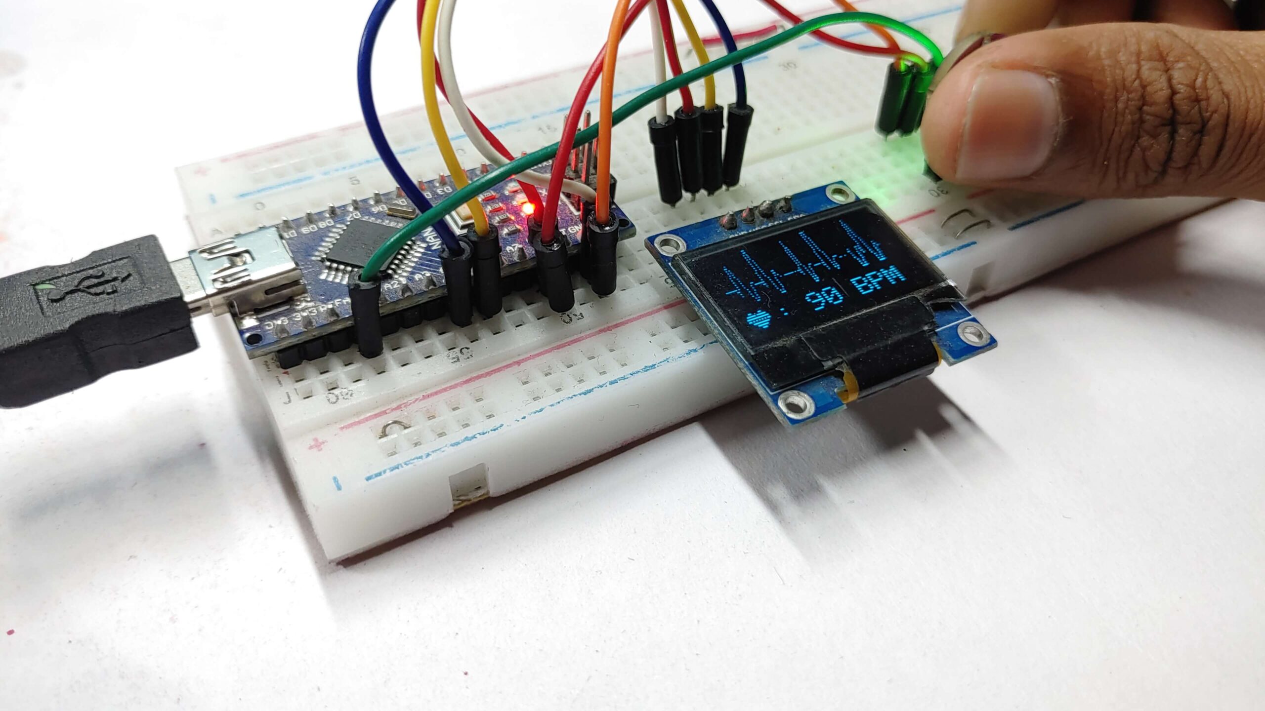
Place your finger on the Pulse Sensor to measure your heart rate
The OLED display should show your heart rate in beats per minute (BPM).

