In this tutorial, we will learn how to build a Home Automation Using Raspberry Pi Pico & Bluetooth module with MicroPython Code. Control your electronic appliances with your smartphone.
Bluetooth-controlled home automation technology allows users to control remotely different devices in their homes such as lighting, air conditioning, and security systems. using Bluetooth-enabled devices like a smartphone, tablets, or laptops.
The Bluetooth module receives signals from the smartphone and transmits data to the microcontroller.
Thank You NextPCB:
Thanks to the support and sponsorship from NextPCB, this project has been completed successfully. I would like to forcefully recommend NextPCB for all your PCBs. Be sure to see their website for exciting discounts, coupons, and more.
- Only 0$ for 5-10pcs PCB Prototypes:Nextpcb.com/pcbprototype
- Register and get $100 from NextPCB: Nextpcb.com/coupon
Requires Material
- Raspberry Pi Pico
- 4- Channel Relay module
- Jumper wires
- AC load (such as light bulbs or fans)
Collect the all required hardware components.
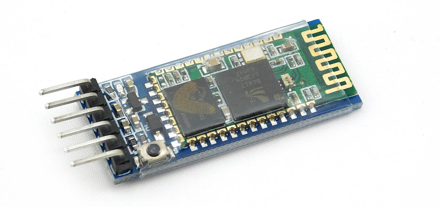
HC-05 Bluetooth module
The HC-05 is a popular Bluetooth module that can be used for wireless transmission between microcontrollers It has a range of up to 10 meters with UART communication protocols. One of the most common uses for the HC-05 module is in home automation systems where it can be used to control lights, fans, and other appliances using a smartphone.
HC-05 Bluetooth module can be easily connected to microcontrollers such as Arduino and ESP8266/ESP32. check out the Interfacing HC-05 Bluetooth Module With Raspberry Pi Pico
HC-05 Bluetooth module Pinout
The HC-05 Bluetooth module has a 6-pin for attaching to a microcontroller. Here is the pinout diagram for the HC-05 module:
HC-05 Pin Description
- EN: Enable pin
- VCC: Power supply voltage (3.6V to 6V)
- GND: Ground
- RXD: Receive data pin
- TXD: Transmit data pin
- STATE: Status pin
Note: STATE and EN pins are optional they are not required for basic communication with the microcontroller.
Features of HC-05 Bluetooth module
- Bluetooth version: Bluetooth 2.0 + EDR (Enhanced Data Rate)
- Frequency band: 2.4GHz ISM band
- Sensitivity: -80dBm
- Communication Range: up to 10 meters
- UART interface: 9600 bps
- Power supply voltage: 3.6V – 6V DC
- Operating current: <30mA
- Operating temperature: –20°C to +75°C
- Dimensions: 27mm x 13mm x 2.2mm
HC 05 Module is easy to combine with microcontrollers and other devices and is generally used in home automation, robotics, and DIY projects.
Wiring Diagram – Home Automation Using Raspberry Pi Pico
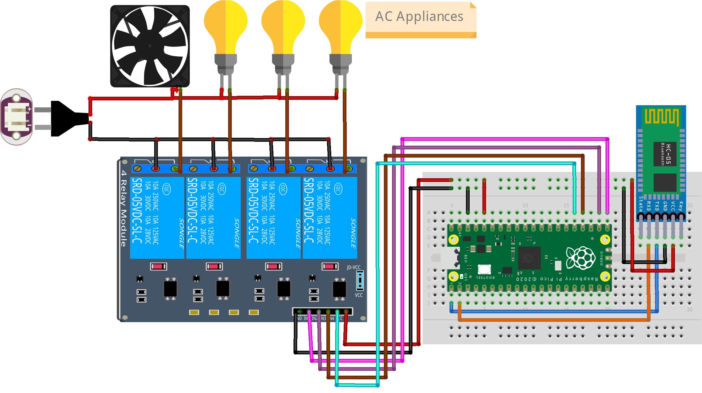
Here is a wiring diagram for a home automation system using Raspberry Pi Pico & HC 05 Bluetooth module
You can also follow my mapping
| HC -05 Module | RASPBERRY PI PICO |
|---|---|
| VCC | 3.3V |
| GND | GND |
| RX | GP0 |
| TX | GP1 |
Relay –> Raspberry Pi ico
- VCC –> 5V
- GND –> GND
- IN1=> GP16
- IN2 => GP17
- IN3=> GP18
- IN4 => GP19
- COM terminal => Supply from mains
- NO terminal => Supply line to bulb
Recommended reading: Getting Started Raspberry Pi Pico – Pinout, Specs
Connect the Devices
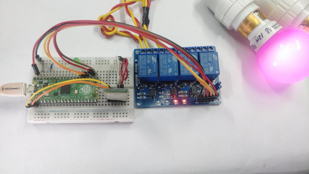
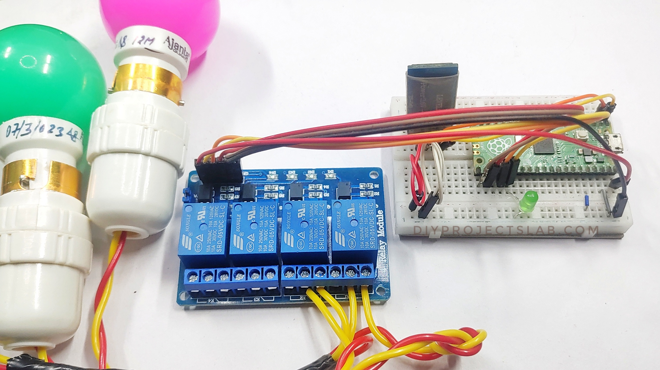
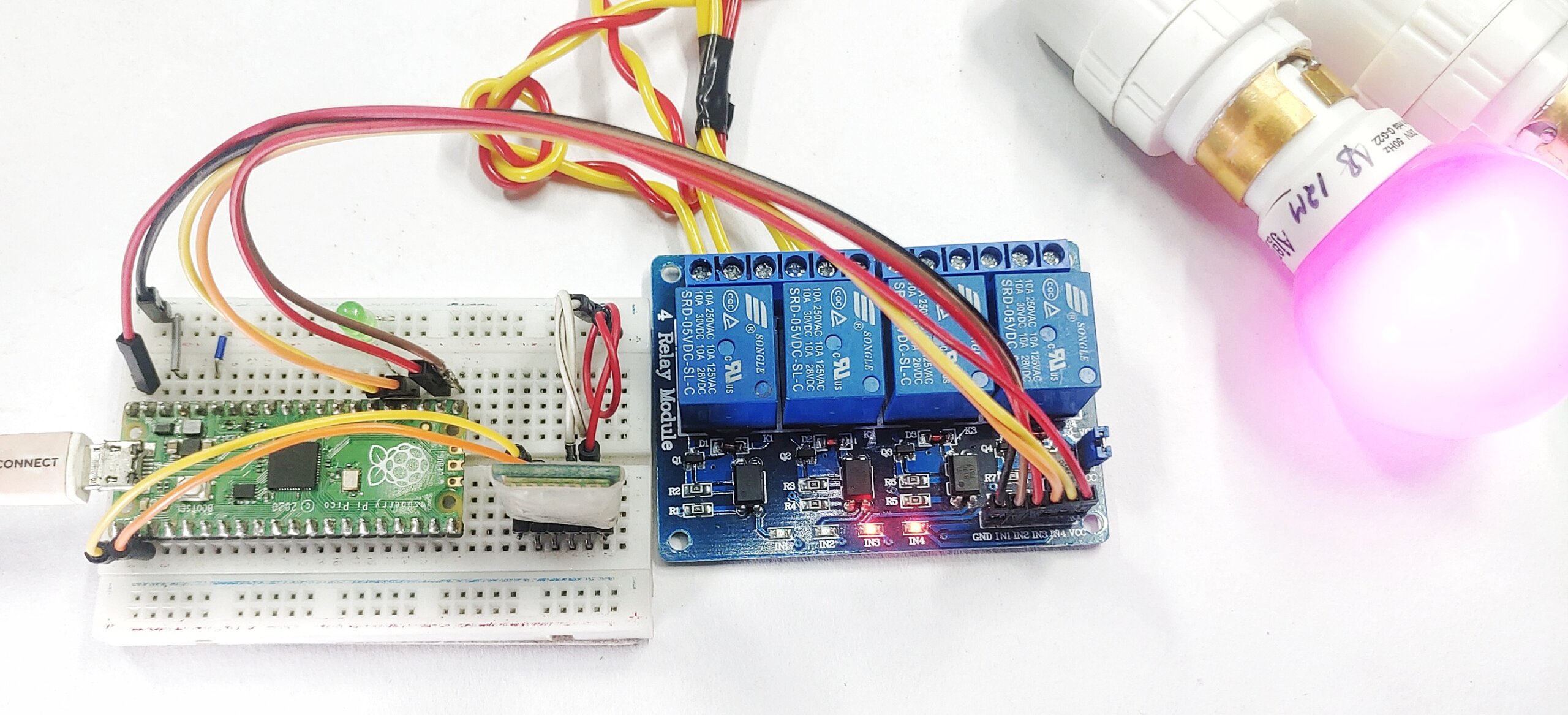
Since we are using a four-channel relay module & we will be controlling two bulbs.
Bluetooth App configure
Serial Bluetooth Terminal is an Android application that allows you to communicate with a Microcontroller like a Raspberry pi pico board with Bluetooth. With this app, you can send and receive data from your Pico board wirelessly. Download Serial Bluetooth Terminal
Here is the step to use the Serial Bluetooth Terminal
To connect to the Pico for the first time, you need to Pair your Android device with a Bluetooth module.
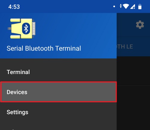
Go to Devices.
Open the Bluetooth Serial Monitor app. On the menu bar, connect Bluetooth Devices:
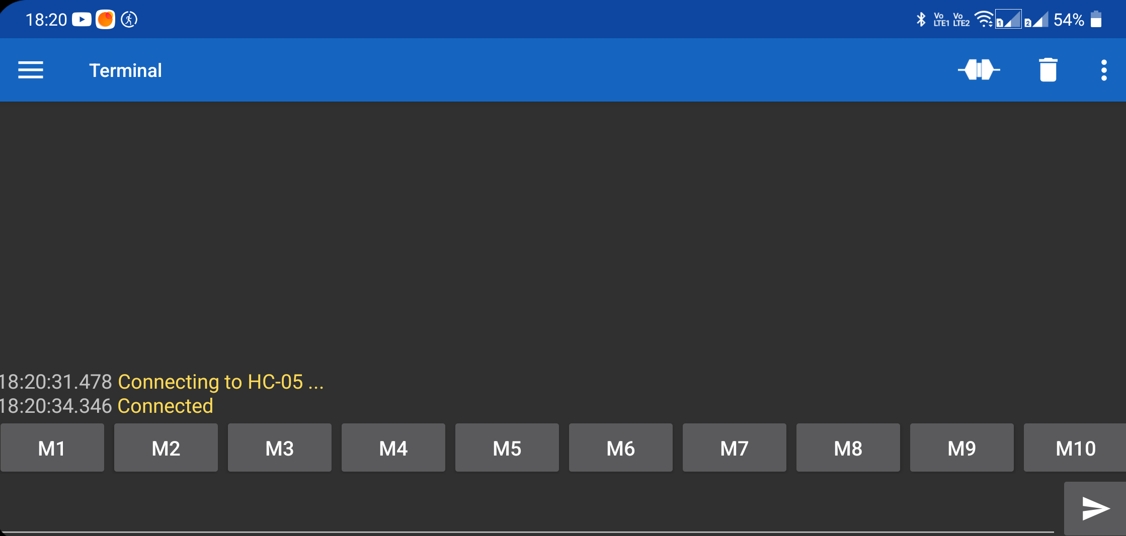
Send and receive data from the pico board using the Serial Bluetooth Terminal app.
Micropython Code – Home Automation Using Raspberry Pi Pico & Bluetooth
After assembling the circuit, copy the following sketch to your Thonny IDE.
copy the below code and save it in the Pico board as the “main.py” name.
|
1 2 3 4 5 6 7 8 9 10 11 12 13 14 15 16 17 18 19 20 21 22 23 24 25 26 27 28 29 30 31 32 33 34 35 36 37 38 39 40 41 42 |
from machine import Pin from machine import UART from time import sleep HC05=UART(0,9600) relay_1=Pin(16,Pin.OUT) relay_2=Pin(17,Pin.OUT) relay_3=Pin(18,Pin.OUT) relay_4=Pin(19,Pin.OUT) while True: if HC05.any()>0: data=HC05.read(1) if "a" in data: relay_1.on() if "b" in data: relay_1.off() if "c" in data: relay_2.on() if "d" in data: relay_2.off() if "e" in data: relay_3.on() if "f" in data: relay_3.off() if "g" in data: relay_4.on() if "h" in data: relay_4.off() |
Testing the Project
You can write the following commands.
- “a” and “b” messages to control the first Relay.
- “c” and “d” messages to control the second Relay.
- “e” and “f” messages to control the third Relay.
- “g” and “h” messages to control the fourth Relay.
The application has several controls which means you can save default messages. For example, you can associate M1 with the “a” message, and M2 with the “b” message.
Now, you are able to control the Pico.
The relay will be on when you press Bulb on a button.
Raspberry Pi Pico Projects
- How To Make Raspberry Pi Pico W Web Server – MicroPython
- MFRC522 RFID Module With Raspberry Pi Pico Using MicroPython
- Interfacing Raspberry Pi Pico With VGA Monitor
- Water-Flowing LED Lights With Raspberry Pi Pico W
- Interfacing PIR Motion Sensor with Raspberry Pi Pico
- BME280 With Raspberry Pi Pico W Using MicroPython





1 Comment
Interesting 😊