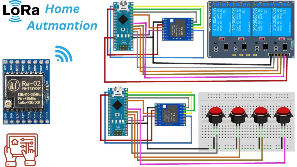
This tutorial shows you how to use Arduino and LoRa technology to create a home automation system. In this project, we will use Arduino and SX1278 LoRa Module to build a home automation system that can control Elextronics appliances s wirelessly.
LoRa (Long Range) technology is a wireless communication protocol designed for long-range communication with low power consumption. It operates in the unlicensed radio spectrum, making it accessible and widely used for various IoT (Internet of Things) applications.
Required Material
You’ll need the following components to build.
- Arduino board
- LoRa module (e.g., SX1278)
- Relay
- Jumper wires
- Breadboard
- Power supply
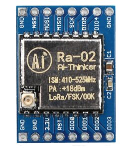
SX1278 LoRa module
The SX1278 is a popular LoRa module that can be used for long-range wireless communication. It operates in the 433MHz or 868MHz frequency bands and is capable of performing long-distance communication with low power consumption. Here you can find the basic knowledge on how to use the SX1278 LoRa module:
The SX1278 LoRa module allows us to establish wireless communication over long distances. Typical rural distances are several kilometers and in urban environments hundreds of meters.
It is capable of reaching this range while consuming a small amount of power, which makes it well-suited for battery-powered applications.
With the SX1278 LoRa module, you can create wireless communication links between different nodes in a network, enabling remote sensing, control, and monitoring in various applications Checkout my previous post to learn more about LoRa Communication and How to use it with Arduino
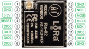
SX1278 LoRa module Pinout
SX1278 LoRa module Specification
- Working voltage: 1.8-3.7V
- Frequency Bands: 433MHz or 915MHz
- Supports FSK, GFSK, MSK, GMSK, LoRa, and OOK modulation modes
- Modulation Schemes: Spectrum modulation and FSK modulation
- Communication Range: 15 kilometers in optimal conditions
- Sensitivity: 148 dBm
- Output Power: Adjustable, typically up to +20dBm (100mW)
- Interface: Half-duplex SPI communication
- Power Consumption: Designed for low-power applications
- Antenna: Requires an external antenna
- Automatic RF signal detection and CAD mode
- Programmable bit rates up to 300kbps
- Working temperature : -40°C to +80°C
Interfacing LoRa With Arduino
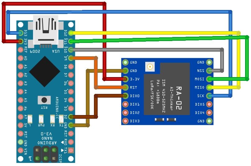
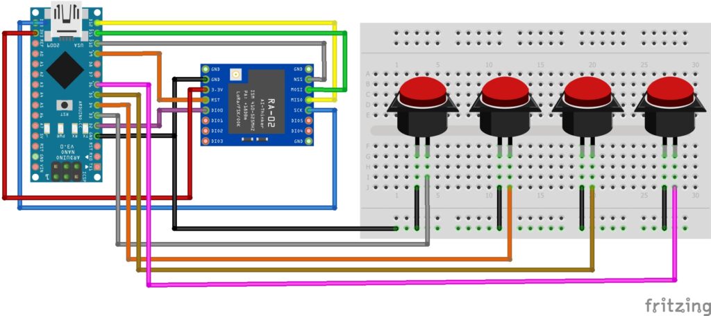
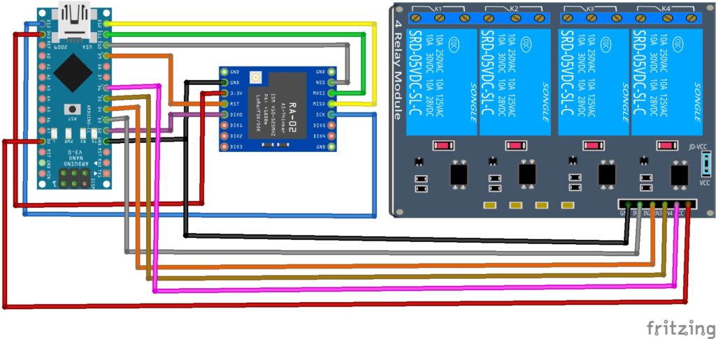
Connect the LoRa module to your Arduino board. Typically, the LoRa module uses SPI communication. Here is the following pins connection:
Connect the LoRa module to the Arduino board using jumper wires. Make the following connections:
LoRa module —-> Arduino
- VCC to 3.3V
- GND to GND
- MISO to D12
- MOSI to D11
- SCK to D13
- NSS to D10
- DIO0 to D2
Arduino LoRa SX1278 Transmitter
Button —> Arduino
- GND to GND
- Button_1 to D3
- Button_2 to D4
- Button_3 to D5
- Button_4 to D6
Arduino LoRa SX1278 Receiver
Relay —-> Arduino
- VCC to 5V
- GND to GND
- IN1 to D3
- IN2 to D4
- IN3 to D5
- IN4 to D6
Source code & libraries
Install required libraries
To work with LoRa you’ll need to install the necessary libraries.
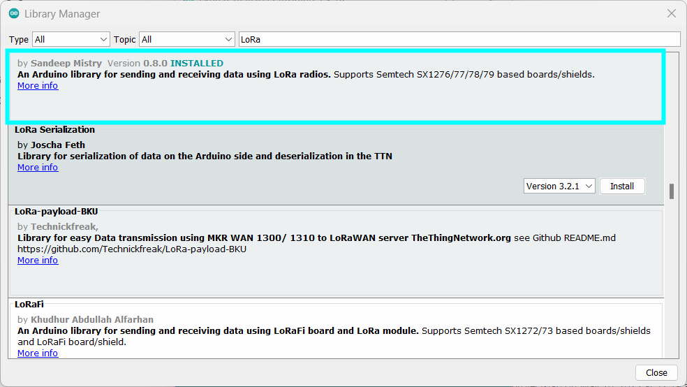
You can install these libraries through the Arduino IDE by going to “Sketch” -> “Include Library” -> “Manage Libraries.” Search “LoRA” in the search Bar and install LoRa By Sandeep Mistry Library.
You can also download the library from here Arduino-LoRa-master
Transmitter Code
|
1 2 3 4 5 6 7 8 9 10 11 12 13 14 15 16 17 18 19 20 21 22 23 24 25 26 27 28 29 30 31 32 33 34 35 36 37 38 39 40 41 42 43 44 45 46 47 48 49 50 51 52 53 54 55 56 57 58 59 60 61 |
#include <SPI.h> #include <LoRa.h> #define BUTTON_1 3 #define BUTTON_2 4 #define BUTTON_3 5 #define BUTTON_4 6 void setup() { Serial.begin(9600); pinMode(BUTTON_1, INPUT); pinMode(BUTTON_2, INPUT); pinMode(BUTTON_3, INPUT); pinMode(BUTTON_4, INPUT); while (!Serial); Serial.println("LoRa Sender"); if (!LoRa.begin(433E6)) { Serial.println("Starting LoRa failed!"); while (1); } LoRa.setTxPower(20); } void sendPacket(const char* data) { LoRa.beginPacket(); LoRa.print(data); LoRa.endPacket(); } void loop() { if (digitalRead(BUTTON_1) == LOW) { // Button 1 pressed, send packet sendPacket("tb1"); while (digitalRead(BUTTON_1) == LOW); } if (digitalRead(BUTTON_2) == LOW) { // Button 2 pressed, send packet sendPacket("tb2"); while (digitalRead(BUTTON_2) == LOW); } if (digitalRead(BUTTON_3) == LOW) { // Button 3 pressed, send packet sendPacket("tb3"); while (digitalRead(BUTTON_3) == LOW); } if (digitalRead(BUTTON_4) == LOW) { // Button 4 pressed, send packet sendPacket("tb4"); while (digitalRead(BUTTON_4) == LOW); } } |
Receiver Code
|
1 2 3 4 5 6 7 8 9 10 11 12 13 14 15 16 17 18 19 20 21 22 23 24 25 26 27 28 29 30 31 32 33 34 35 36 37 38 39 40 41 42 43 44 45 46 47 48 49 50 51 52 53 54 55 56 57 |
#include <SPI.h> #include <LoRa.h> int relay1 = 4; int relay2 = 5; int relay3 = 6; int relay4 = 7; String data = ""; void setup() { Serial.begin(9600); while (!Serial); Serial.println("LoRa Receiver"); pinMode(relay1, OUTPUT); pinMode(relay2, OUTPUT); pinMode(relay3, OUTPUT); pinMode(relay4, OUTPUT); if (!LoRa.begin(433E6)) { Serial.println("Starting LoRa failed!"); while (1); } } void handlePacket(String packet) { if (packet == "relay1") { digitalWrite(relay1, !digitalRead(relay1)); Serial.print("Relay 1: "); Serial.println(digitalRead(relay1)); } else if (packet == "relay2") { digitalWrite(relay2, !digitalRead(relay2)); Serial.print("Relay 2: "); Serial.println(digitalRead(relay2)); } else if (packet == "relay3") { digitalWrite(relay3, !digitalRead(relay3)); Serial.print("Relay 3: "); Serial.println(digitalRead(relay3)); } else if (packet == "relay4") { digitalWrite(relay4, !digitalRead(relay4)); Serial.print("Relay 4: "); Serial.println(digitalRead(relay4)); } } void loop() { int packetSize = LoRa.parsePacket(); if (packetSize) { while (LoRa.available()) { data = LoRa.readString(); } Serial.println(data); LoRa.packetRssi(); handlePacket(data); data = ""; } } |
Working
In conclusion, the provided code is able to implement a LoRa receiver using an Arduino board. The code initializes the LoRa module, sets up the necessary pin modes for controlling the relays, and continuously listens for incoming LoRa packets.
Once a packet is received, the code reads the data and determines the appropriate action based on the received packet. If the packet corresponds to “relay1“, “relay2“, “relay3“, or “relay4“, the corresponding relay’s state is reversed, and the new state is displayed on the Serial monitor.

