ADS1115 is a 16-bit Analog-to-Digital Converter (ADC) with an I2C interface. we can use ADS1115 16-bit ADC With ESP32 board to read analog voltages. In this guide, we will connect the ADS1115 to ESP32 to measure the voltage of a potentiometer with high precision.
In this article, we will explore the interfacing of an ADS1115 16-bit ADC module with the ESP32 microcontroller. ADS1115 is a 16-bit analog-to-digital converter (ADC) from Texas Instruments that can convert an analog voltage signal into a digital value with high precision.
It can easily be interfaced with a variety of microcontrollers such as Arduino, ESP8266/32, STM32, etc.
Overview of ESP32
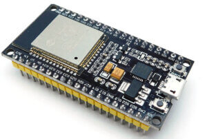
ESP32 is a famous, low-cost, and universal design-on-chip (SoC) developed by Espressif Systems. It connects a dual-core processor, Wi-Fi, and Bluetooth connectivity, and a variety of input/output options for embedded sensors in a single chip. ESP32 uses the Xtensa LX6 processor, a dual-core 32-bit CPU with a clock speed of up to 240 MHz.
ESP32 features
Processors
- Wireless connectivity:
- Wi-Fi: 802.11 b/g/n
- Bluetooth: v4.2 BR/EDR and BLE
Peripheral interfaces
- 34 × programmable GPIOs
- 12-bit SAR ADC up to 18 channels
- 2 × 8-bit DACs
- 4 × SPI
- 2 × I²S interfaces
- 2 × I²C interfaces
- 3 × UART
- 16 PWM channels
- CAN bus communication
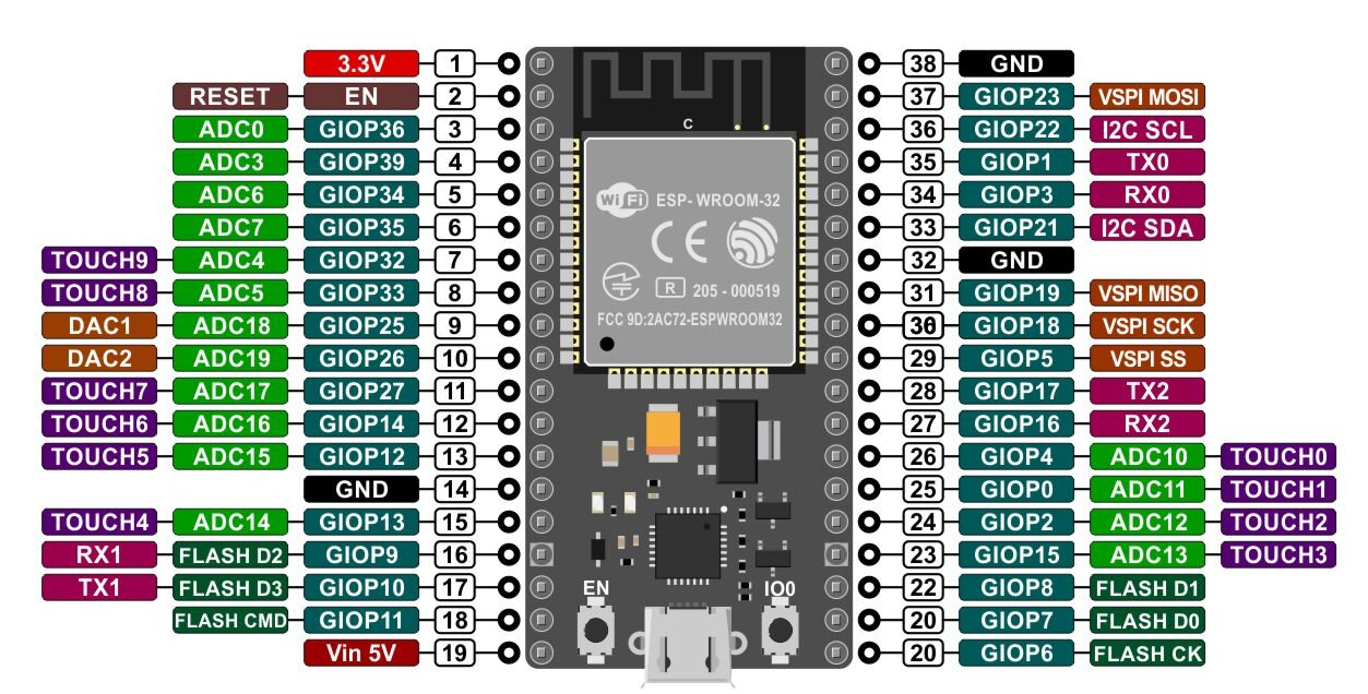
ESP32 Pinout
ESP32 ADC Resolution
The ESP32 has built an analog-to-digital converter (ADC) that can convert analog signals into digital signals which the microcontroller board can do. ESP32 has 12-bit SAR (“Successive Approximation Register”) ADC.
Limitation in Resolution:
The ESP32’s ADC has a resolution of 12 bits, which means it can detect dissimilarities in voltage as diminutive as 0.000244 V (3.3V / 2^12).
ESP32 board offers an extended range of features that include 18 channels of analog measurement support. which means they can convert analog signals with a resolution of 1 part in 4096. ESP32 can be used to measure voltage levels between 0 V and 3.3 V.
Limitation in Nonlinearity:
The built-in 12-bit ADC has a common problem with nonlinearity that can affect the accuracy of measurements. The nonlinearity can cause inaccurate output from the ADC, which presents a challenge when trying to accurately measure analog signals.
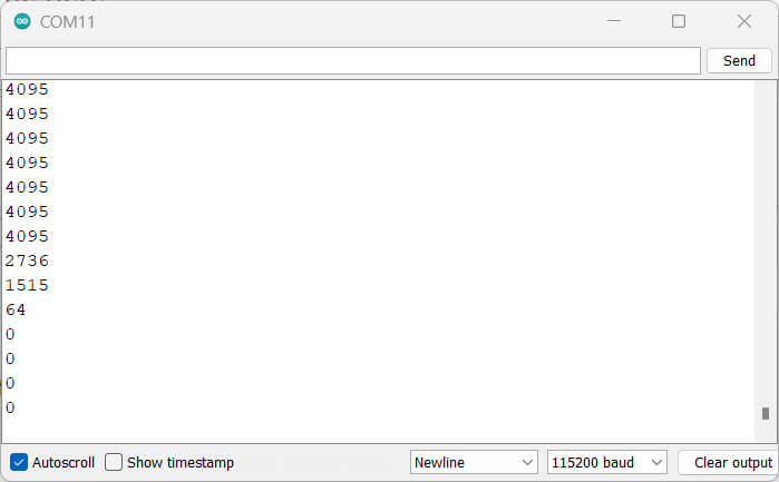
This behavior indicates that the ESP32 microcontroller is unable to differentiate between voltage levels of 3.3V and 3.2V, resulting in both values being represented as 4095. Similarly, for very low voltage values of 0V and 0.1V, the ESP32 returns the same value of 0.
The precision of the conversion results in your projects. The ADS1115 offers a resolution of 16 bits that allows for more precise voltage measurements.
With this improved resolution, the lowest measurable voltage becomes 3.3V / 65536 = 0.000076V (76uV). This enhanced precision can be valuable for projects that require accurate voltage readings.
Read Analog Value using ESP32
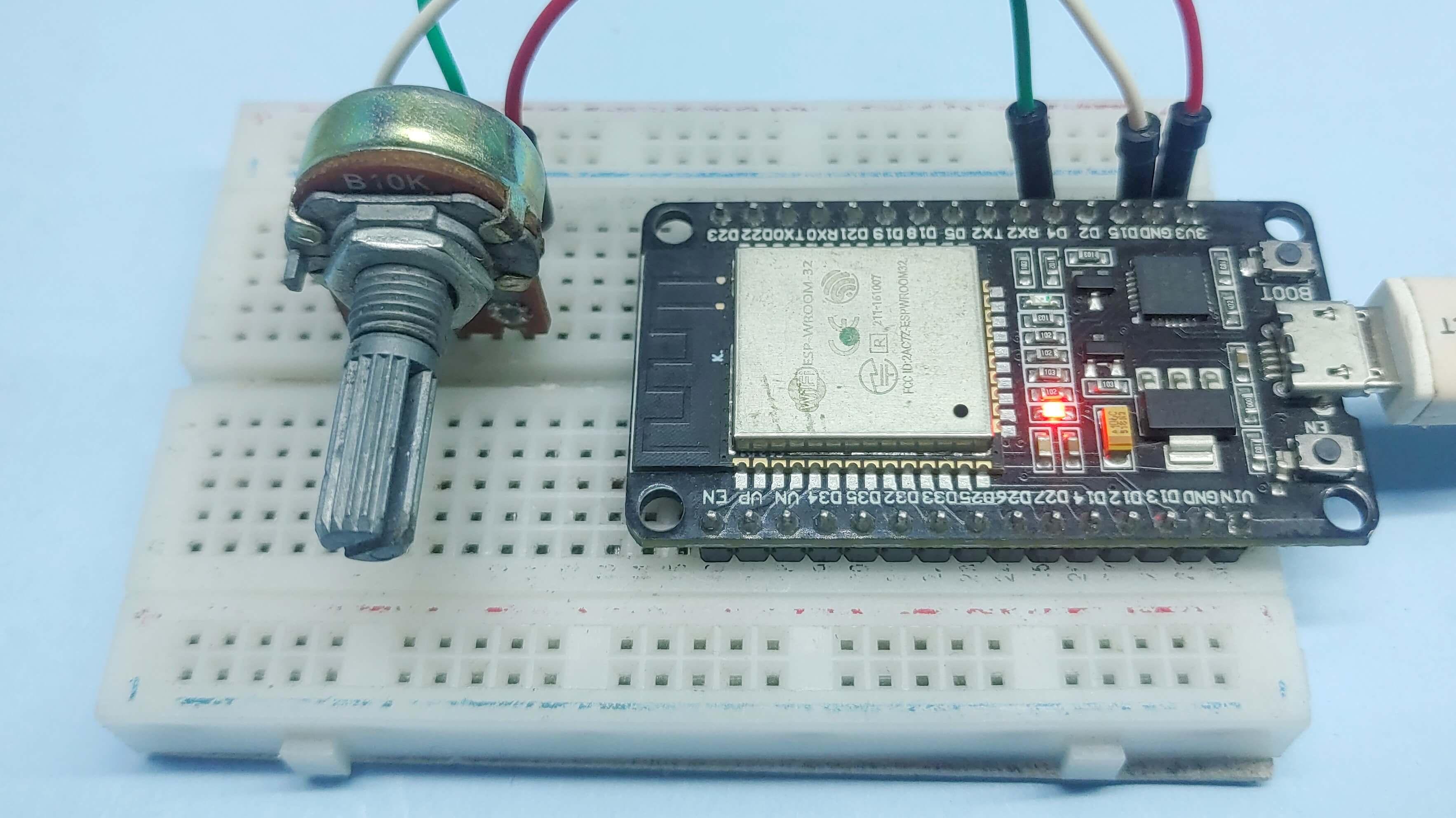
To read analog value with SP32, you have to use one of its built-in Analog-to-Digital Converters pins (ADCs). An example code shows how to read analog values from a potentiometer using the ESP32 Microcontroller board.
|
1 2 3 4 5 6 7 8 9 10 11 12 13 14 15 16 |
const int AnalogPin = 4; // variable for storing the potentiometer value int Analog_Value = 0; void setup() { Serial.begin(115200); delay(100); } void loop() { // Reading potentiometer value Analog_Value = analogRead(AnalogPin); Serial.println( Analog_Value); delay(100); } |
The result
After uploading the code and pressing the ESP32 reset button, open the serial monitor at 115200 baud. Check the values of the potentiometer, and see how it changes when rotated.
The maximum value you can get is 4095. The minimum value is 0.
ADS1115 16-Bit ADC Module
The ADS1115 module is an analog-to-digital converter (ADC) normally used to convert analog to digital signals. The module uses the ADS1115 chip from Texas Instruments, a 16-bit ADC which means that it can describe analog input signal with a max of 2^16 or 65,536 different digital values. with four input channels. It can convert analog signals from -0.256V to +0.256V with a maximum sampling rate of 860 samples per second, and its I2C interface can support speeds up to 3.4 Mbps.
ADS1115 is a high-precision ADC that can be used to measure temperature, pressure, and voltage.
ADS1115 Features
- Wide Supply Range: 2.0 V to 5.5 V
- Low Current Consumption: 150 µA
- Programmable Data Rate:
- 8 SPS to 860 SPS
- Single-Cycle Settling
- Internal Low-Drift Voltage Reference
- Internal Oscillator
- I2C Interface: 4 Pin-Selectable Addresses
- Four Single-Ended or Two Differential Inputs
- Programmable Comparator
- Operating Temperature Range:
- –40°C to +125°C
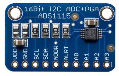
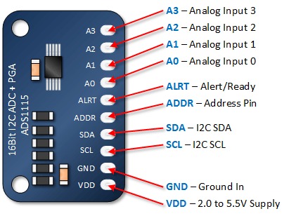
ADS1115 Pinout
Why do we need to use an external ADC with ESP32?
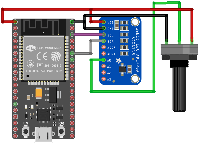
Interfacing ADS1115 16-Bit ADC With ESP32
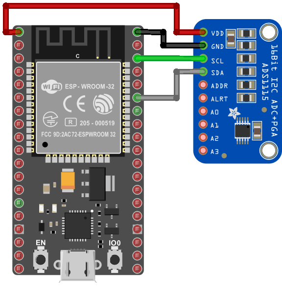
Read Analog Sensor Using ADS1115 16-Bit ADC With ESP32
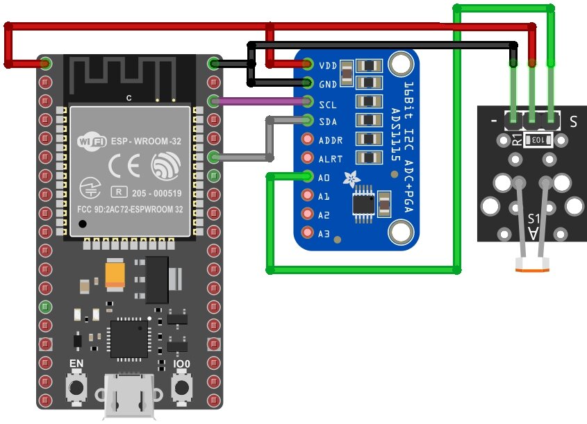
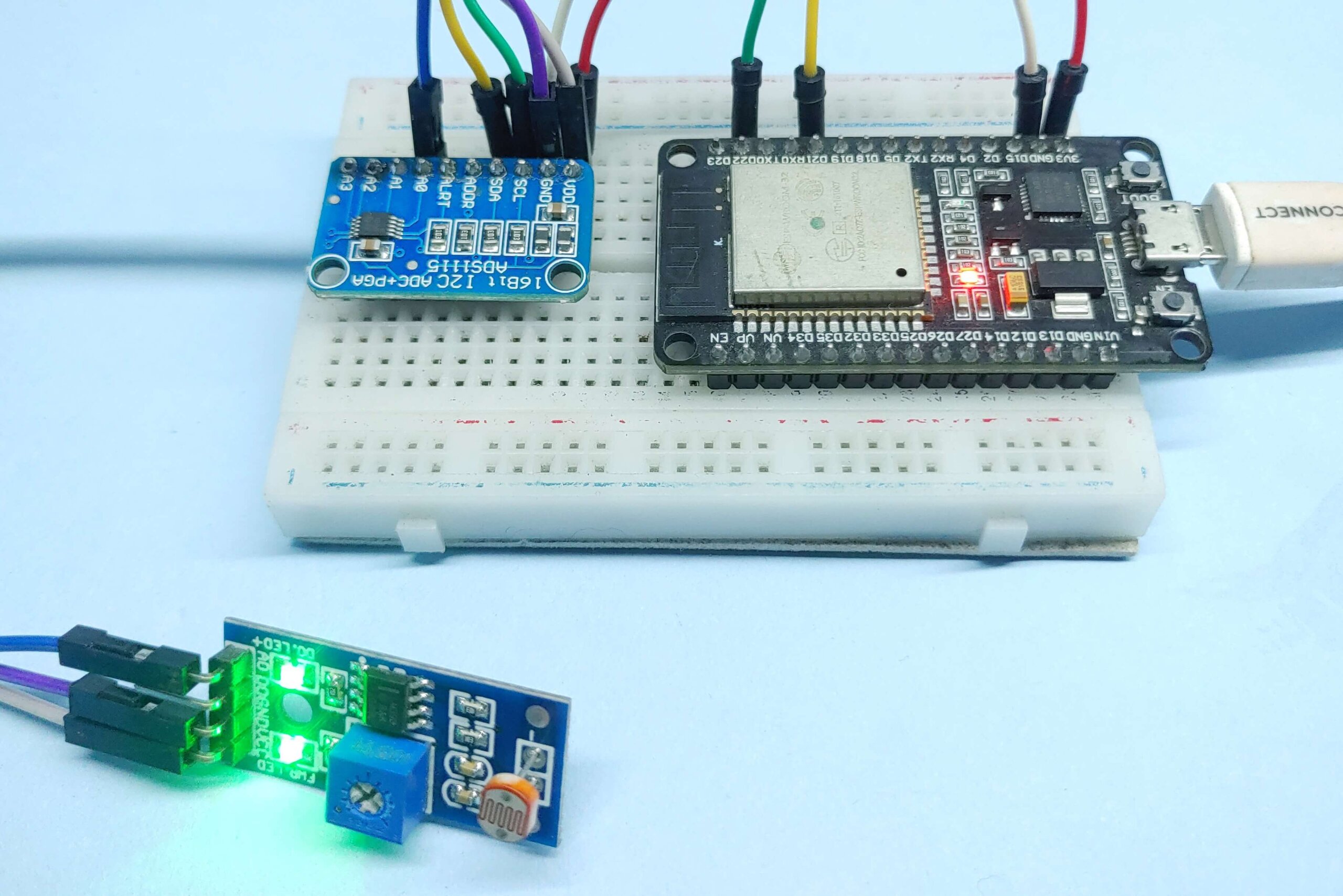
| ESP32 | ADS1115 external ADC |
|---|---|
| VDD | VDD |
| GND | GND |
| GPIO21 ( SDA Pin ) | SDA |
| GPIO22 ( SCL Pin ) | SCL |
| Sensor Signal Pin | A0 of ADS1115 |
You may want to refer to our last post for more detailed information.
- How to Interface ADS1115 16-Bit ADC with Arduino
- Interfacing ADS1115 Analog-to-Digital Converter with Raspberry Pi Pico
- How to Interface ADS1115 16-Bit ADC with ESP8266
- Read Analog Value Using ADS1115 16-Bit ADC with Raspberry Pi
Source Code
|
1 2 3 4 5 6 7 8 9 10 11 12 13 14 15 16 17 18 19 20 21 |
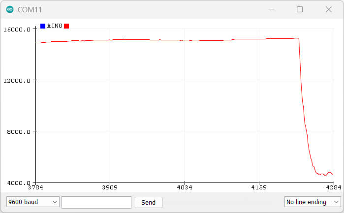
#include <Wire.h> #include <Adafruit_ADS1X15.h> Adafruit_ADS1115 ads; void setup(void) { Serial.begin(9600); ads.begin(); } void loop(void) { int16_t adc0; adc0 = ads.readADC_SingleEnded(0); Serial.print("AIN0: "); Serial.println(adc0); Serial.println(" "); } |
Testing
Voltage Reading with ADS1115 & ESP32
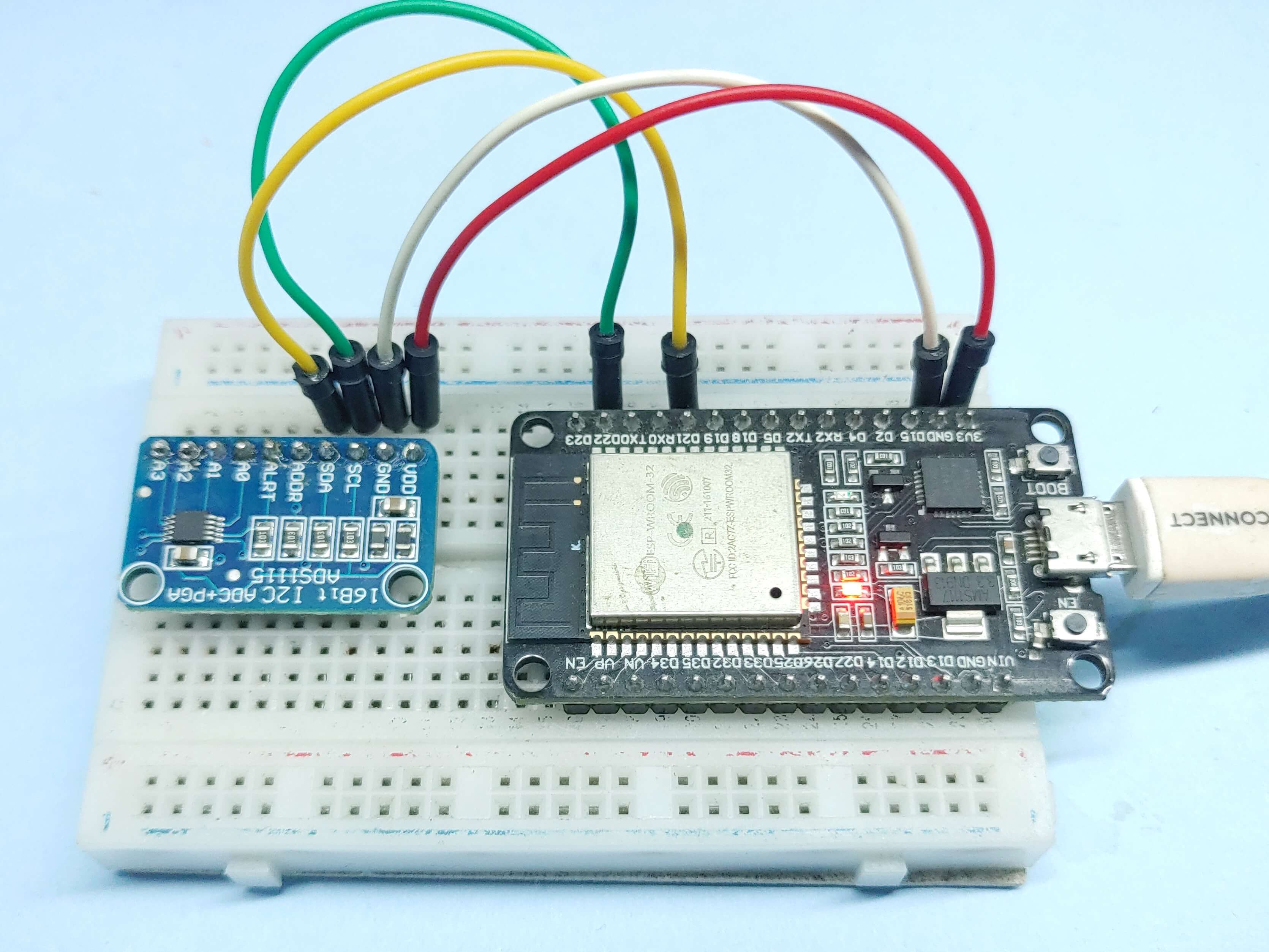
| ESP32 | ADS1115 external ADC |
|---|---|
| 3.3V | VDD |
| GND | GND |
| GPIO21 ( SDA Pin ) | SDA |
| GPIO22 ( SCL Pin ) | SCL |
| Potentiometer signal | A0 |
Source Code
|
1 2 3 4 5 6 7 8 9 10 11 12 13 14 15 16 17 18 19 20 21 22 23 24 25 26 27 28 29 30 31 32 33 34 35 36 37 38 39 40 41 42 43 44 45 46 47 48 49 50 51 52 53 54 55 |
#include <Adafruit_ADS1X15.h> //Adafruit_ADS1115 ads; /* Use this for the 16-bit version */ Adafruit_ADS1015 ads; /* Use this for the 12-bit version */ void setup(void) { Serial.begin(9600); Serial.println("Hello!"); Serial.println("Getting single-ended readings from AIN0..3"); Serial.println("ADC Range: +/- 6.144V (1 bit = 3mV/ADS1015, 0.1875mV/ADS1115)"); // The ADC input range (or gain) can be changed via the following // functions, but be careful never to exceed VDD +0.3V max, or to // exceed the upper and lower limits if you adjust the input range! // Setting these values incorrectly may destroy your ADC! // ADS1015 ADS1115 // ------- ------- // ads.setGain(GAIN_TWOTHIRDS); // 2/3x gain +/- 6.144V 1 bit = 3mV 0.1875mV (default) // ads.setGain(GAIN_ONE); // 1x gain +/- 4.096V 1 bit = 2mV 0.125mV // ads.setGain(GAIN_TWO); // 2x gain +/- 2.048V 1 bit = 1mV 0.0625mV // ads.setGain(GAIN_FOUR); // 4x gain +/- 1.024V 1 bit = 0.5mV 0.03125mV // ads.setGain(GAIN_EIGHT); // 8x gain +/- 0.512V 1 bit = 0.25mV 0.015625mV // ads.setGain(GAIN_SIXTEEN); // 16x gain +/- 0.256V 1 bit = 0.125mV 0.0078125mV if (!ads.begin()) { Serial.println("Failed to initialize ADS."); while (1); } } void loop(void) { int16_t adc0, adc1, adc2, adc3; float volts0, volts1, volts2, volts3; adc0 = ads.readADC_SingleEnded(0); adc1 = ads.readADC_SingleEnded(1); adc2 = ads.readADC_SingleEnded(2); adc3 = ads.readADC_SingleEnded(3); volts0 = ads.computeVolts(adc0); volts1 = ads.computeVolts(adc1); volts2 = ads.computeVolts(adc2); volts3 = ads.computeVolts(adc3); Serial.println("-----------------------------------------------------------"); Serial.print("AIN0: "); Serial.print(adc0); Serial.print(" "); Serial.print(volts0); Serial.println("V"); Serial.print("AIN1: "); Serial.print(adc1); Serial.print(" "); Serial.print(volts1); Serial.println("V"); Serial.print("AIN2: "); Serial.print(adc2); Serial.print(" "); Serial.print(volts2); Serial.println("V"); Serial.print("AIN3: "); Serial.print(adc3); Serial.print(" "); Serial.print(volts3); Serial.println("V"); delay(1000); } |
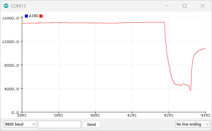
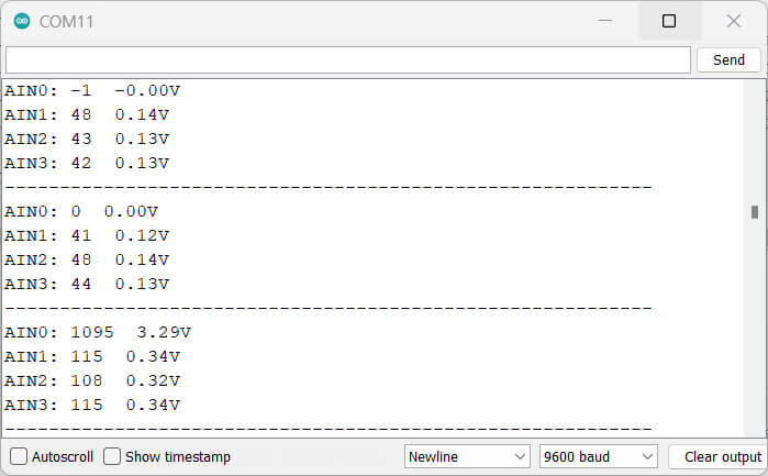
Testing
Check the Voltage of the potentiometer, and see how it changes when rotated pot.
The maximum Voltage you can get is 3.29V


1 Comment
Thank you for your article, but I’d like to leave a little warning: in your examples, you are using the 3.3V source from ESP32 to power the ADS1115. The ADS1115 can run up to 6V, but if you are running your ADS1115 with 5V the I2C interface will run on 5+V as well, meaning your ESP32 will get e.g. 5V on the I2C input pins – you will “overpower” the input pins and destroy them as they take a maximum voltage of 3.3 volts !