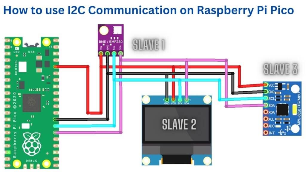
How to use I2C Communication on Raspberry Pi Pico. In this guide, we’ll show you how to use I2C communication on your Raspberry Pi Pico and how to connect it to other I2C devices. This Raspberry pi pico I2C tutorial explains the I2C pins in pico, and configures Master and Slave.
What is I2C Communication?
I2C (Inter-Integrated Circuit) is a serial bus created for connecting devices within a short distance communications between integrated circuits on the same PCB. two-wire, the serial bus used for connecting low-speed devices such as sensors, EEPROMs, and real-time clocks.
Using I2C, you can transmit data at rates 100 kbit/s ((clock 100 kHz – Standard Mode), 400 kbit/s (clock 400 kHz – Fast Mode), 1 Mbit/s (clock 1 MHz – Fast Mode Plus) and 3.4 Mbit/s (clock 3.4 MHz – High Speed Mode).
This may not look much but it is sufficient for interfacing sensors, memories and displays at short distances.
I2C Bus
The Inter-Integrated Circuit bus, or I2C bus, is the two-wire bus used for communication between devices.
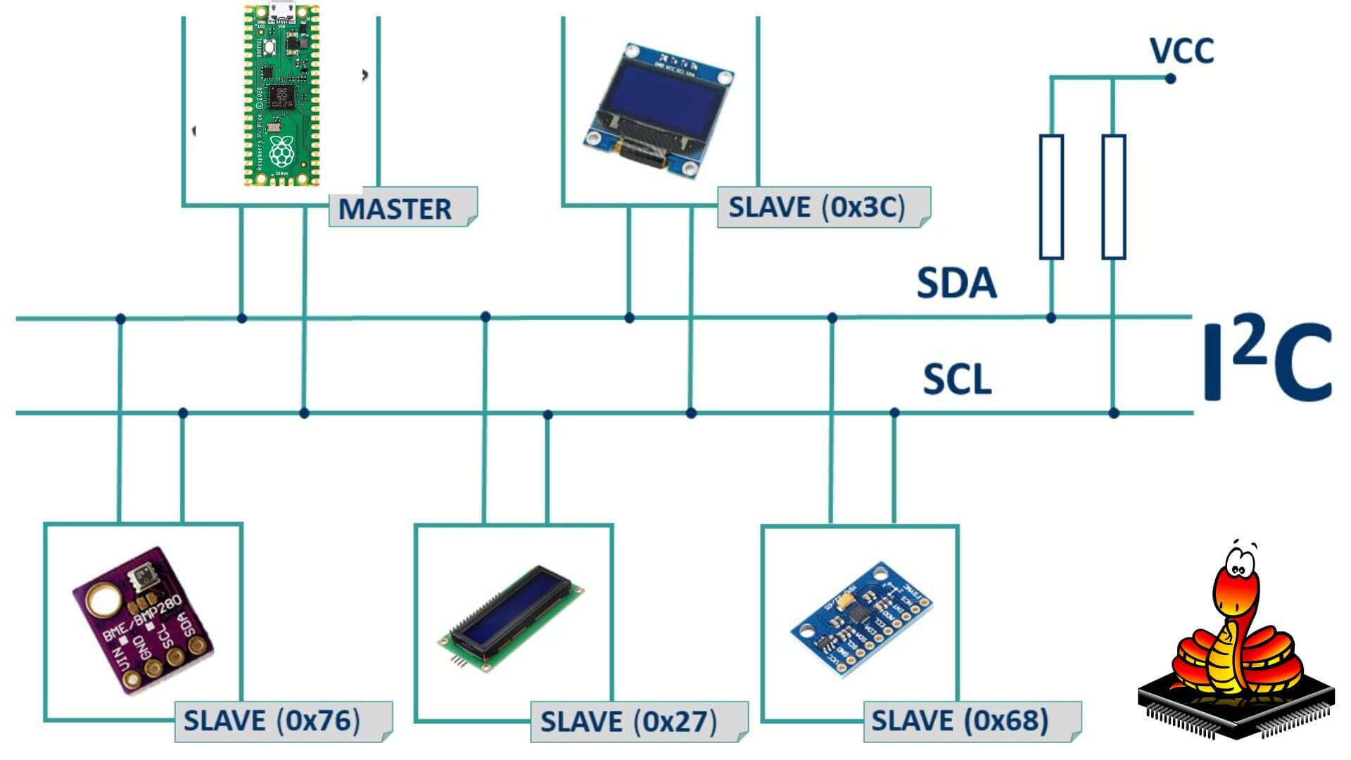
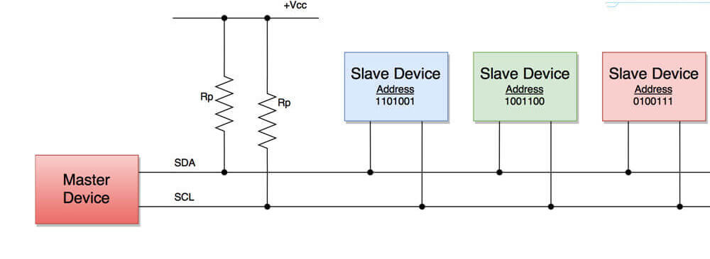
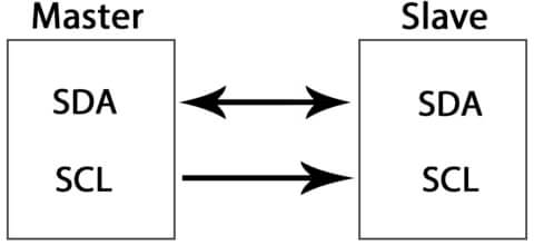
The I2C( Inter-Integrated Circuit ) Bus consists of two wires called the Serial Data (SDA) and the Serial Clock (SCL). Data is transmitted through the SDA line while the SCL line is used to synchronize the devices. The clock is carefully controlled to provide precise timing in communication. All the Sensors/ICs on the I2C network are attached to the same SCL and SDA lines as shown below.
Both bus lines are open-drain drivers, meaning that you need to use pull-up resistors to keep them HIGH.
The I2C network is an advanced level of communication which is support multiple masters and multiple slaves as well. It complies with each slave device connected to the same I2C bus, each slave device is physically having a permanent 7-bit unique address.
The devices connected to the I2C bus are either masters or slaves. At any point in time, there is only one master active on the I2C bus. It controls the SCL clock line and decides what operation is to be done on the SDA data line.
I2C Pins In Raspberry Pi Pico
Raspberry pi pico supports I2C Communication. Take a look at the pinout of Raspberry pi from the tutorial “RASPBERRY PI PICO PINOUT”
The RP2040 microcontroller chip has two I2C controllers. You can access both I2C controllers through the GPIO pins of Raspberry Pi Pico. The following table shows the connection of GPIO pins with both I2C controllers.
| I2C Controller | GPIO Pins |
| I2C0 – SDA | GP0/GP4/GP8/GP12/GP16/GP20 |
| I2C0 – SCL | GP1/GP5/GP9/GP13/GP17/GP21 |
| I2C1 – SDA | GP2/GP6/GP10/GP14/GP18/GP26 |
| I2C1 – SCL | GP3/GP7/GP11/GP15/GP19/GP27 |
For every I2C connection, we have to configure one GPIO pin as SDA and another one as SCL as shown in the example. But before using the I2C controller, we should make sure the GPIO pins are configured in the program.
Features of Raspberry Pi Pico I2C Pins
The Raspberry Pi Pico, which is built with the RP2040 chip, offers the following features for its I2C pins: –
- The device can work in Master Mode or Slave Mode with a custom slave address = 0x055
- The I2C pins have buffers that allow transmit and receive modes.
- The I2C pins have three-speed modes: Standard (0 to 100 Kb/s), Fast(<= 400 Kb/s), and Fast Plus mode (<= 1000 Kb/s).
- The RP2040 chip offers 12 I2C pins that are compatible with many different devices. –
- It can also be used in interrupt and DMA mode
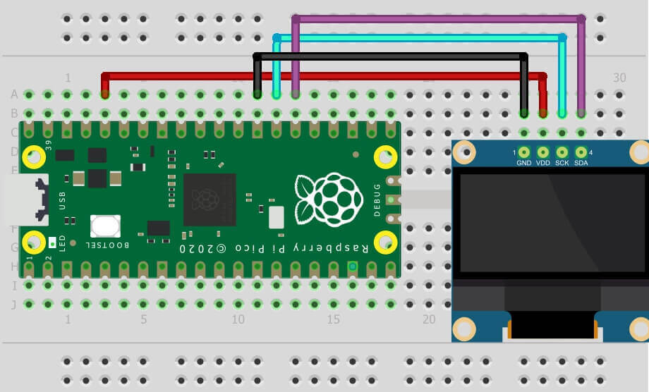
Connect I2C device to Raspberry Pi Pico
I2C Scan Micropython Script
|
1 2 3 4 5 6 7 8 9 10 |
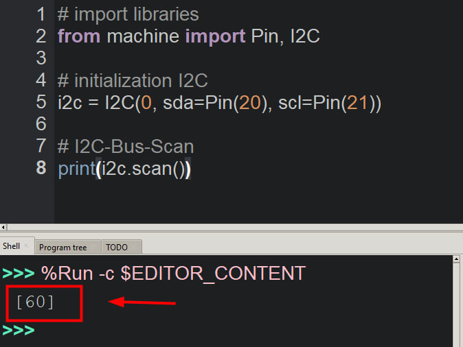
#diyprojectslab.com/raspberry-pi-pico-projects # import libraries from machine import Pin, I2C # initialization I2C i2c = I2C(0, sda=Pin(20), scl=Pin(21)) # I2C-Bus-Scan print(i2c.scan()) |
The I2C bus address of the device at address 0 is 0x3F. The address of the device at address 1 is 0x2E. The I2C bus address of the device at address 2 is 0x39.
Show I2C devices with addresses on Raspberry Pi Pico
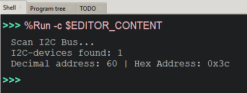
The following micropython code for testing or scanning the I2C bus is more complex. it provides more additional information. For Example, first, the GPIO pins for I2C and the I2C are initialized. After that, then the I2C scan is start and the result is shown on the display.
|
1 2 3 4 5 6 7 8 9 10 11 12 13 14 15 16 17 18 19 20 |
from machine import Pin, I2C # Initialize I2C pins i2c_sda = Pin(20) i2c_scl = Pin(21) # Initialize I2C i2c = I2C(0,sda=i2c_sda,scl=i2c_scl,freq=100000) # I2C-Bus-Scan print('Scan I2C Bus...') devices = i2c.scan() # Output scan result if len(devices) == 0: print('No I2C-device found!') else: print('I2C-devices found:', len(devices)) for device in devices: print('Decimal address:', device, '| Hexa Address:', hex(device)) |
The code will scan the addresses and display them in the IDE shell window.
The actual scan result is an array with the addresses of the devices connected to that I2C bus. The decimal notation of the address is rarely useful for declaring which I2C devices we want to use.
Note: The hexadecimal address is required to initialize the device on the I2C
The I2C Address of the OLED Display is 60 which in Hexadecimal is 0x3C
Raspberry Pi Pico I2C Related Posts
- BME280 With Raspberry Pi Pico W Using MicroPython
- Raspberry Pi Pico W Web Server with BME280 – Mini Weather Station
- Interface 16×2 LCD Display With Raspberry Pi Pico Using Micropython
- How To Connect MPU6050 With Raspberry Pi Pico Tutorial
- How To Use SSD1306 Oled Display With Raspberry Pi Pico


