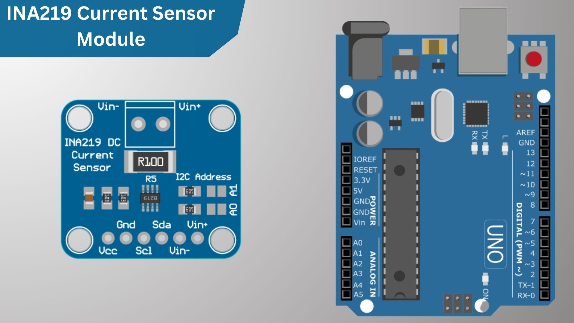
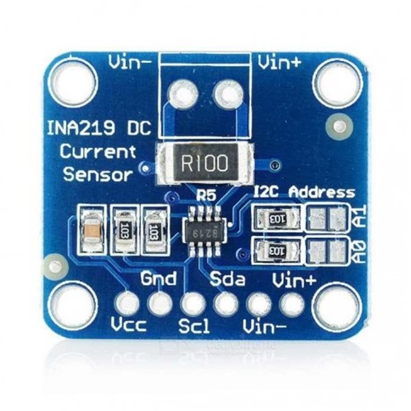
This tutorial will explain how to use DC INA219 Current Sensor Module with Arduino. The INA219 is a Bi-directional DC current sensor module that uses the I2C bus. This module can be used to measure DC currents. module has a built-in shunt resistor and an amplifier.
In this tutorial, we’ll be using an INA219 current sensor module to measure the DC current going through an Arduino board. It is a very useful tool for monitoring the power consumption of your project.
INA219 Current Sensor Module
The INA219 is an IC (Integrated Circuit) developed by Texas Instruments that acts as a high-side current shunt and power monitor. it can be easily used with microcontrollers such as Raspberry Pi, Arduino, ESP32, etc to measure current and power, and it can also sense shunt voltage. It comes equipped with a 0.1-ohm shunt resistor that has a 1% tolerance, for accurate current measurements. The module can measure DC voltage up to +26V.
Download INA219 Datasheet: INA219 Datasheet
This breakout board simplifies power monitoring by utilizing the INA219 chip, enabling precise measurement of high side voltage and DC current draw over I2C with 1% precision
INA219 Schematic
The INA219 module consists of an INA219 chip along with resistors and a capacitor. The capacitor serves as a noise reducer and helps mitigate the effects of unwanted electrical signals.
Let’s go through each component step by step. First, there are two pull-down resistors connected to the address pins A0 and A1. These resistors have a resistance of 10kilo ohms. By default, the device has an address of 40 in hexadecimal.
To change this default address, you can make connections between the address pins (A0 and A1) and either SDA or SCL.
This gives you the ability to choose from a total of 16 different addresses for your device. This is the list of the i2c addresses we can use for each connection made.
| A1 | A0 | Slave Address |
| GND | GND | 1000000 |
| GND | 1000001 | |
| GND | SDA | 1000010 |
| GND | SCL | 1000011 |
| GND | 1000100 | |
| 1000101 | ||
| SDA | 1000110 | |
| SCL | 1000111 | |
| SDA | GND | 1001000 |
| SDA | 1001001 | |
| SDA | SDA | 1001010 |
| SDA | SCL | 1001011 |
| SCL | GND | 1001100 |
| SCL | 1001101 | |
| SCL | SDA | 1001110 |
| SCL | SCL | 1001111 |
Register Address
The INA219 features internal registers that store measurement data and control settings. These registers can be accessed through the I2C interface to configure the chip, trigger measurements, and retrieve measurement results. Here’s an overview:
- Configuration Register (Address = 00h): Controls different settings of the INA219, such as voltage range, gain, resolution, and mode.
- Shunt Voltage Register (Address = 01h): Holds the raw measurement of the shunt voltage.
- Bus Voltage Register (Address = 02h): Stores the raw measurement of the bus voltage.
- Power Register (Address = 03h): Contains the calculated power value.
- Current Register (Address = 04h): Holds the calculated current value.
- Calibration Register (Address = 05h): Sets the calibration value for accurate current and power calculations.
Features and specifications
Features:
- Accurate measurement of current and power consumption.
- Bi-directional current measurement.
- High accuracy with a resolution of 1mA and an accuracy of ±0.5%.
- I2C interface
- Shunt voltage resistor.
- Programmable alert function
Specifications:
- Current measurement: ±3.2A.
- Voltage measurement: Up to +26V.
- Supply voltage: Operates from 3.0V to 5.5V.
- Resolution: 12-bit resolution
- Communication: I2C interface with compatibility for 3.3V and 5V logic levels.
- Operating temperature: -40°C to +85°C.
Pinout of INA219
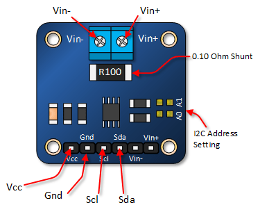
The INA219 sensor module has the following pins:
- VCC: Operating voltage (3.3V to 5.5V)
- GND: Ground pin
- SCL: Clock line for I2C interface.
- SDA: Data line for I2C interface.
- Vin-: Connects to the negative terminal of the voltage supply.
- Vin+: Connects to the positive terminal of the voltage supply.
The INA219 module uses the I2C protocol to communicate with microcontrollers, and each module needs a unique address on the I2C bus. The default address is 0x40, but you can change it if you have multiple INA219 items. To change the address, you must configure the A0 and A1 pins on the INA219 module.
Configuration is as follows:
these pins connect to GND, SDA, and SCL, or are left unconnected (floating). The combination of these connections determines the new address.
For example, if both A0 and A1 are connected to GND, the new address will be 0x40 (same as the default address). If you connect A0 to SDA and A1 to GND, the new address will be 0x48. you’re required to update the address in your code whenever you change the INA219 module’s I2C address so that the microcontroller can communicate with the correct INA219 module on an I2C bus.
How to use DC INA219 Current Sensor with Arduino
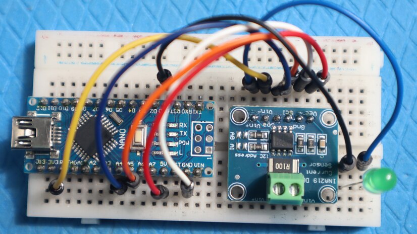
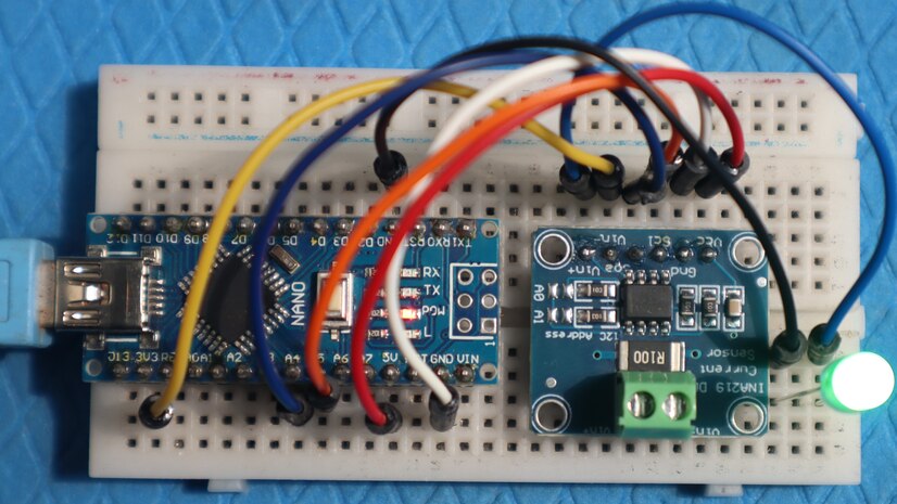
Using the INA219 DC Current Sensor Module with Arduino is straightforward. Here’s a simple Wiring diagram.
Here’s a simple connection diagram for interfacing the INA219 DC Current Sensor Module with an Arduino, external load, and power supply:
| INA219 Pin | Arduino Pin |
|---|---|
| VCC | 5V |
| GND | GND |
| SCL | A5 (SCL) |
| SDA | A4 (SDA) |
| Vin+ (Positive Terminal) | Power Source |
| Vin- (Load) | Load |
Source Code
Below is a sample code that demonstrates how to interface the INA219 Current Sensor module with Arduino. To compile the code, you will need to download and add the Adafruit INA219 library to your Arduino library folder.
|
1 2 3 4 5 6 7 8 9 10 11 12 13 14 15 16 17 18 19 20 21 22 23 24 25 26 27 28 29 30 31 32 33 34 35 36 37 38 39 40 41 42 43 44 45 46 47 48 49 50 51 52 53 54 55 |
#include <Wire.h> #include <Adafruit_INA219.h> Adafruit_INA219 ina219; void setup() { Serial.begin(9600); if (!ina219.begin()) { Serial.println("INA219 not found"); // Print error message if INA219 is not found while (1) { delay(10); } } // To use a slightly lower 32V, 1A range (higher precision on amps): //ina219.setCalibration_32V_1A(); // Or to use a lower 16V, 400mA range (higher precision on volts and amps): ina219.setCalibration_16V_400mA(); // Set calibration for INA219 } void loop() { float shuntVoltage = 0; float busVoltage = 0; float current_mA = 0; float loadVoltage = 0; float power_mW = 0; shuntVoltage = ina219.getShuntVoltage_mV(); // Read shunt voltage busVoltage = ina219.getBusVoltage_V(); // Read bus voltage current_mA = ina219.getCurrent_mA(); // Read current power_mW = ina219.getPower_mW(); // Read power loadVoltage = busVoltage + (shuntVoltage / 1000); // Calculate load voltage Serial.print("Bus Voltage: "); Serial.print(busVoltage); Serial.println(" V"); Serial.print("Shunt Voltage: "); Serial.print(shuntVoltage); Serial.println(" mV"); Serial.print("Load Voltage: "); Serial.print(loadVoltage); Serial.println(" V"); Serial.print("Current: "); Serial.print(current_mA); Serial.println(" mA"); Serial.print("Power: "); Serial.print(power_mW); Serial.println(" mW"); Serial.println(""); delay(2000); // Delay for 2 seconds } |
Working
After uploading the sketch/program to your Arduino, open the serial monitor. Make sure the baud rate is set to 9600.
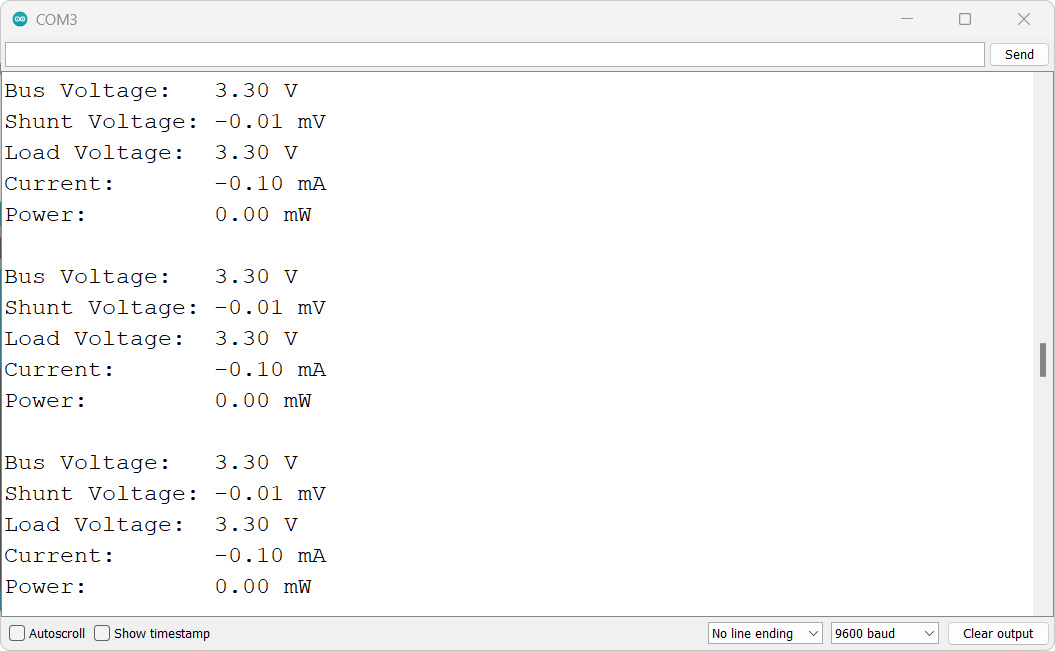
If everything is working correctly, the output in the serial monitor should resemble the screenshot shown above.
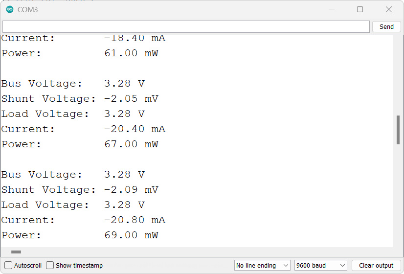
The serial monitor displays measured values such as bus voltage, shunt voltage, load voltage, current, and power at regular intervals.

