In this guide, we’ll go over how to interface the ADS1115 16-bit ADC with ESP8266. We’ll go over the wiring, and then we’ll write a short sketch to output the ADC readings to the Serial Monitor and also the 16×2 display.
For example, you can use ADS1115 to measure temperature, humidity, or other environmental conditions as per your need. You can also use it to measure the voltage of a battery, the current flowing through a resistor, or the power consumption of a device. Recommended Esp8266 Projects You Must Try In 2022!
Required Material
- ESP8266 WiFi Module
- ADS1115 Analog to Digital Converter
- 16×2 I2C Display
- Breadboard and jumper wires
ESP8266 ADC
ESP8266 microcontroller comes with only one ADC (Analog-to-Digital Converter) pin for analog input which means you can use only one analog sensor with ESP8266.
This ADC pin is labeled A0 and is capable of reading analog Values. However, the ESP8266 also has the faculty to interface with external ADCs, such as the ADS1115 16-bit ADC, via its I2C communication interface.
The ESP8266 has a built-in 10-bit ADC (Analog to Digital Converter) which means it can represent analog signals in 1024 discrete steps. it can be used to measure analog signals in the range of only 0 to 1V. ESP8266 ADC can be configured to calculate either single-ended or differential signals.
It’s important the ADC pin on ESP8266 is not 5V tolerant. Accordingly, if you want to monitor voltages overextending 1V this means that any voltage greater than 1V may damage the ESP8266. you just need to use voltage dividers or level shifters to decrease the input voltage to within the range of the ADC pin.
ESP8266 ADC Resolution
The ADC pin has a resolution of 10 bits, which means it can generate values from 0 to 1023.
Code for reading ADC
|
1 2 3 4 5 6 7 8 9 |
void setup() { Serial.begin(9600); } void loop() { Serial.print("ADC Value: "); Serial.println(analogRead(A0)); delay(300); } |
ESP8266 ADC Specifications
Here are the specifications for the ADC (Analog to Digital Converter) on the ESP8266:
- Resolution: 10-bit
- Input voltage range: 0-1V
- Maximum input impedance: 1MΩ
- Sampling rate: up to 10ksps (kilosamples per second)
- Accuracy: ± 2 LSB (Least Significant Bit)
- Linearity error: ± 1 LSB
- Maximum input current: 1mA
- Make ESP8266 Drone (This Drone Can Climb on Wall)
- BMP180 Pressure Sensor Monitor on Adafruit Io with ESP32
- Build ESP8266 Flight Controller For Drone
- ESP8266 Thermal Imager Using AMG8833 Sensor
ADS1115 ADC Module
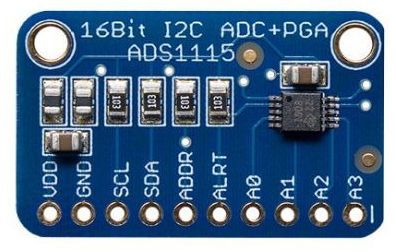
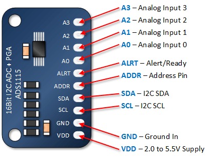
ADS1115 Module Pinout
The ADS1115 module has ten pins as follows:
- VCC: Module power supply
- GND: Ground
- SCL: I2C Clock Pin
- SDA: I2C Data Pin
- ADDR: I2C Address Pin
- ALRT: Data Ready Interrupt
- A0-3: Analog Inputs 0-3
ADS1115 Features
- Resolution: 16-bit
- Input Voltage Range: -0.3V to VDD + 0.3V
- Programmable Data Rate: 8SPS to 860SPS
- Channel AN0 AN1 AN2 AN3 or 2 differential inputs
- Programmable Gain Amplifier: 2/3x, 1x, 2x, 4x, 8x, 16x
- Power Consumption: 150uA (active), 0.2uA (shutdown)
- Voltage Range: 2.0V to 5.5V
- Temperature Range: -40°C to +125°C
- Package Type: MSOP-10
- The external reference voltage (VREF)
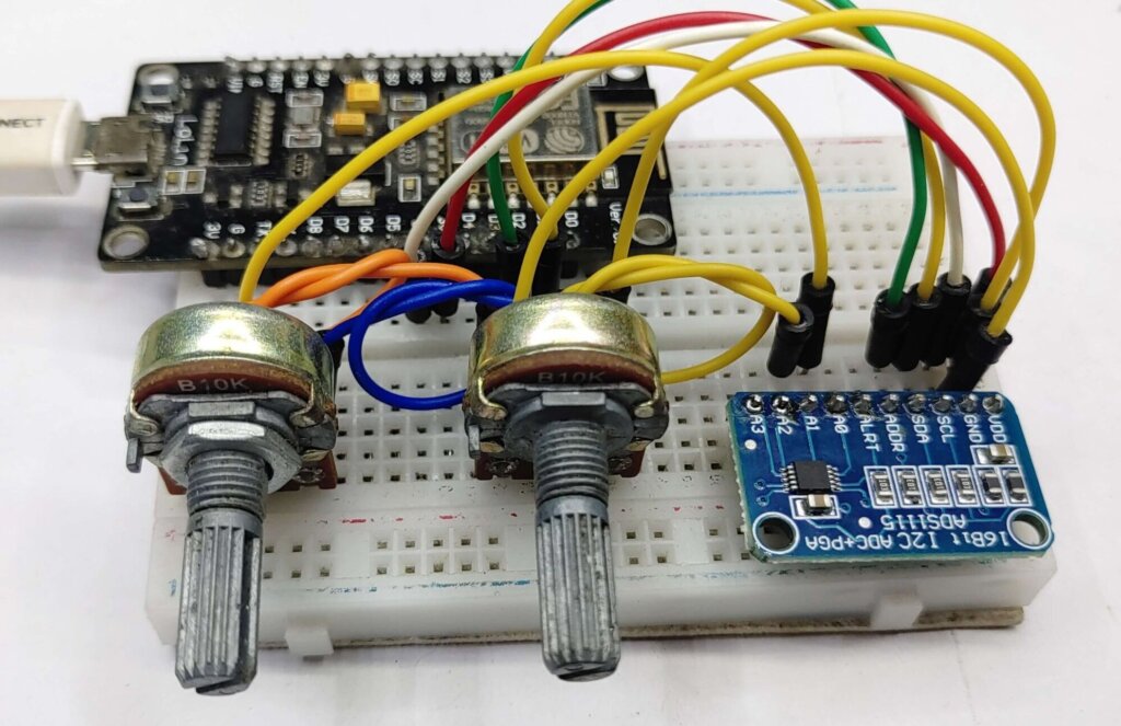
Schematic Diagram – ADS1115 Module with ESP8266
To interface an ADS1115 module with ESP8266, you can follow these steps:
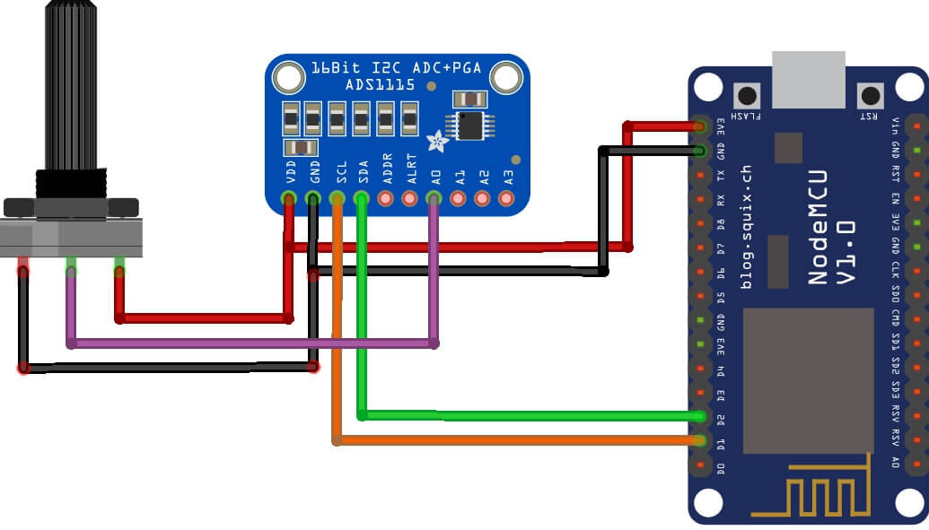
- VDD-> ESP8266 VCC for energy supply;
- GND -> ESP8266 GND;
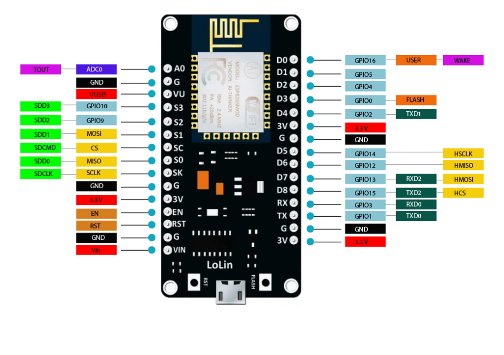
- SCL -> ESP8266 SCL – D1 (I2C protocol);
- SDA -> ESP8266 SDA – D2 (I2C protocol) ;
Code & Libraries
Install ESP8266 to Arduino IDE Getting Started With NodeMCU ESP8266 Arduino IDE | A Beginner’s Guide
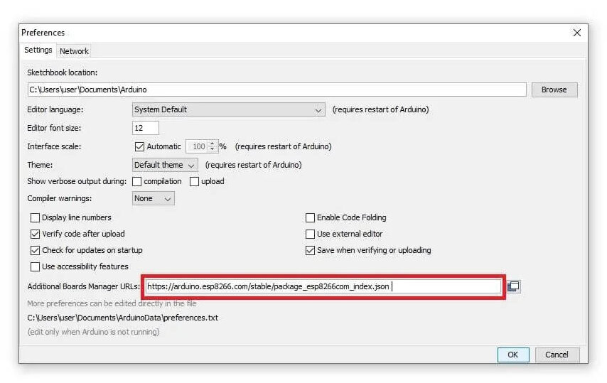
- Open the Arduino IDE and go to File -> Preferences.
- In the Additional Boards Manager URLs field, paste the following URL: http://arduino.esp8266.com/stable/package_esp8266com_index.json
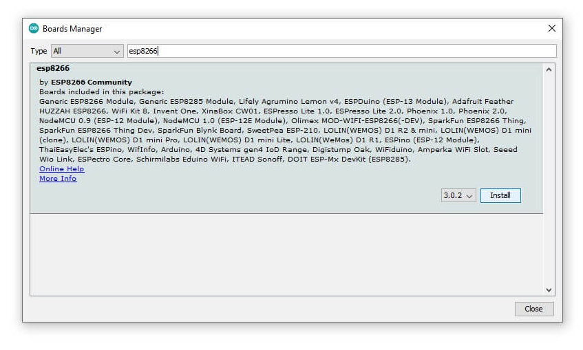
- Now go to Tools -> Board -> Boards Manager.
- In the Boards Manager, search “esp8266” and select “esp8266 by ESP8266 Community”
- Click and install it.
- Now, go to Tools -> Board and select the ESP8266 12e board.
Install Libraries
Install the Adafruit ADS1X15 library in the Arduino IDE to be able to use the ADS1115 module with the ESP8266.
Copy the following code & upload it to the ESP8266 board.
|
1 2 3 4 5 6 7 8 9 10 11 12 13 14 15 16 17 18 19 20 21 22 23 24 25 26 27 28 29 30 31 32 33 34 35 36 |
#include "ADS1X15.h" ADS1115 ADS(0x48); void setup() { Serial.begin(115200); Serial.println("Hello! DIY PROJECTS LAB"); Serial.println(__FILE__); Serial.print("ADS1X15_LIB_VERSION: "); Serial.println(ADS1X15_LIB_VERSION); ADS.begin(); } void loop() { ADS.setGain(0); int16_t val_0 = ADS.readADC(0); int16_t val_1 = ADS.readADC(1); int16_t val_2 = ADS.readADC(2); int16_t val_3 = ADS.readADC(3); float f = ADS.toVoltage(1); // voltage factor Serial.print("\tADC0: "); Serial.print(val_0); Serial.print('\t'); Serial.println(val_0 * f, 3); Serial.print("\tADC1: "); Serial.print(val_1); Serial.print('\t'); Serial.println(val_1 * f, 3); Serial.print("\tADC2: "); Serial.print(val_2); Serial.print('\t'); Serial.println(val_2 * f, 3); Serial.print("\tADC3: "); Serial.print(val_3); Serial.print('\t'); Serial.println(val_3 * f, 3); Serial.println(); delay(1000); } |
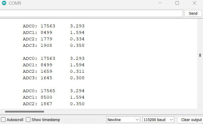
Result
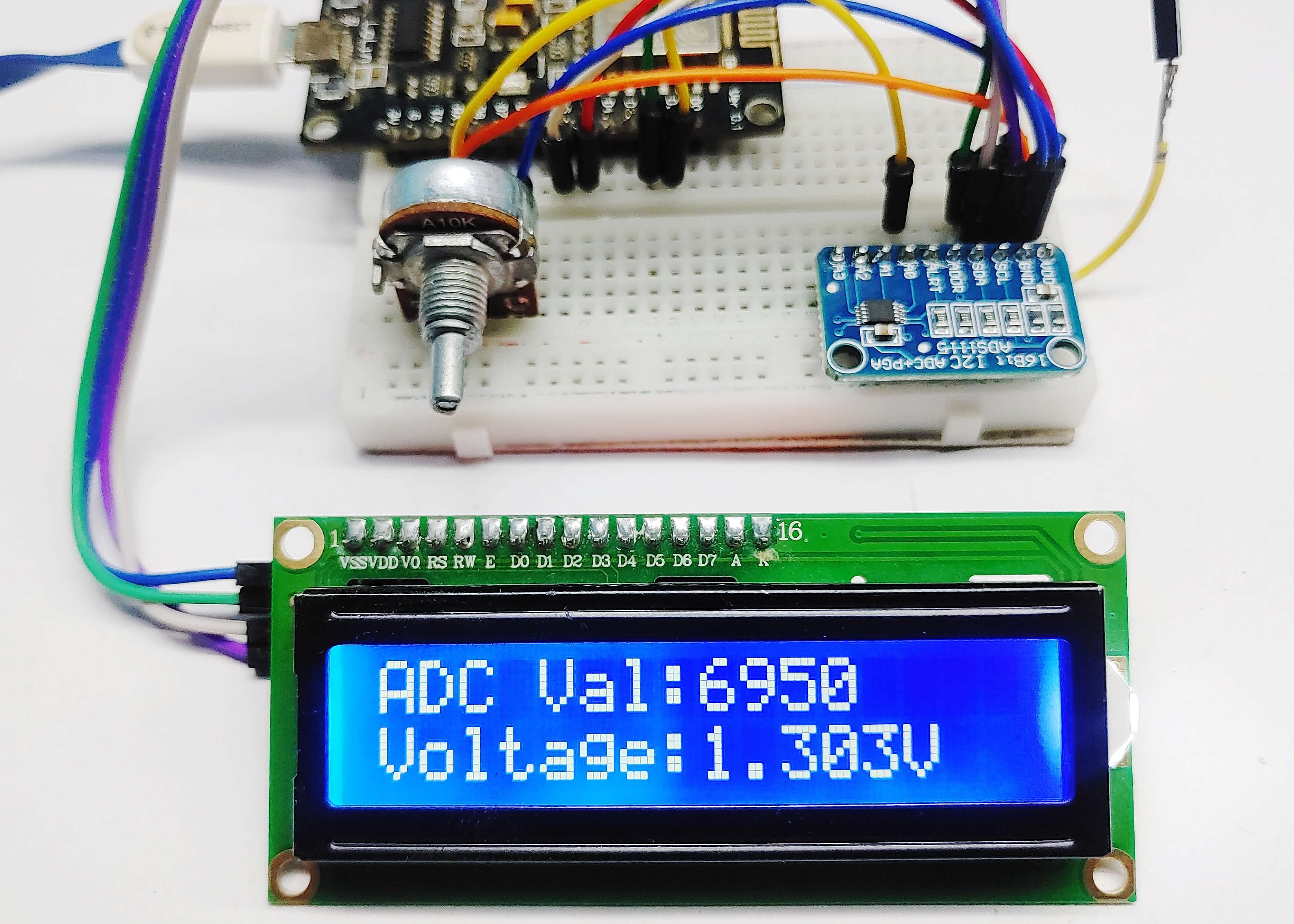
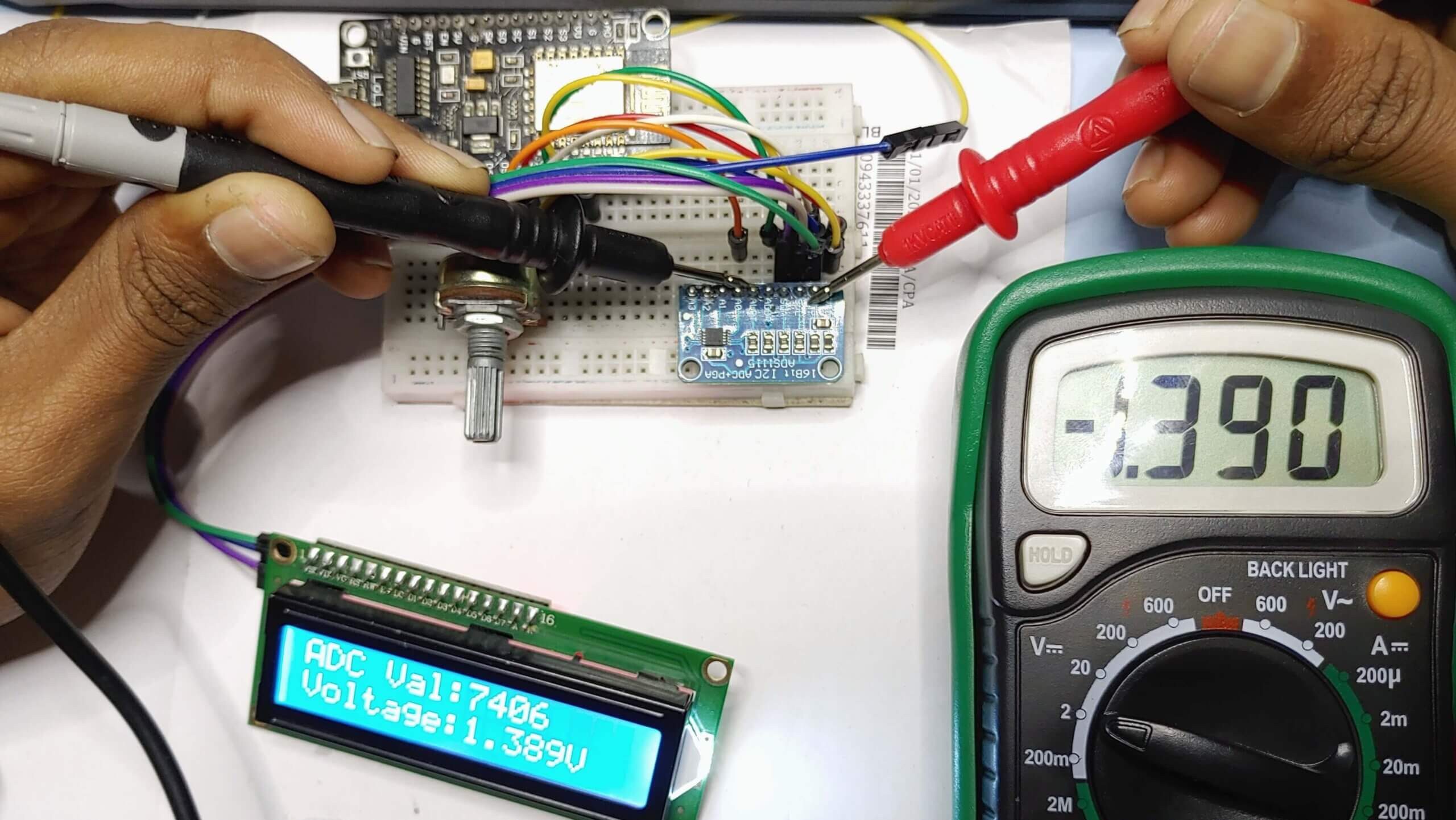
Interface ADS1115 Module & 16×2 I2C Display with ESP8266
Source Code ADS1115 Module & 16×2 I2C Display with ESP8266
|
1 2 3 4 5 6 7 8 9 10 11 12 13 14 15 16 17 18 19 20 21 22 23 24 25 26 27 28 29 30 31 32 33 34 35 36 37 38 39 40 41 42 43 44 45 46 47 48 |
#include "ADS1X15.h" #include <LiquidCrystal_I2C.h> LiquidCrystal_I2C lcd(0x27, 16, 2); ADS1115 ADS(0x48); void setup() { Serial.begin(115200); Serial.println(__FILE__); Serial.print("ADS1X15_LIB_VERSION: "); Serial.println(ADS1X15_LIB_VERSION); lcd.init(); lcd.backlight(); ADS.begin(); } void loop() { ADS.setGain(0); int16_t val_0 = ADS.readADC(0); int16_t val_1 = ADS.readADC(1); int16_t val_2 = ADS.readADC(2); int16_t val_3 = ADS.readADC(3); float f = ADS.toVoltage(1); // voltage factor Serial.print("\tADC0: "); Serial.print(val_0); Serial.print('\t'); Serial.println(val_0 * f, 3); Serial.print("\tADC1: "); Serial.print(val_1); Serial.print('\t'); Serial.println(val_1 * f, 3); Serial.print("\tADC2: "); Serial.print(val_2); Serial.print('\t'); Serial.println(val_2 * f, 3); Serial.print("\tADC3: "); Serial.print(val_3); Serial.print('\t'); Serial.println(val_3 * f, 3); Serial.println(); lcd.clear(); lcd.setCursor(0, 0); lcd.print("ADC Val:"); lcd.print(val_0); lcd.setCursor(0, 1); lcd.print("Voltage:"); lcd.print(val_0 * f, 3); lcd.print("V"); delay(1000); } |
Working

