In this tutorial, we will be using the PM2.5 dust smoke particle sensor with Arduino. This sensor is used to detect the presence of particles in the air, such as dust, and smoke. The sensor outputs a digital signal that can be read by an Arduino microcontroller.
We will be using the Arduino to read this voltage and convert it to a dust concentration in units of μg/m3.
NextPCB
Thanks to NextPCB’s help, our project succeeded! Check out their website for great discounts on high-quality, reliable PCBs starting at $1.9 and multilayer boards from $6.9. Plus, get free PCB assembly for 5 boards!
Required Components:
- Arduino board
- PM2.5 dust smoke particle sensor
- Jumper wires
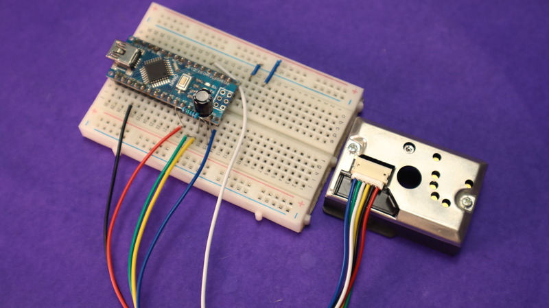
- Breadboard
PM2.5 dust smoke particle sensor
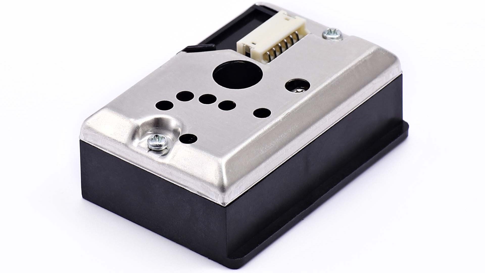
PM2.5 GP2Y1010AU0F is an optical air quality sensor, designed to sense dust particles. An infrared emitter and a phototransistor are diagonally placed into this device, to allow it to detect the reflected light of dust in the air. It is especially effective in detecting fine particles like cigarette smoke and is broadly used in air purifier units.
This sensor is known for very low power consumption (20mA max, 11mA typical), You can power it with up to 7 volts of direct current (DC). When it senses dust, it releases a voltage that shows how much dust it’s spotted.
For every 0.1 milligrams of dust per cubic meter of air, the sensor’s voltage changes by 0.5 volts. 0.5V/0.1mg/m3.
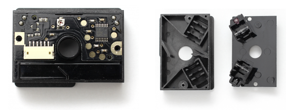
Internal Structure Of PM2.5 Dust Smoke Particle Sensor
Inside, I found an IR LED and an IR detector not facing each other but directed at a small hole. The LED pulses, lighting up dust/smoke passing through the hole, are detected by the IR sensor.
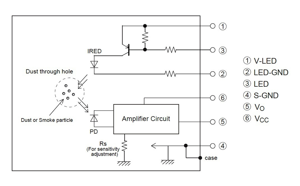
The amplified signal appears on the Vo pin. A PNP transistor drives the LED, requiring grounding of its base via pin 3 for activation.
Sensitivity, which is basically the gain of the amplifier, can be modified from a small PCB potentiometer, which is shown via a small hole in the case.
Schematic Diagram PM2.5 Dust Smoke Particle Sensor
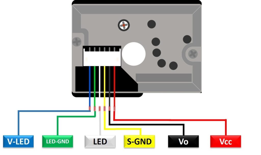
Pinout Of PM2.5 Dust Smoke Sensor
The GP2Y1014AU0F PM2.5 Optical Dust Sensor pinout generally contains:
| S. NO. | Pin Name | Pin Description |
|---|---|---|
| 1 | V-LED | LED VCC Pin. Connects to 5V via a 150Ω Resistor |
| 2 | LED-GND | LED Ground Pin. Connects to GND |
| 3 | LED | Toggles LED On/Off. Connect to any digital pin on the Arduino |
| 4 | S-GND | Sensor Ground Pin. Connects to Arduino’s GND |
| 5 | VOUT | Sensor Analog Output Pin. Connects to any Analog Pin |
| 6 | VCC | Positive Supply Pin. Connects to Arduino’s 5V |
Features & Specification
- Low Power: Uses a maximum of 20mA
- Voltage Range: Operates typically between 4.5V to 5.5V
- Detects Tiny Particles: Can detect particles as small as 0.5µm
- Dust Density Range: Detects up to 580 µg/m3
- Quick Response: Sensing time under 1 second
- Sensitivity: Offers 0.5V per 100 µg/m3 sensitivity
- Temperature Range: Works between -10°C to +65°C
- Compact Size: Dimensions of 1.81 x 1.18 x 0.69 inches (46.0 x 30.0 x 17.6 mm)
- Single Pulse Detection: Detects dust with a single pulse
- Differentiates Smoke and House Dust: Can tell smoke from household dust
- Compliant: Lead-free and follows RoHS directive
Applications
- Air Quality Monitoring
- Indoor Spaces
- Ventilation Systems
- Automotive
- Healthcare
- R&D and IoT
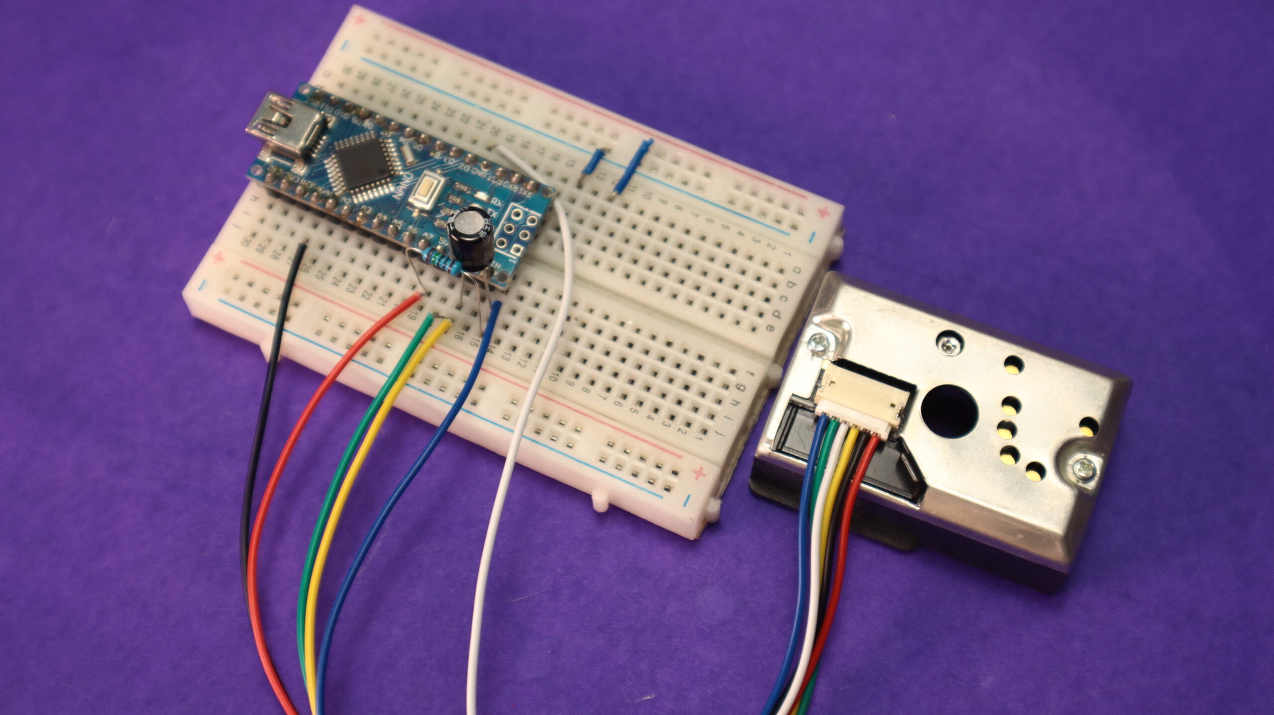
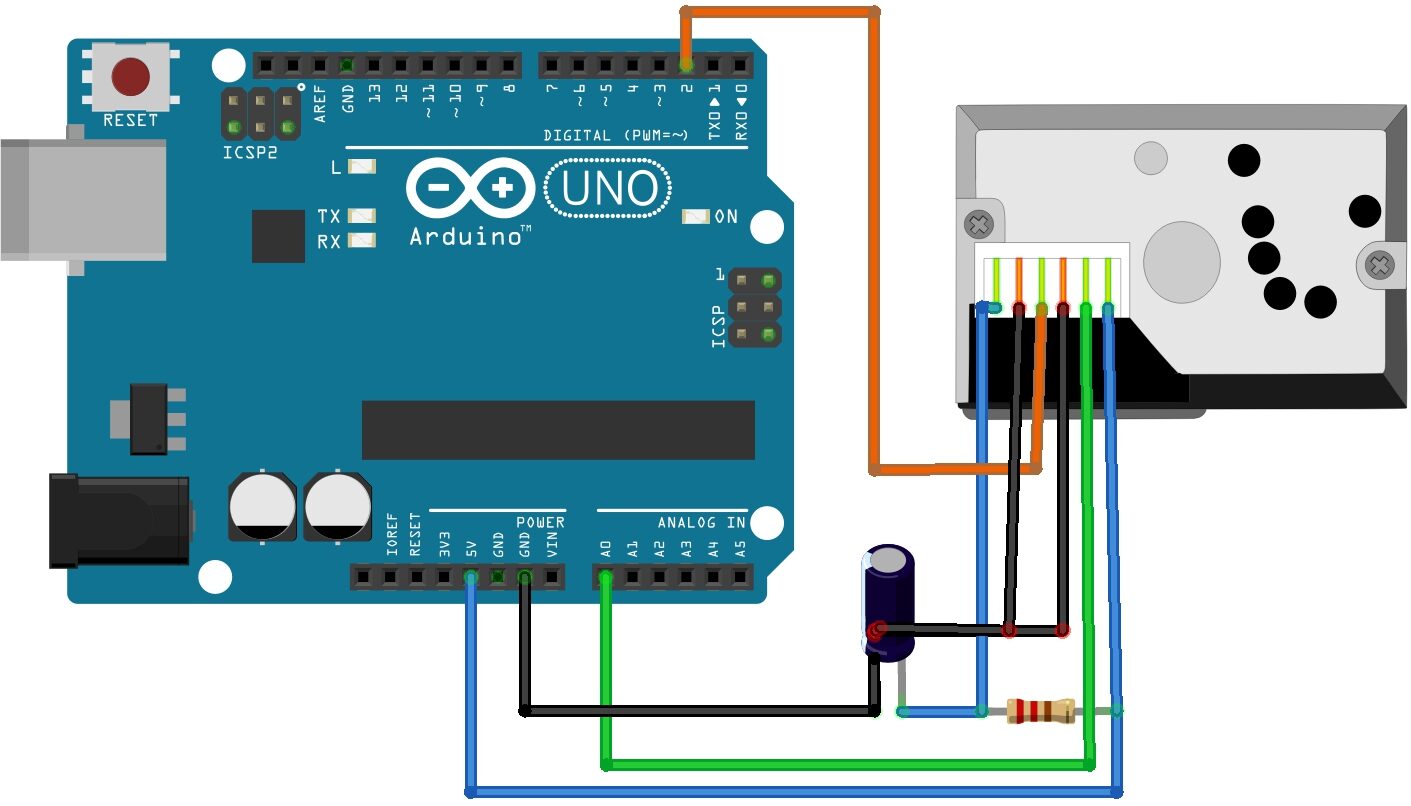
| Sensor Pin | Connection | Arduino Pin |
|---|---|---|
| VCC (Pin 1) | 5V | 5V |
| LED-GND (Pin 2) | GND | GND |
| LED (Pin 3) | Digital Pin | Any Digital Pin |
| S-GND (Pin 4) | GND | GND |
| VOUT (Pin 5) | Analog Pin | Any Analog Pin |
| VCC (Pin 6) | 5V | 5V |
Source Code
|
1 2 3 4 5 6 7 8 9 10 11 12 13 14 15 16 17 18 19 20 21 22 23 24 25 26 27 28 29 30 31 32 33 34 35 36 37 38 39 40 41 42 43 |
/* Standalone Sketch for Arduino UNO and Dust Sensor */ int measurePin = A0; // Connect dust sensor to Arduino A0 pin int ledPower = 2; // Connect dust sensor LED driver pin to Arduino D2 int samplingTime = 280; int deltaTime = 40; int sleepTime = 9680; float voMeasured = 0; float calcVoltage = 0; float dustDensity = 0; void setup() { Serial.begin(9600); pinMode(ledPower, OUTPUT); } void loop() { digitalWrite(ledPower, LOW); // Turn on the LED delayMicroseconds(samplingTime); voMeasured = analogRead(measurePin); // Read dust value delayMicroseconds(deltaTime); digitalWrite(ledPower, HIGH); // Turn off the LED delayMicroseconds(sleepTime); // Map 0-5V to 0-1023 integer values and recover voltage calcVoltage = voMeasured * (5.0 / 1024.0); // Linear equation derived from http://www.howmuchsnow.com/arduino/airquality/ // Chris Nafis (c) 2012 dustDensity = 170 * calcVoltage - 0.1; Serial.print("Dust Density: "); Serial.print(dustDensity); Serial.println(" ug/m3"); // Output in ug/m3 delay(1000); } |
Upload the Code:
- Connect the Arduino to your computer using a USB cable.
- Select the board and port in the Arduino IDE Software.
- Upload the code to the Arduino board.
Monitor Readings:
- After uploading the code Open the Serial Monitor in the Arduino IDE (Tools > Serial Monitor).
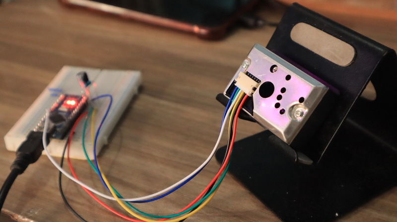
- You should start seeing readings from the sensor shown on the monitor.
Note: This is a basic example and may require adjustments depending on the sensor and specifications. Always refer to the sensor’s datasheet for accurate interfacing.

1 Comment
Very well written and nicely explained