Hey everyone, it’s Rabindra here, and I’m excited to share another project with you today. We will make an IoT-based variable Programmable digital Power Supply using ESP8266. Unlike standard designs with potentiometers, which can be unreliable and non-linear, we’re aiming for accuracy. So today I will show you a boring, theoretical but accurate method for making a digital power supply, but its accuracy makes it worth the effort. Let’s get started!
Required Material
-
- WeMos D1 (ESP8266)
- ADS1115 ADC
- 16×2 LCD Module
- Rotary Encoder Module
- LM358 IC (or any good op-amp for DC designs)
- MP1584 Step-Down Converter
- Capacitors and Resistor
- jumper wire
- Terminal Block
- Zero PCB
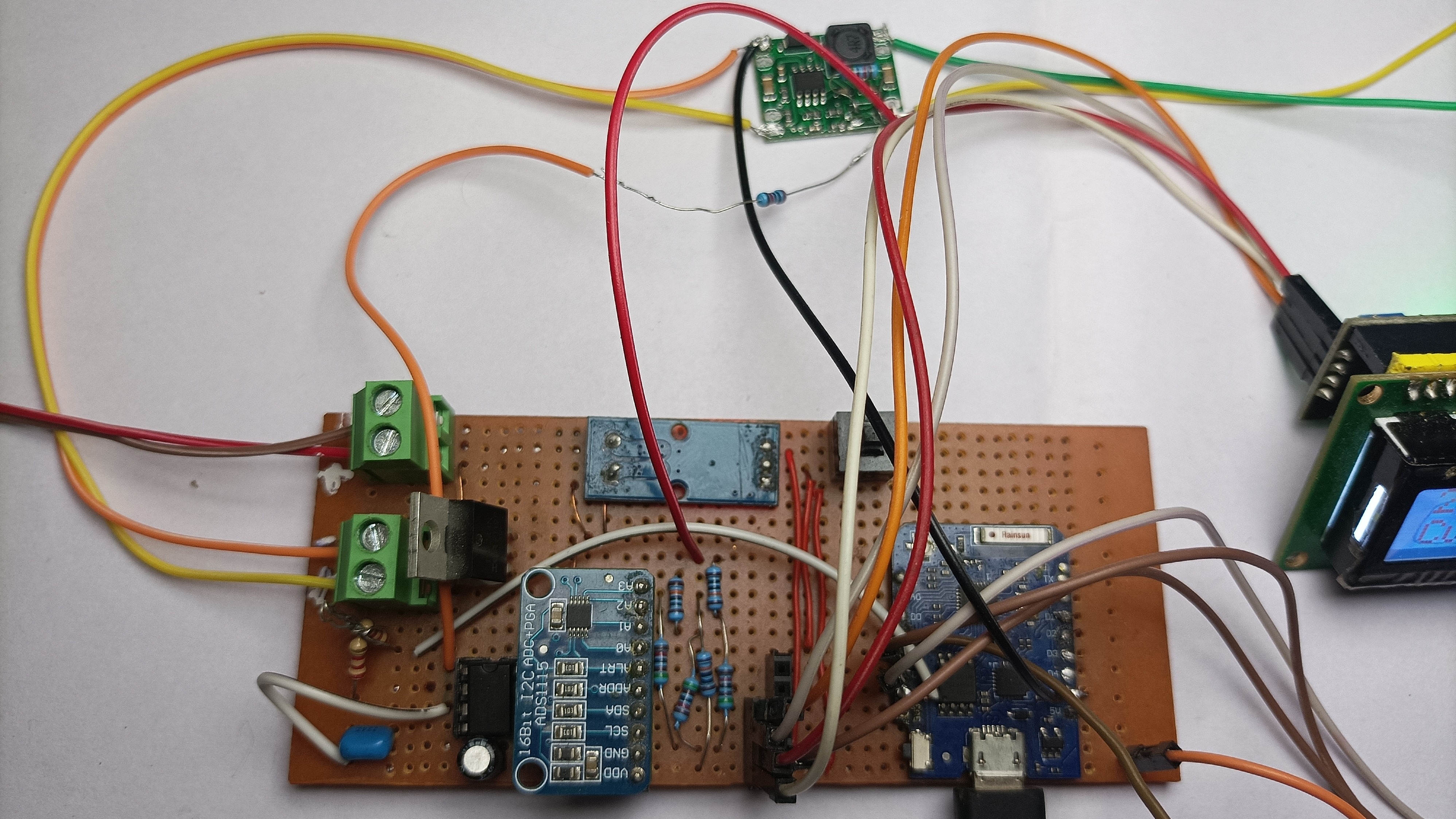
So let me explain the outline before going into the details. Our system has a pre-built buck converter, a circuit featuring an ESP8266, a 16×2 LCD, and a rotary encoder for voltage adjustment.
This setup offers the additional benefit of reduced electromagnetic (EMC) issues. Also, we’ve integrated a hall effect-based current sensor and a 16-bit ADC for accurate measurements. You can adjust the voltage using physical input method controls or via a web server. In fact (we can even implement this power supply as a slave device to which we can send data and configure the voltage).
Next, we’ll show how to control the output voltage of a DC-DC converter with a microcontroller. We’ll cover two methods:
- Using digital potentiometer.
- Injecting voltage using a DAC.
We’ll discuss the pros and cons of each method and explain why we prefer the second option. and eventually, we would discuss the errors, since we’re using open-loop control, we need to make a calibration test, which I’d also explain, Additionally, this project uses WebSockets for real-time data transfer over WiFi, you can refer to our earlier project __ for this.
Nowadays, there are many integrated circuits (ICs) available that offer similar outcomes. However, this project provides us the flexibility to change voltage without the need for it
Salient Features
- Digital Control of output voltage using websockets over wifi
- Digital Voltage and current reading, using 16 bit-ADC, over wifi which is updated
Theory
So, we’re using a ready-made DC-to-DC converter module because it’s easier. If we want to change things later, like upgrading power or trying a different setup, we’d have to recalibrate otherwise. Before we buy one DC-DC converter, need to know certain parameters which are common for almost every DC-DC converter namely:-
- Feedback Voltage
- Working voltage range
To change the voltage of the DC-DC converter, we just adjust some feedback resistors. In simple terms, the controller will do everything it can (i.e. change output voltage ), to maintain the feedback voltage defined in the datasheet at the feedback pin of the controller. Using this concept there are two major ways to change the voltage
- The Easy Method
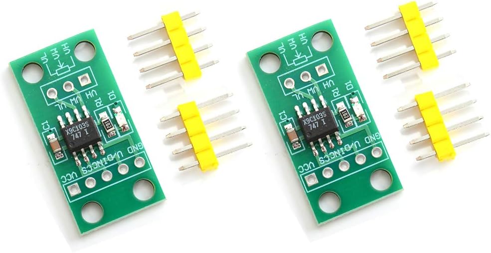
This method uses a digital potentiometer, a circuit that allows us to adjust the wiper position of a voltage divider, simulating a traditional potentiometer. While this method is straightforward to implement, there are many cons.
Firstly, the voltage resolution is usually small, and higher-resolution ones are quite expensive. Additionally, these integrated circuits (ICs) manufacturing processes can introduce distortion. they’re still commonly used in TVs, audio systems, and similar devices to adjust settings like volume and gain.
2. “The accurate but lengthy method“
Even if it seems tough to complete an article post, I urge you to stick with the theory before deciding to make any judgments. This method is based on basic Kirchoff’s law. I’ll share with you the specific design details and calculations needed.
In simple terms, we’re just adding a DC voltage bias voltage to the feedback pin of the DC-DC converter. It’s not too tough to set up on any microcontroller using either a PWM signal or a DAC output. I’ll explain both options clearly.
Here are the main benefits of using this method
- High accuracy in resolution, especially compared to digital potentiometers.
- Low implementation cost, requiring only an additional resistor and capacitor after calibration.
There are many types of DC-DC converter modules available at affordable prices in the market. Here we discuss controlling the output voltage using an external apparatus, such as a PWM signal from a microcontroller like an ESP8266, Arduino, or Raspberry Pi.
How the Output Voltage is Controlled by a Potentiometer
A potentiometer, or “pot,” functions as a variable resistor and is connected between OUT+ and the Feedback pin. A fixed resistor is also connected between the Feedback pin and the Ground.
The “Feedback” pin is the negative input of the operational amplifier. The positive input of this amplifier is connected to a reference voltage, normally between 0.8V.
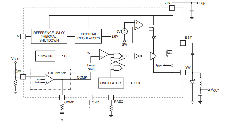
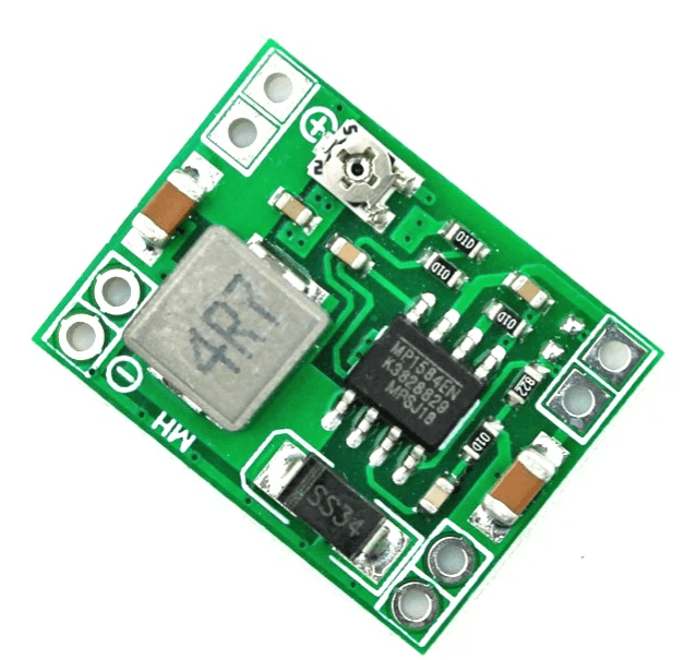
Technical Details of the MP1584 Module
The MP1584 module is based on the MP1584 integrated circuit. Here is the first general description paragraph from the MP1584 Datasheet.
The MP1584 is a high-frequency step-down switching regulator featuring an integrated internal high-side high voltage power MOSFET. It is capable of driving a 3A load with high efficiency of output current and uses current mode control for fast loop response and straightforward compensation
The datasheet looks like this.
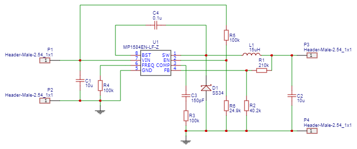
Circuit Diagram of MP1584 Module
How do we control MP1584 buck converters with a Microcontroller
Most buck converters have a voltage divider between the output and a “FB” comparator input set at a fixed voltage (usually 1.2V or 0.8V; check the Datasheet).
By injecting a limited current into the voltage divider, you can adjust the output voltage. For example, using a PWM output, a low-pass filter, and a 100k resistor, you can control the buck converter’s output from 5.5V (PWM at 0) down to ~0.8V (PWM at 255).
By changing the resistor values, you can control even higher voltages.
R2 which is the top resistor for a feedback voltage:
|
1 |
Vout = Vref *(1 + R2/R1) |
Understanding the MP1584 Feedback Control
The MP1584 step-down converter changes its output voltage based on the voltage at its feedback (FB) pin.
We aim to put a voltage at the node via a resistor R3, this voltage can be discovered using either a DAC i.e. using a digital-to-analog converter, but not all microcontrollers have a DAC.
we are going with an even simpler method i.e we are generating a 1khz PWM signal and using a low pass filter whose RC period is 10 times more than the input PWM signal, we effectively create a passive integrator and then use a driving stage created using lm358 IC this voltage is fed to the node via a resistor R3 via a resistor.
If we solve using KIrchoffs law at the node we will get an equation relating the node voltage to the output voltage, the relation is inverse and I’ll prove it later.
| Method | Steps |
|---|---|
| Using DAC | 1. Connect a resistor between the FB pin of the MP1584 and the DAC output of the MCU |
| 2. The DAC voltage controls the buck converter’s output by adjusting the current through the resistor. | |
| Using PWM | 1. Generate a PWM signal from the MCU |
| 2. Filter the PWM signal with an RC filter to create a constant analog voltage. | |
| 3. Connect a resistor between the FB pin of the MP1584 and the output of the RC filter. | |
| 4. The filtered PWM voltage controls the buck converter’s output by adjusting the current through the resistor. |
First, we need to determine the feedback voltage of the DC-DC converter and understand the working voltage range of our voltage driver. Additionally, it’s important to identify the maximum output voltage of the DAC output, generally equal to the operating voltage of the MCU.
Next, we calculate three resistor values: R1, R2, and R3. These values can be calculated using Kirchhoff’s current law at the junction of the feedback pin.
After the calculations, we can rearrange the equation and observe that the output voltage is directly proportional to the set voltage (I apologize for any confusion caused by the term “set voltage” used in the code, which refers to the voltage set by the user but here it means the voltage injected)
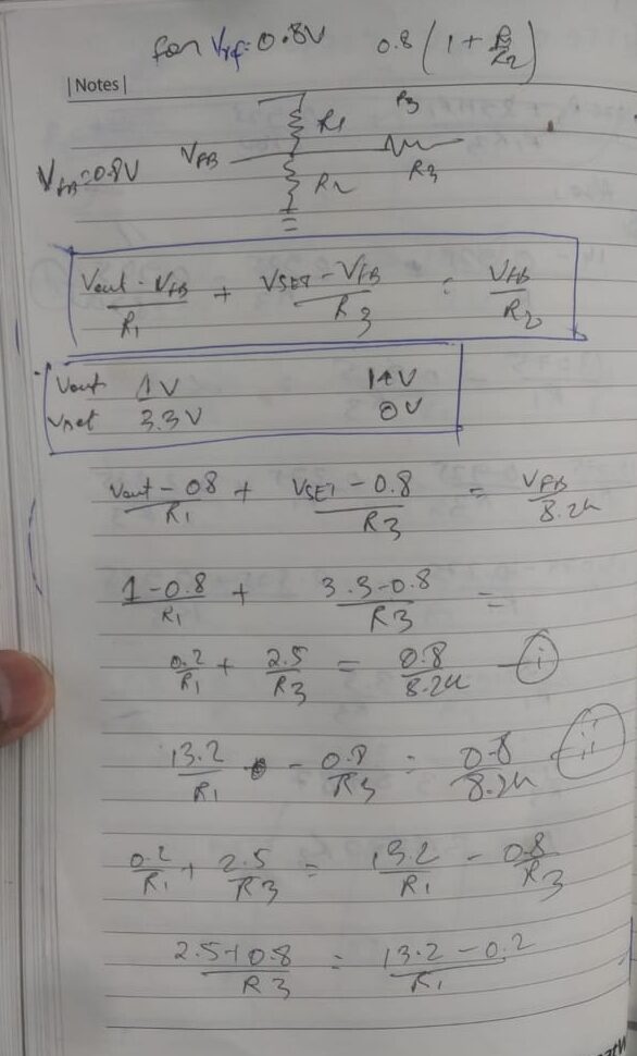
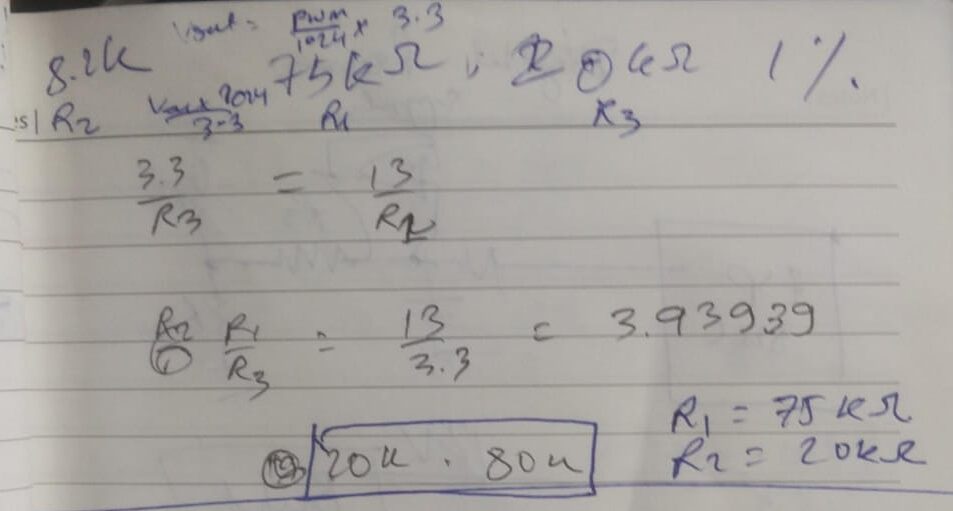
Here I put my calculations for reference, don’t worry we will soon make a calculator to make the process a lot easier but to learn how this works it’s better to go with my example
The following are the assumptions for my example
- Feedback voltage = 0.8V
- R1 was removed and R2 was measured to be 8.2K
- Applying Kirchhoff’s current law at the node of the three resistors we have the equation in the box below
- At3.3V given by the DAC, our regulator should give out 1V
- At 0V given by the DAC, our regulator should output 14V (They are inversely related !) and using R2 as 8.2K
After calculations, you can see that for the given conditions we have a relation of R1 = 3.9393 * R3, and we used approximately 75k and 20k resistors.
Resistor Calculations
Here are my calculations for reference. Don't worry, we will soon create a calculator to simplify the process. However, for now, it's beneficial to understand the workings through my example.
Assumptions and Given Values:
- Feedback voltage (Vfb): 0.8V
- R1: To be determined
- R2: 8.2kΩ (8200Ω)
- Output Voltage at DAC = 3.3V: Vout = 1V
- Output Voltage at DAC = 0V: Vout = 14V
Using Kirchhoff's Current Law (KCL):
General Equation for the Voltage Regulator:
Rearrange to solve for R1:
At DAC = 3.3V (Vout = 1V):
1 = 0.8 + 0.8 (R1/8200)
1 - 0.8 = 0.8 (R1/8200)
0.2 = 0.8 (R1/8200)
R1/8200 = 0.2/0.8
R1/8200 = 0.25
R1 = 0.25 * 8200
R1 = 2050 Ω
At DAC = 0V (Vout = 14V):
14 = 0.8 + 0.8 (R3/8200)
14 - 0.8 = 0.8 (R3/8200)
13.2 = 0.8 (R3/8200)
R3/8200 = 13.2/0.8
R3/8200 = 16.5
R3 = 16.5 * 8200
R3 = 135300 Ω
Relating R1 and R3:
R3 = 135300 Ω
R1/R3 = 2050/135300
R1/R3 ≈ 0.0151
From this, we see R1 ≈ 0.0151 × R3, which conflicts with the earlier derived relationship. Reviewing the above steps suggests a potential error. To correct, let's establish:
Ideal Resistor Values:
From earlier: R1 = 75kΩ and R3 = 20kΩ
75k = 3.9393 × 20k Ω
Conclusion:
Correct calculations should consistently align with R1 ≈ 3.9393 × R3, matching our approximated resistor choices R1 = 75kΩ and R3 = 20kΩ.
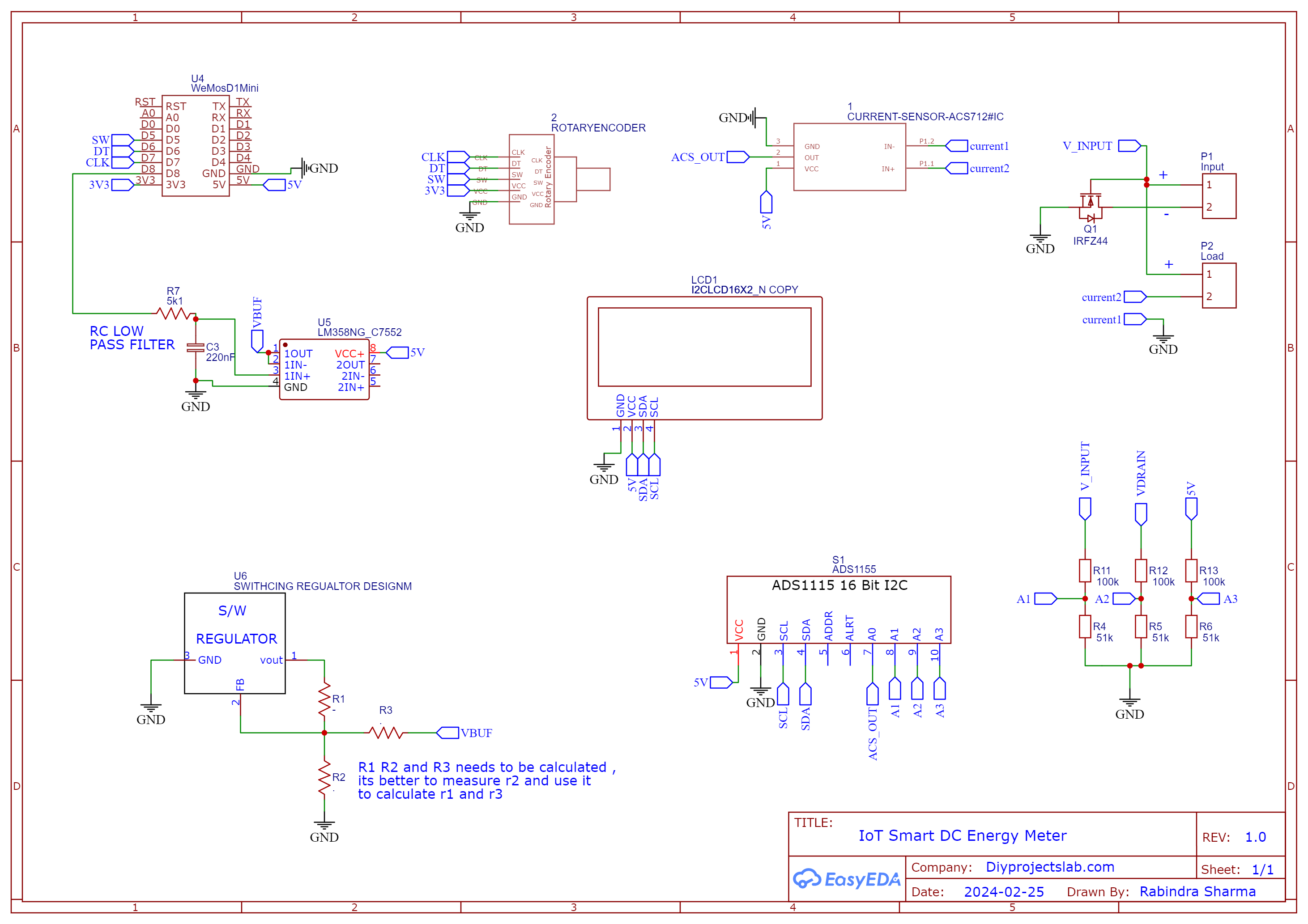
Circuit Diagram – Programmable Digital Power Supply With ESP8266
Connection Guide
| Component | WeMos D1 Pin | Notes |
|---|---|---|
| Rotary Encoder (CLK) | D7 | CLK pin to D7 |
| Rotary Encoder (DT) | D6 | DT pin to D6 |
| Rotary Encoder (SW) | D5 | SW pin to D5 |
| LCD Module (I2C SDA) | D2 | Connect using I2C |
| LCD Module (I2C SCL) | D1 | Connect using I2C |
| ADS1115 ADC (I2C SDA) | D2 | Connect using I2C |
| ADS1115 ADC (I2C SCL) | D1 | Connect using I2C |
| MP1584 Step-Down Converter | N/A | Set up according to the datasheet |
| IR2104 Half Bridge Driver | N/A | Set up according to the schematics |
| LM358 IC (Voltage Feedback Buffer) | N/A | Use as a voltage feedback buffer |
Confirm all connections are correct before powering up the system.
Calibration
It’s most probable that this won’t perform as it should because of various factors, like tolerance of resistance and other factors, so there are two solutions we could have used a closed loop control but that’s not very economical, so I went with open loop control.
So after you have tested that the control is working and the errors are like 10-20% of the max supply range, then you can start calibration, this process varies from one switching controller to another and has to be done manually and is boring but it’s worth the pain,
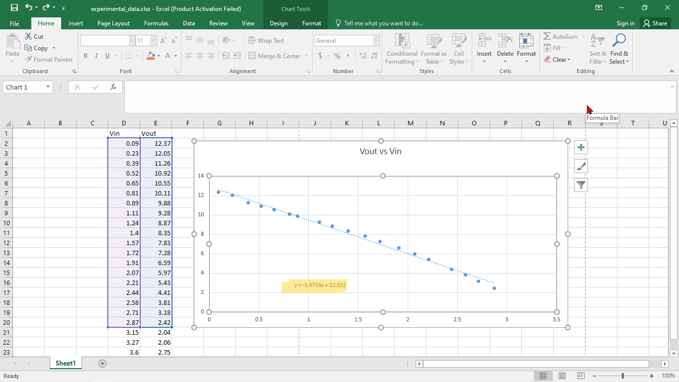
So you have to start by taking values of Vbuf (output voltage of op-amp) and output voltage by changing the voltage using the rotary encoder and then plotting it into an Excel sheet you will get a graph as below.
You may get a linear plot in the middle and non-linear at the edges but don’t worry you can take the linear part and plot the curve, now that you have the relationship between Vin and out you can see the equation of a curve, which now you have to change in terms of set voltage(injection voltage), if you just copy and paste the equation in the code it won’t work!!!
I have had problems with this minor error so I am asking all readers to keep this in mind.
I’m using Excel but you can use any software or even pen and paper, now you can see that the relation between input and output voltage is inversely proportional, and that too that’s linear its very much clear from the plot, and I’ve omitted certain values because after certain value the line saturates and the voltage doesn’t change.
Now you can fit a linear trend line and go to line 312 in the firmware change the equation and upload the code, the voltage control should work as expected.
Source Code
The code for the IoT-enabled Variable Programmable Digital Power Supply with ESP8266 is written in Arduino IDE.
Libraries Used
- ESPAsyncTCP.h and ESPAsyncWebServer.h: To set up a web server.
- LittleFS.h: Filesystem library for handling file storage.
- Arduino_JSON.h: For handling JSON data.
- LiquidCrystal_I2C.h: To control the I2C 16×2 LCD.
- ADS1X15.h: For interfacing ADS1115 with the MCU.
From the following line 120, change the WiFi SSID and Password.
|
1 2 3 |
// Replace with your network credentials const char* ssid = "Note 10s"; const char* password = "abcd1234"; |
Make sure to replace “Your_SSID” and “Your_PASSWORD” with your WiFi network name and password.
Here is the complete code for the project.
|
1 2 3 4 5 6 7 8 9 10 11 12 13 14 15 16 17 18 19 20 21 22 23 24 25 26 27 28 29 30 31 32 33 34 35 36 37 38 39 40 41 42 43 44 45 46 47 48 49 50 51 52 53 54 55 56 57 58 59 60 61 62 63 64 65 66 67 68 69 70 71 72 73 74 75 76 77 78 79 80 81 82 83 84 85 86 87 88 89 90 91 92 93 94 95 96 97 98 99 100 101 102 103 104 105 106 107 108 109 110 111 112 113 114 115 116 117 118 119 120 121 122 123 124 125 126 127 128 129 130 131 132 133 134 135 136 137 138 139 140 141 142 143 144 145 146 147 148 149 150 151 152 153 154 155 156 157 158 159 160 161 162 163 164 165 166 167 168 169 170 171 172 173 174 175 176 177 178 179 180 181 182 183 184 185 186 187 188 189 190 191 192 193 194 195 196 197 198 199 200 201 202 203 204 205 206 207 208 209 210 211 212 213 214 215 216 217 218 219 220 221 222 223 224 225 226 227 228 229 230 231 232 233 234 235 236 237 238 239 240 241 242 243 244 245 246 247 248 249 250 251 252 253 254 255 256 257 258 259 260 261 262 263 264 265 266 267 268 269 270 271 272 273 274 275 276 277 278 279 280 281 282 283 284 285 286 287 288 289 290 291 292 293 294 295 296 297 298 299 300 301 302 303 304 305 306 307 308 309 310 311 312 313 314 315 316 317 318 319 320 321 322 323 324 325 326 327 328 329 330 331 332 333 334 335 336 337 338 339 340 341 342 343 344 345 346 347 348 349 350 351 352 353 354 355 356 357 358 359 360 361 362 363 364 365 366 367 368 369 370 371 372 373 374 375 376 377 378 379 380 381 382 383 384 385 |
// // FILE: Esp8266_digital_powersupply.ino // AUTHOR: Rabindra Sharma // PURPOSE: To make a voltage control // URL: https://diyprojectlab.com // // Pin definitions and addresses: // I2C address of ADC: 0x48 // I2C address of LCD: 0x27 // SDA pin: GPIO 4 // SCL pin: GPIO 5 // // Rotary encoder pins: // CLK: GPIO 13 // DT: GPIO 12 // SW: GPIO 14 // PWM: GPIO 15 (connected to RC filter) // #define CLK_PIN 13 // The ESP8266 pin D7 connected to the rotary encoder's CLK pin #define DT_PIN 12 // The ESP8266 pin D6 connected to the rotary encoder's DT pin #define SW_PIN 14 // The ESP8266 pin D5 connected to the rotary encoder's SW pin #define PWM_PIN 15 // The ESP8266 pin D8 IS CONNECTED TO RC FILTER #define DIRECTION_CW 0 // clockwise direction #define DIRECTION_CCW 1 // counter-clockwise direction // Libraries #include <Arduino.h> #include <ESP8266WiFi.h> #include <ESPAsyncTCP.h> #include <ESPAsyncWebServer.h> #include "LittleFS.h" #include <Arduino_JSON.h> #include <LiquidCrystal_I2C.h> #include "ADS1X15.h" #include <SPI.h> #include <Wire.h> //variables volatile float vset = 0 ; volatile int pwmval = 1023 ; float min_set = 1 ; float max_set = 12 ; float prevtime = 0 ; float prevtime1 = 0 ; float current_zero_error = -1 ; float input_current = 0 ; float input_voltage = 0 ; float vcc = 0 ; volatile float voltage_set = 0.0 ; bool debug = 1 ; volatile bool runmode = 0; //volatile float counter = 0; volatile int direction = DIRECTION_CW; volatile unsigned long itrlast_time; // for debouncing volatile unsigned long itrlast_time1; // for debouncing switch //volatile int prev_counter; volatile int CLK_state; volatile int prev_CLK_state; LiquidCrystal_I2C lcd(0x27, 16, 2); // I2C address 0x27, 16 column and 2 rows ADS1115 ADS(0x48); IRAM_ATTR void INTERRUPT_handler() { if (( (millis() - itrlast_time) < 50 )) {// debounce time is 50ms return; } if (runmode == 0 ) { return; } if ((digitalRead(DT_PIN) == HIGH )) { // The encoder is rotating in counter-clockwise direction => decrease the counter voltage_set -= 0.1; direction = DIRECTION_CCW; //print("Ccw rotation counter:" + String(counter)); } else { // The encoder is rotating in clockwise direction => increase the counter voltage_set += 0.1 ; direction = DIRECTION_CW; //Serial.print("Cw rotation voltage_set:" + String(voltage_set)); } voltage_set = constrain(voltage_set,2,12); itrlast_time = millis(); } IRAM_ATTR void interrupt2() { if ((millis() - itrlast_time1) < 80) { // debounce time is 80ms return; } if (digitalRead(SW_PIN) == LOW) { //dosomething if (runmode == 0 ) { runmode = 1; Serial.print("change to 1 "); } else if (runmode == 1 ) { runmode = 0; Serial.print("change to 0 "); } } itrlast_time1 = millis(); } // Replace with your network credentials const char* ssid = "Note 10s"; const char* password = "abcd1234"; // Create AsyncWebServer object on port 80 AsyncWebServer server(80); // Create a WebSocket object AsyncWebSocket ws("/ws"); // Json Variable to Hold Sensor Readings JSONVar readings; // Timer variables unsigned long lastTime = 0; unsigned long lastTime1 = 0; unsigned long timerDelay = 1000; unsigned long timerDelay1 = 5000; // Get Sensor Readings and return JSON object String getSensorReadings() { readings["voltage_s"] = String(voltage_set); readings["voltage"] = String(input_voltage); readings["current"] = String(input_current); String jsonString = JSON.stringify(readings); return jsonString; } // Initialize LittleFS void initFS() { if (!LittleFS.begin()) { Serial.println("An error has occurred while mounting LittleFS"); } else { Serial.println("LittleFS mounted successfully"); } } // Initialize WiFi void initWiFi() { WiFi.mode(WIFI_STA); WiFi.begin(ssid, password); Serial.print("Connecting to WiFi .."); while (WiFi.status() != WL_CONNECTED) { Serial.println('.'); delay(1000); } Serial.println(WiFi.localIP()); } void notifyClients(String sensorReadings) { ws.textAll(sensorReadings); } void handleWebSocketMessage(void *arg, uint8_t *data, size_t len) { AwsFrameInfo *info = (AwsFrameInfo*)arg; if (info->final && info->index == 0 && info->len == len && info->opcode == WS_TEXT) { String message = (char*)data; JSONVar doc = JSON.parse(message); if (JSON.typeof(doc) == "undefined") { Serial.println("Parsing input failed!"); return; } /* if (doc.hasOwnProperty("voltage_s")) { Serial.print("myObject[\"voltage_s\"] = "); Serial.println( doc["voltage_s"]); } */ String datrec = doc["voltage_s"]; voltage_set = datrec.toDouble(); if (debug == 1) { Serial.print("Data received voltage set :" + String(doc["voltage_s"])); } } } void onEvent(AsyncWebSocket * server, AsyncWebSocketClient * client, AwsEventType type, void *arg, uint8_t *data, size_t len) { switch (type) { case WS_EVT_CONNECT: Serial.printf("WebSocket client #%u connected from %s\n", client->id(), client->remoteIP().toString().c_str()); break; case WS_EVT_DISCONNECT: Serial.printf("WebSocket client #%u disconnected\n", client->id()); break; case WS_EVT_DATA: handleWebSocketMessage(arg, data, len); break; case WS_EVT_PONG: case WS_EVT_ERROR: break; } } void initWebSocket() { ws.onEvent(onEvent); server.addHandler(&ws); } void setup() { Serial.begin(115200); initWiFi(); initFS(); initWebSocket(); // Web Server Root URL server.on("/", HTTP_GET, [](AsyncWebServerRequest * request) { request->send(LittleFS, "/index.html", "text/html"); }); server.serveStatic("/", LittleFS, "/"); // Start server server.begin(); pinMode(PWM_PIN, OUTPUT); analogWriteRange(1023); analogWrite(PWM_PIN, 1023); pinMode(CLK_PIN, INPUT); pinMode(DT_PIN, INPUT); pinMode(SW_PIN, INPUT_PULLUP); adc_init(); init_display(); attachInterrupt(digitalPinToInterrupt(SW_PIN), interrupt2, FALLING); attachInterrupt(digitalPinToInterrupt(CLK_PIN), INTERRUPT_handler, RISING); delay(200); prev_CLK_state = digitalRead(CLK_PIN); itrlast_time = millis() ; itrlast_time1 = millis() ; } void loop() { if ((millis() - lastTime1) > timerDelay1) { measure(); voltage_drive(); String sensorReadings = getSensorReadings(); if (debug == 1 ) { Serial.println(sensorReadings); } notifyClients(sensorReadings); lastTime1 = millis(); } if ((millis() - lastTime) > timerDelay) { if (runmode == 0 ) { lcd.clear(); lcd.setCursor(0, 0); lcd.print(String(voltage_set) + String(" ") + String(input_voltage) ) ; lcd.setCursor(0, 1); lcd.print(String("Current : ") + String(input_current) + String("A") ) ; } if (runmode == 1) { lcd.clear(); lcd.setCursor(0, 0); lcd.print(String("Set Voltage :") ) ; lcd.setCursor(0, 1); lcd.print(String(voltage_set) + String("V")) ; } if (debug == 1 ) { Serial.print("progmode :" + String(runmode)); } lastTime = millis(); } ws.cleanupClients(); } void voltage_drive() { //vset = 2.76456 - 0.2667 * voltage_set; //vset = constrain(vset , 0 , 3.6); vset = (37253-2881*voltage_set)/10000; pwmval = (int)((vset * 1023) / 3.6); analogWrite(PWM_PIN,pwmval); if (debug) { Serial.println("The set voltage " + String(vset)); Serial.println("The pwm is " + String(pwmval)); } } void init_display() { lcd.init(); // initialize the lcd lcd.backlight(); lcd.clear(); lcd.setCursor(0, 0); lcd.println("Esp PowerSupply"); } void adc_init() { Wire.begin(); ADS.begin(); ADS.setGain(0); // 6.144 volt } void measure() { int16_t raw_data1 = 0; int16_t raw_data2 = 0; int16_t raw_data3 = 0; raw_data1 = ADS.readADC(1); raw_data2 = ADS.readADC(2); raw_data3 = ADS.readADC(3); float vref = (ADS.toVoltage(raw_data3) * 3.165 ) / 2; float AcsValue = 0.0, Samples = 0.0, AvgAcs = 0.0, AcsValueF = 0.0; for (int x = 0; x < 11; x++) { //Get 11 samples AcsValue = ADS.readADC(0); //Read current sensor values Samples = Samples + AcsValue; //Add samples together delay (3); // let ADC settle before next sample 3ms } AvgAcs = Samples / 10.0; //Taking Average of Samples //((AvgAcs * (5.0 / 1024.0)) is converitng the read voltage in 0-5 volts //2.5 is offset(I assumed that arduino is working on 5v so the viout at no current comes //out to be 2.5 which is out offset. If your arduino is working on different voltage than //you must change the offset according to the input voltage) //0.066(66mV) is rise in output voltage when 1A current flows at input AcsValueF = (vref - (ADS.toVoltage(AvgAcs) ) ) / 0.066 - current_zero_error ; input_current = -1*AcsValueF ; input_voltage = ADS.toVoltage(raw_data2) * 3.165 ; vcc = ADS.toVoltage(raw_data3) * 3.165 ; if (debug == 1) { Serial.println("------------------------------"); Serial.println((input_current), 3); Serial.println("Current drawn (A)"); Serial.println(input_voltage, 3); Serial.println("Input voltage "); Serial.println(vcc, 3); Serial.println("Supply voltage"); Serial.println("------------------------------"); } } |
Voltage Control Logic
- voltage_drive Function: This function calculates the voltage set point based on a linear equation, edits the PWM output, sets a linear trend line, and then goes to line 312 in the firmware (code). Edit the equation and upload the code. Now the voltage control should work correctly.
|
1 2 3 4 5 6 7 8 9 |
void voltage_drive() { vset = (37253 - 2881 * voltage_set) / 10000; pwmval = (int)((vset * 1023) / 3.6); analogWrite(PWM_PIN, pwmval); if (debug) { Serial.println("The set voltage " + String(vset)); Serial.println("The pwm is " + String(pwmval)); } } |
Now copy the above code and upload it to the ESP8266 Board.
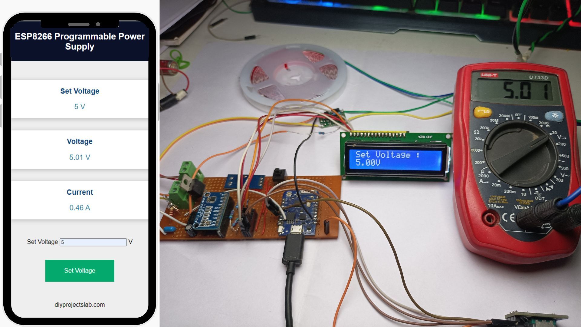
Working IoT Programmable Power Supply with ESP8266 WebServer
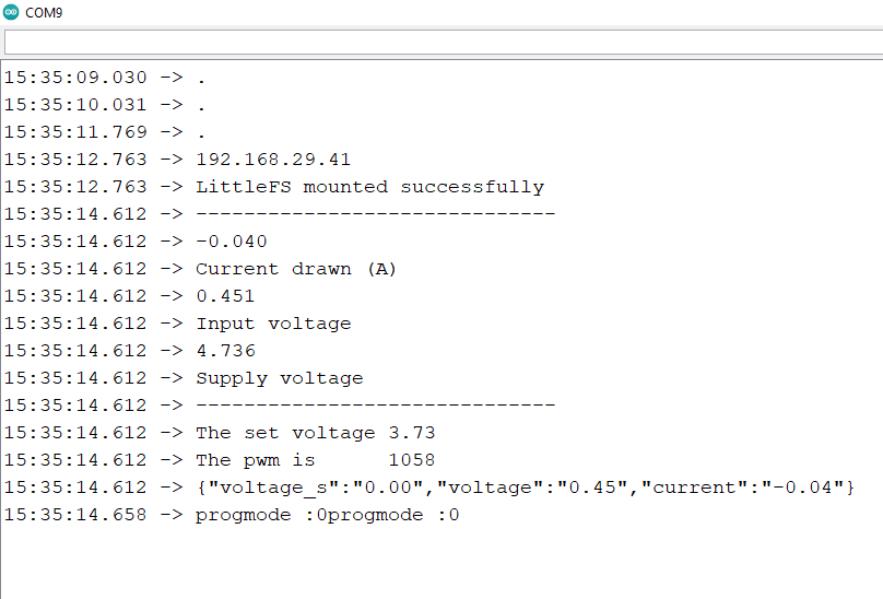
After uploading the code to the ESP8266, the ESP8266 will connect to the WiFi network and start a web server. To observe the IP address, open the Serial Monitor.
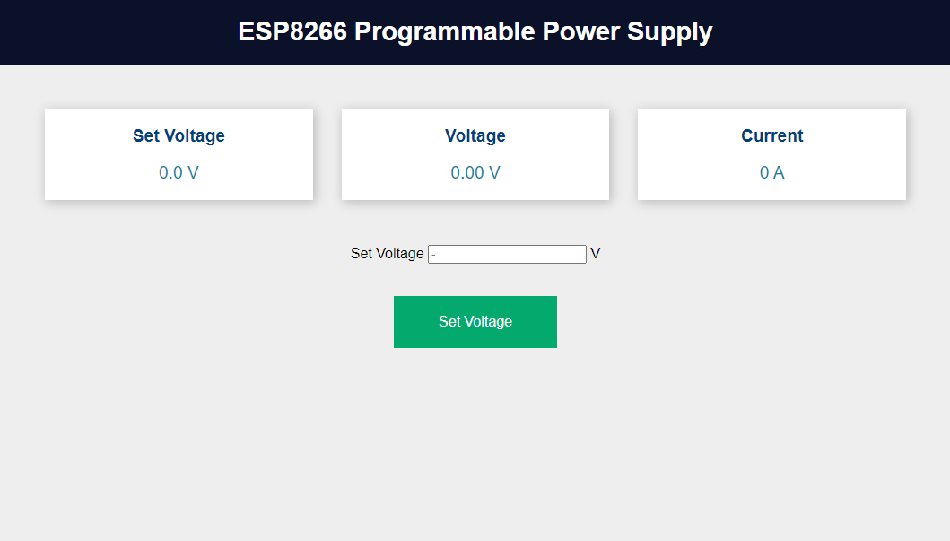
Copy the IP address from the Arduino Serial Monitor and paste it into a web browser which connected to the same network. Once you press enter, a beautiful webpage will be displayed on your screen.
Now everything is set up. You can enter your desired voltage in the “Set Voltage” box on the webpage and click on “Set Voltage“.
The system will then provide your chosen output voltage.
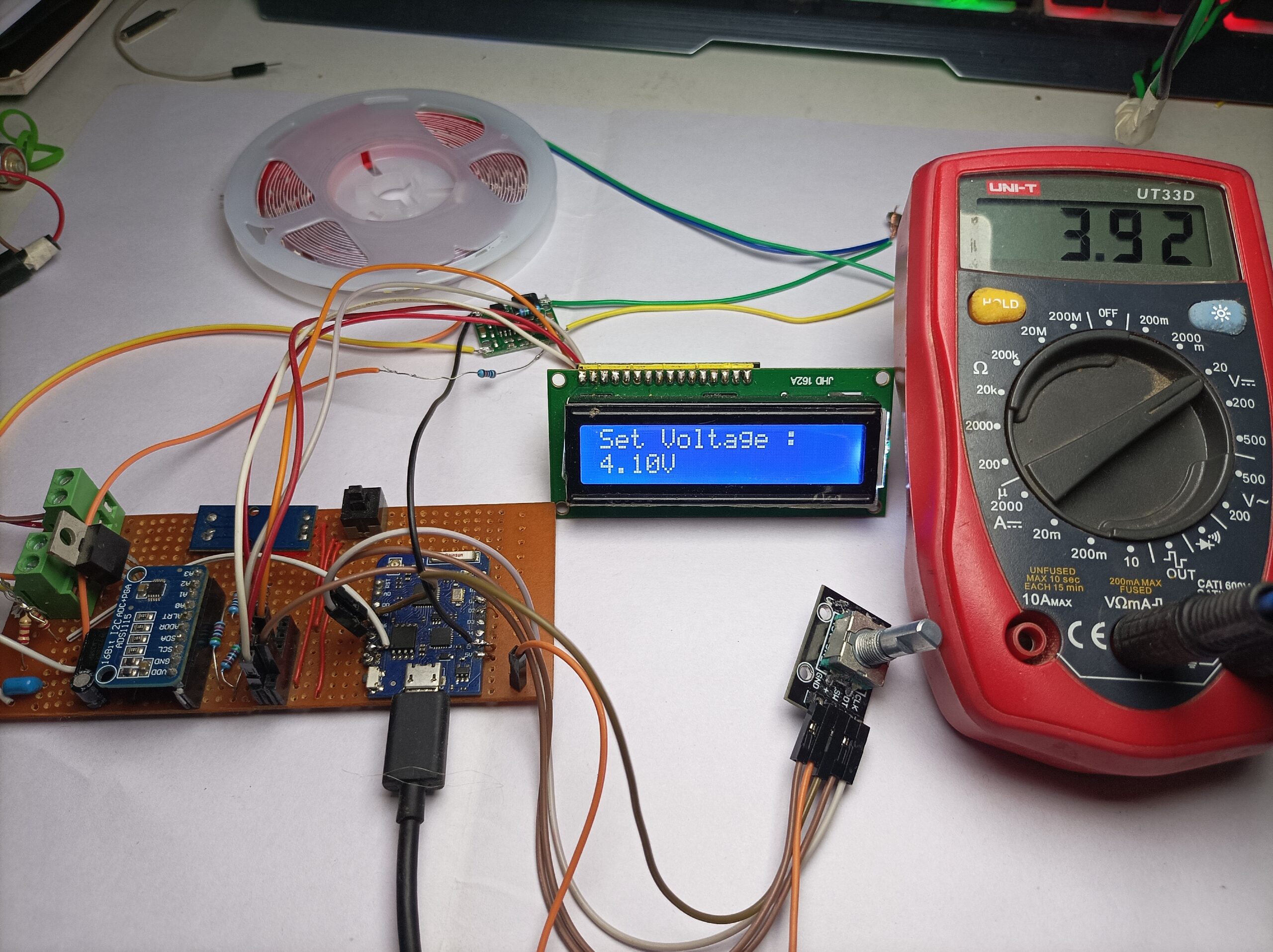
You can also control the voltage manually using the rotary encoder. Rotate the encoder to change the voltage and then click the encoder to set the voltage. The current voltage will be displayed on the 16×2 display.

