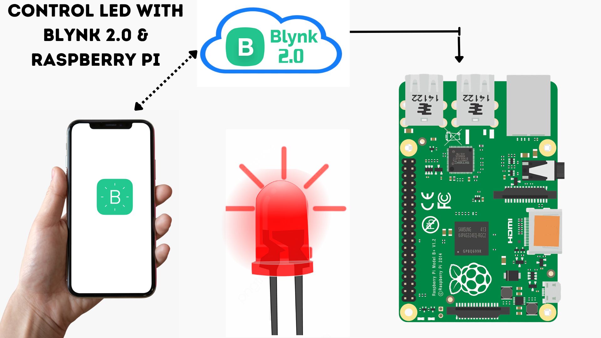
In this tutorial, we will show you how to control an LED wirelessly using the Blynk 2.0 App & Raspberry Pi using the Python Code.
Blynk allows us to create custom smartphone interfaces to interact with hardware remotely. With Raspberry Pi’s built-in Wi-Fi, we’ll connect it to the Blynk app and control the LED. By the end, you’ll have a project that lets you turn the LED on and off from anywhere using your smartphone. Checkout our previous post on How to Use Blynk 2.0 With Raspberry Pi Pico W Using Micropython
Required Material
To get started, you will need a few components:
- Raspberry Pi Board
- 220-ohm resistor
- LED
- Breadboard
- Jumper wires
- Blynk app
Wiring Diagram
To set up the hardware for controlling LED with the Blynk and Raspberry Pi, connect the LED to the RPI board. Follow the below image to complete the hardware setup and circuit:
- Attach the LED’s positive leg to GPIO0 (Pin 1).
- It’s negative leg to any GND pin on the Raspberry Pi board.
- Add a 220-ohm resistor between the LED’s negative leg and the GND pin
Now that the hardware is ready, you can move on to configuring the Blynk app and programming the Raspberry Pi board. checkout How to Control WS2812 LED w/ Raspberry Pi Pico W & Adafruit IO
Configuring the Blynk 2.0 App
To control the LED using Blynk and Raspberry Pi, first, create a Blynk account on blynk.cloud or sign in with your registered email ID.
After signing in, it’s time to create a template. Click on ‘+New Template‘ to start.
In the modal window that appears, provide basic template information and click ‘Done’
Name the template “Raspberry Pi”, and select “Hardware Type” as “Raspberry Pi” and “Connection Type” as “WiFi
Templates are sets of elements and configurations used to display all devices of a particular type. They are created and edited in developer mode.
The template is now created.
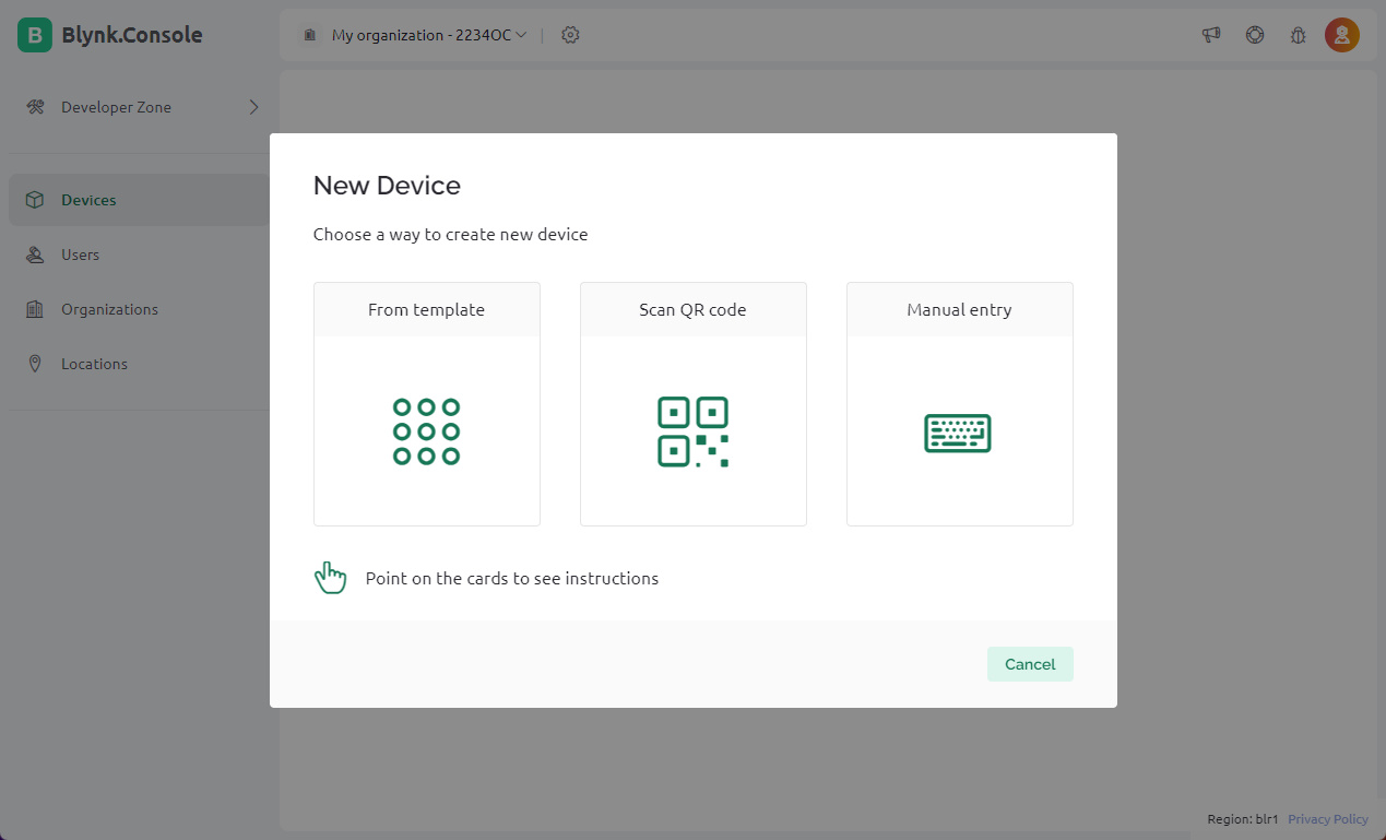
Now that the template is created, it’s time to add devices.
Choose “New Device” from the template

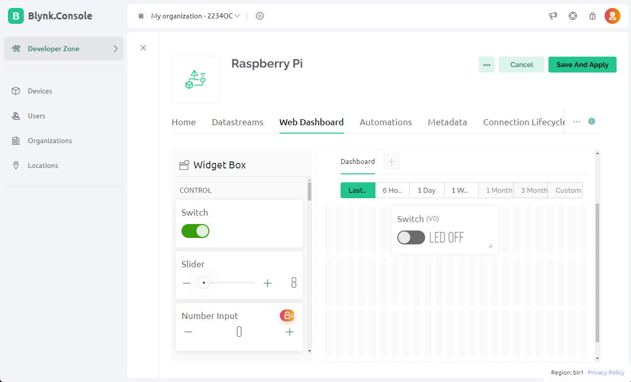
Now, navigate to the dashboard and choose ‘Web Dashboard’.
Drag a switch from the widget box and place it on the dashboard screen.
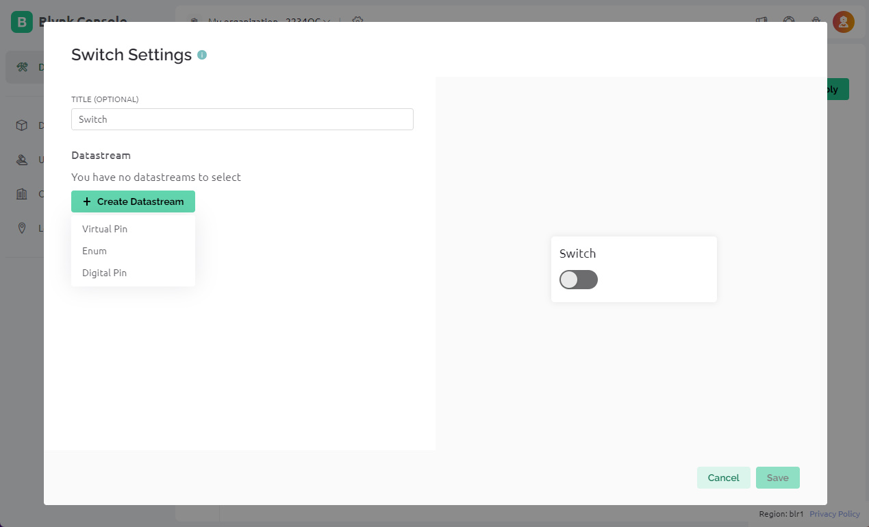
Click on the switch, then select “Settings”. Here, set up the switch by giving it a title and creating a datastream as a virtual pin.
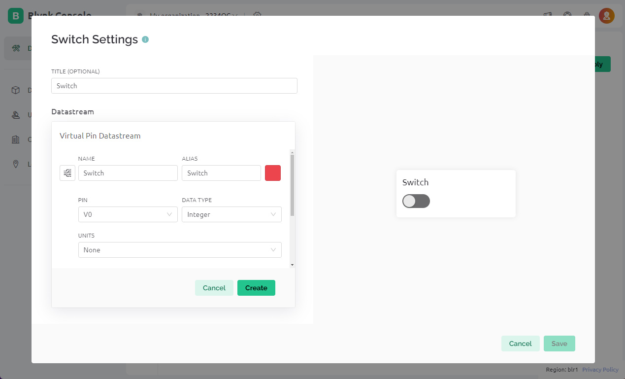

Additionally, to control the LED with a mobile app or mobile dashboard, set up the mobile phone dashboard using a similar process as explained above.
How to install Blynk 2.0 Library on Raspberry Pi
To control an LED using the Blynk 2.0 App and Raspberry Pi, you need to install the Blynk library. Use the following command to install the library
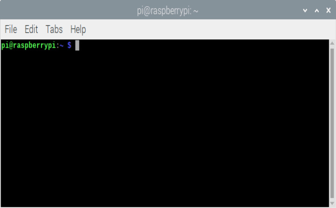
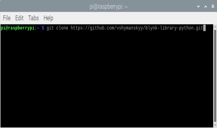
Open the Terminal Window on the Raspberry Pi desktop.
Once opened, execute the following command to install the New Blynk library:
|
1 |
git clone https://github.com/vshymanskyy/blynk-library-python.git |
This command will install a copy of the Blynk Python Library folder into the root folder of your Raspberry Pi.
You can now compile any Blynk programming code within this blynk-library-python folder.
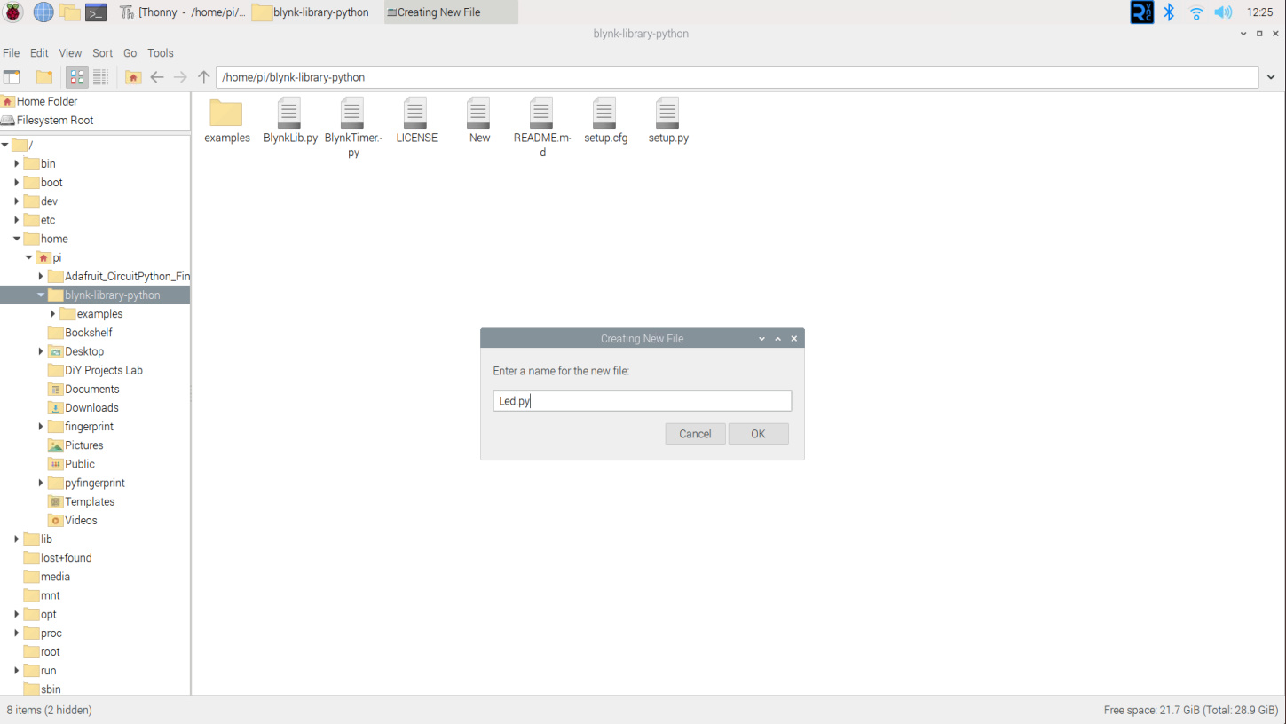
To do so, create a new led.py file directly inside the “blynk-library-python” folder.
Then, copy the following Python code into the file and save it. You can run this file using Thonny IDE or any Python IDE
Source Code
You need to change the Blynk Authentication Token on the following lines.
|
1 2 3 4 5 6 7 8 9 10 11 12 13 14 15 16 17 18 19 20 21 22 23 24 25 26 27 28 29 30 31 32 |
import BlynkLib import RPi.GPIO as GPIO # Define GPIO pin for the device device_pin = 14 # Setup GPIO pin GPIO.setmode(GPIO.BCM) GPIO.setup(device_pin, GPIO.OUT) GPIO.output(device_pin, GPIO.LOW) # Initialize Blynk blynk = BlynkLib.Blynk('vWMZvMkt5OC8gI-6aCMHgX8VuaMjeKWR') # Device control through V0 virtual pin @blynk.on("V0") def v0_write_handler(value): if int(value[0]) is not 0: GPIO.output(device_pin, GPIO.HIGH) print('Device HIGH') else: GPIO.output(device_pin, GPIO.LOW) print('Device LOW') # Function to sync the data from virtual pins @blynk.on("connected") def blynk_connected(): print("Alert: Hi! Raspberry Pi Connected to New Blynk2.0") # Run Blynk while True: blynk.run() |
Controlling LEDs with Blynk 2.0 & Raspberry Pi
To run the code on the Raspberry Pi board, save the code into a Python file, for example, led_control.pyon your Raspberry Pi. Then, execute the Python file using the following command in the terminal
|
1 2 |
cd blynk-library-python sudo python led.py |
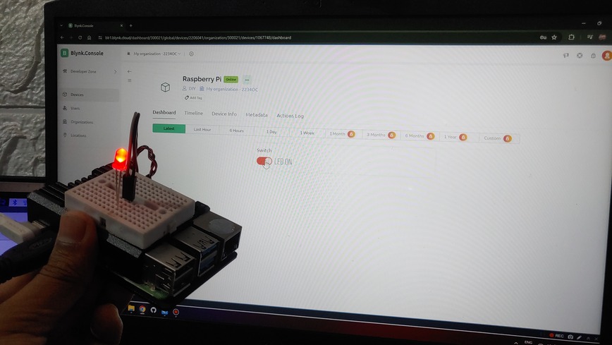
You can now test the LED control using the Blynk web app. Simply open the web app, go to the project dashboard, and click on the button widget. This action should turn on the LED
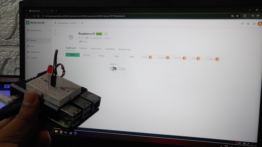
Click the button widget again, and the LED should turn off.
Here is a demonstration GIF video
If you’ve understood the process of building this system, great! If you face any issues, just leave a comment, and I’ll assist you

