In this tutorial, we’ll be using the MAX30102 pulse oximeter sensor with Arduino to measure heart rate, blood oxygen saturation levels, and Temperature. The MAX30102 is a sensor that can measure heart rate and blood oxygen levels. We’ll also be using the SparkFun MAX3010x library. we will be using an OLED Display to view the value of SpO2 and BPM.
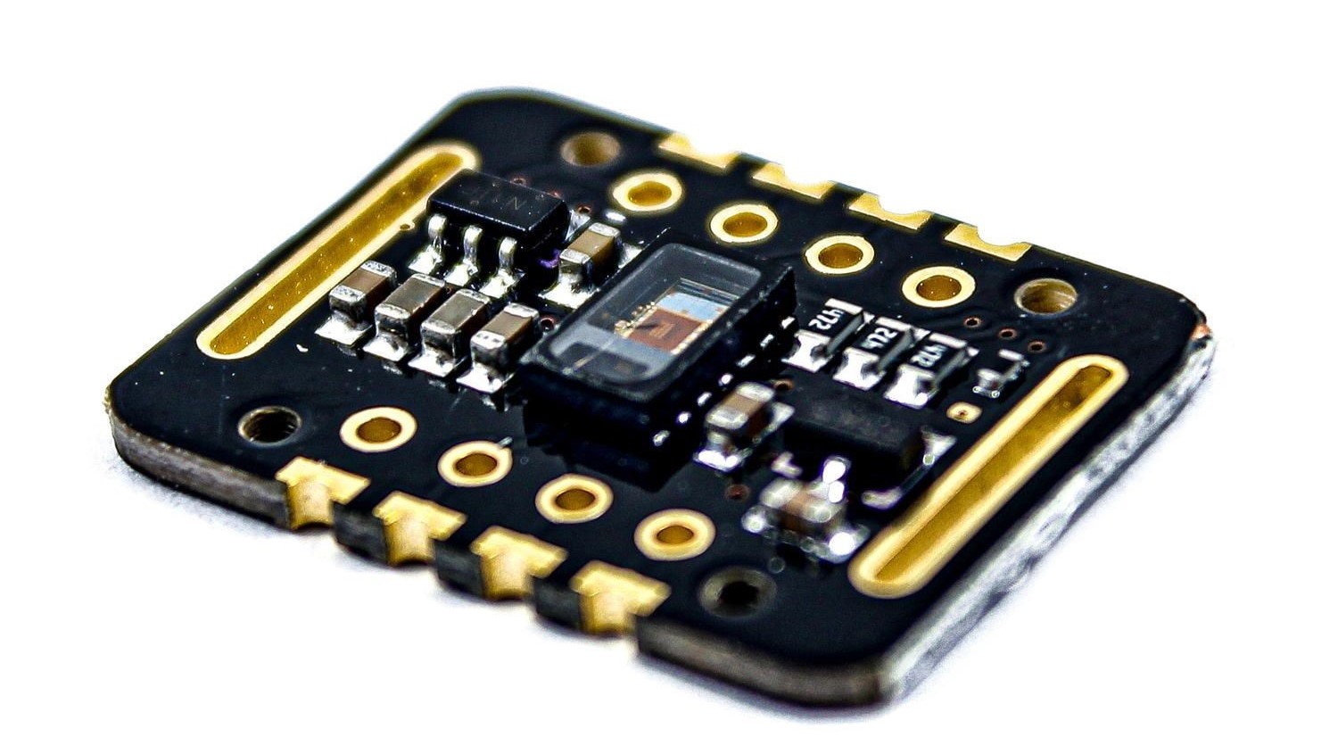
The MAX30102 is a Pulse Oximetry and heart rate monitor sensor solution. It combines two LEDs, a photodetector, optimized optics, and low-noise analog signal processing to detect pulse oximetry and heart-rate signals. You can use this sensor with any microcontroller like Arduino, Raspberry Pi, ESP8266, or ESP32 and easily measure the patient’s health parameters.
Checkout our previous posts
- IoT Patient Health Monitoring System Project Using ESP32 | Real-time
- Heart Beat Display using Pulse Sensor with Arduino & OLED
- Monitor Pulse Rate (BPM) With Arduino & Pulse Sensor
Thanks to the support and sponsorship from NextPCB, Guys if you have a PCB project, I would like to recommend NextPCB for all your PCBs. Be sure to see their website for exciting discounts, coupons, and more
NextPCB offers high-quality, reliable PCB starting at $1.9, and multilayer starting at $6.9. Also, everyone can enjoy free PCB assembly for 5 boards!
Required Material
- MAX30102 Pulse Oximeter Sensor
- Arduino Uno
- OLED Display
- Jumper wires
- Breadboard
MAX30100 Pulse Oximeter Sensor Module
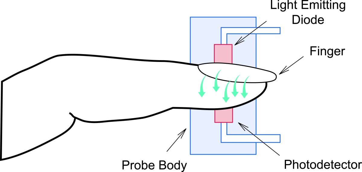
The MAX30102 is a small sensor that you can use to measure your heart rate and the amount of oxygen in your blood. It works by radiating light through your skin (usually on your fingertip) and then measuring how much of that light bounces back. This reflecting light gives the sensor data about your heart rate and oxygen levels, which can be important for monitoring your health.
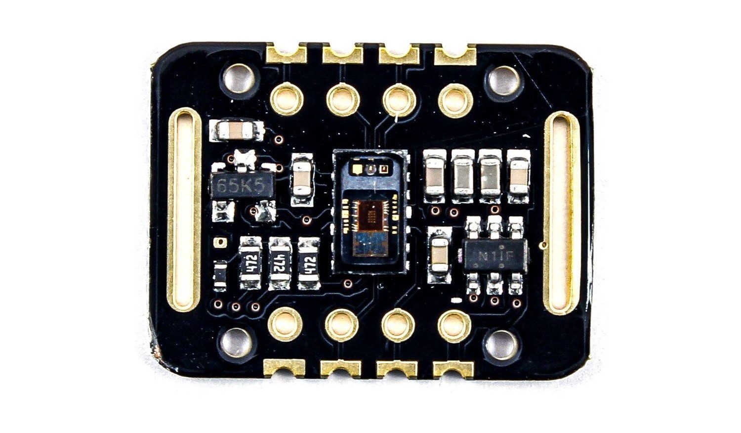
The MAX30102 works by glowing red and infrared light into the skin, usually a fingertip or earlobe. It then measures the amount of reflected rays using a photodetector.
This method called a Photoplethysmogram (PPG), detects differences in blood flow with each heartbeat, allowing it to calculate oxygen saturation (SpO2) and heart rate. Download the MAX30102 datasheet
Specification
Sensor Type:
- Type: Reflective Pulse Oximeter and Heart-Rate Sensor
Light Sources:
- Dual High-Intensity LEDs
- Red LED: Wavelength of around 660nm
- Infrared LED: Wavelength of around 880nm
Detection Method:
- Photodetector to measure the reflected light
Operating Principle:
- Optical Reflection Signal (PPG)
Key Measurements:
- Blood Oxygen Saturation (SpO2) levels
- Heart Rate (Pulse Rate)
Operating Conditions:
- Power Supply Voltage: 3.3V – 5V
- Operating Temperature: -40°C to +85°C
Communication Interface:
- I2C (Inter-Integrated Circuit) Communication Protocol
Additional Features:
- Low Power Consumption
- Integrated Ambient Light Cancellation
- High Sample Rate Ability
Applications:
- Health Devices
- Medical Monitors
- Smartwatches
- Sports and Exercise Gadgets
- Remote Health Monitoring
- IoT Devices
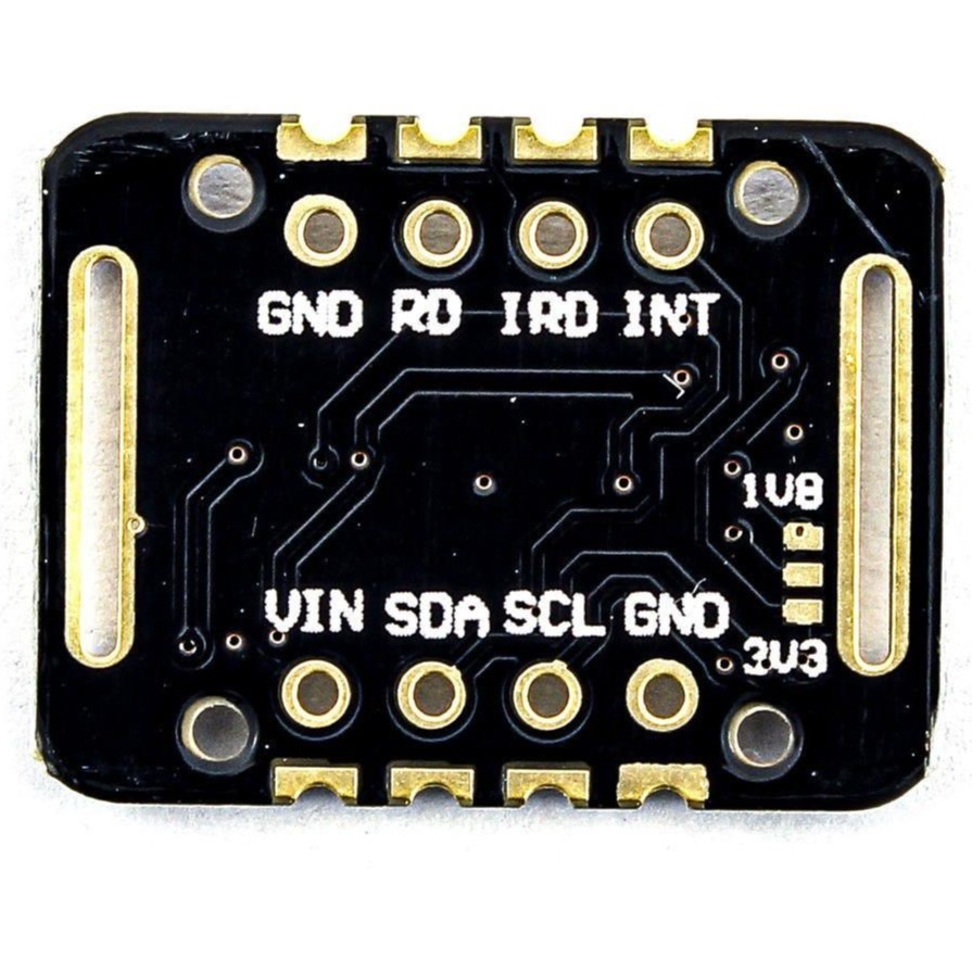
Pinout MAX30102 PPG Heart Rate and Pulse Oximeter Sensor
- GND: Grounding
- RD: RD LED Grounding Terminal (doesn’t need to be connected)
- IRD: IR LED Grounding Terminal (doesn’t need to be connected)
- INT: Interrupt PIN
- VIN: 3.3V To 5V
- SDA: I2C Bus Data
- SCL: I2C Bus Clock
- GND: Grounding
Note – 3-Bit Pad: I2C Bus Pull-Up Level (Selectable between 1.8V and 3.3V based on Pin Master Voltage)
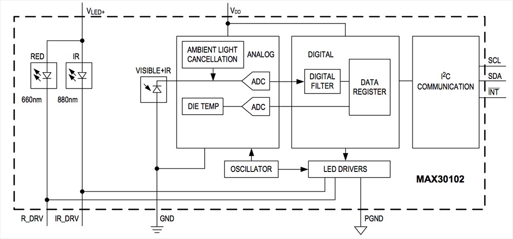
Block Diagram
How Does a Pulse Oximeter Work?
A pulse oximeter works by shining light (usually red and infrared) through your skin, generally at your fingertip. The amount of light absorbed indicates the level of oxygen saturation in your blood. During a pulse oximetry reading, a little clamp-like instrument is put on a finger, earlobe, or toe, etc.
Here’s how it works in simple terms:
- The light shines through your finger.
- Blood absorbs some of the light.
- Then it calculates your oxygen level (SpO2) and heart rate based on light absorption.
Heart Rate Measurement
The oxygenated hemoglobin (HbO2) in the arterial blood has the factor of absorbing IR light. The redder the blood (the higher the hemoglobin), the more IR light is absorbed.
As the blood is pumped through the finger with each heartbeat, the amount of reflected light changes, creating a changing waveform at the output of the photodetector.
MAX3010x Sparkfun Arduino Library
The library for MAX3010x is developed by Adafruit as well as Sparkfun. However, we will use the SGP30 Sparkfun Arduino Library in this project.
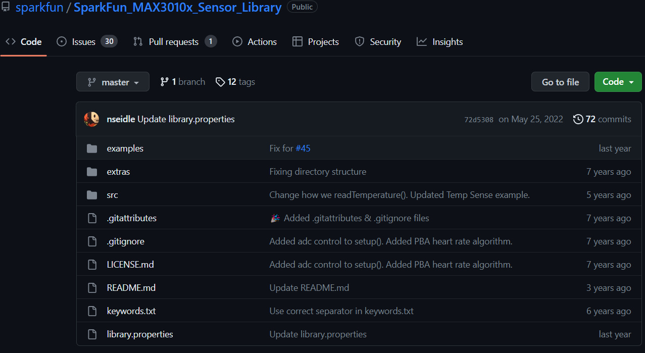
You can download the MAX3010x Library from Github. Link. Download the library and add it to your Arduino IDE through the library manager.
Interfacing MAX30102 PPG Heart Rate and Pulse Oximeter Sensor With Arduino
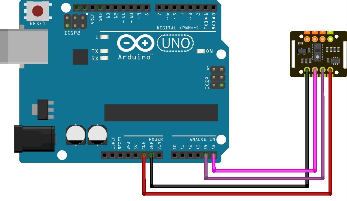
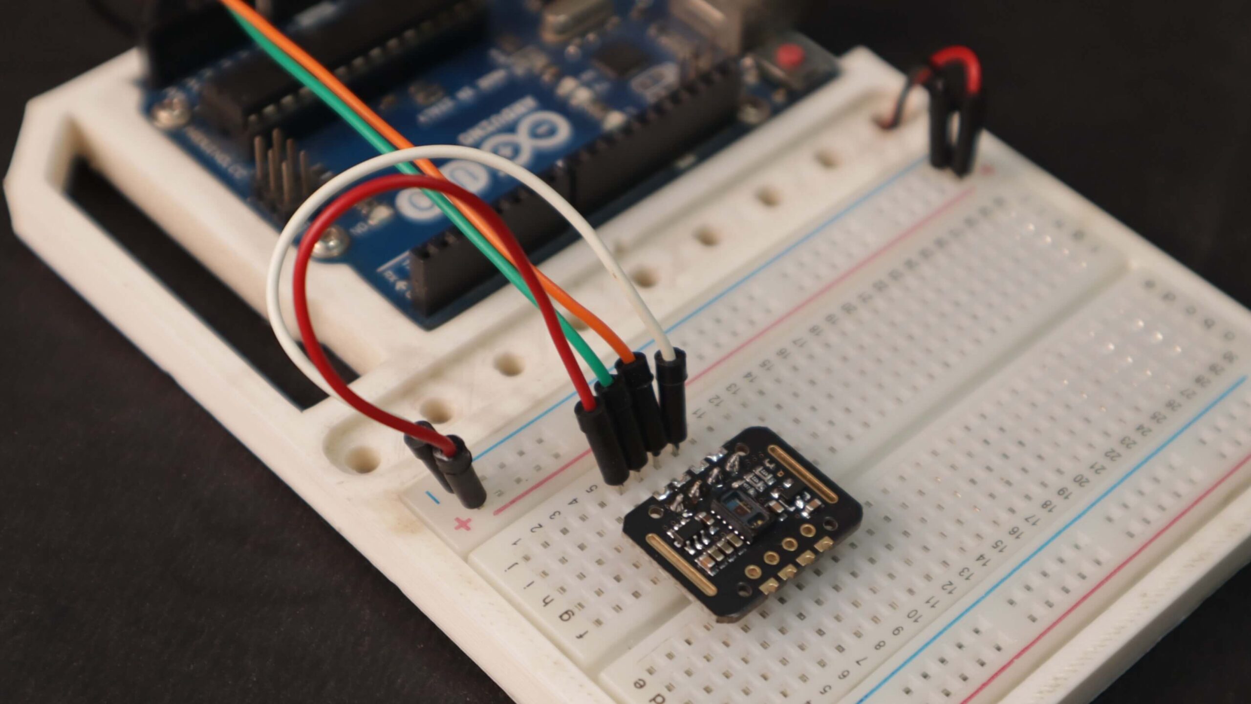
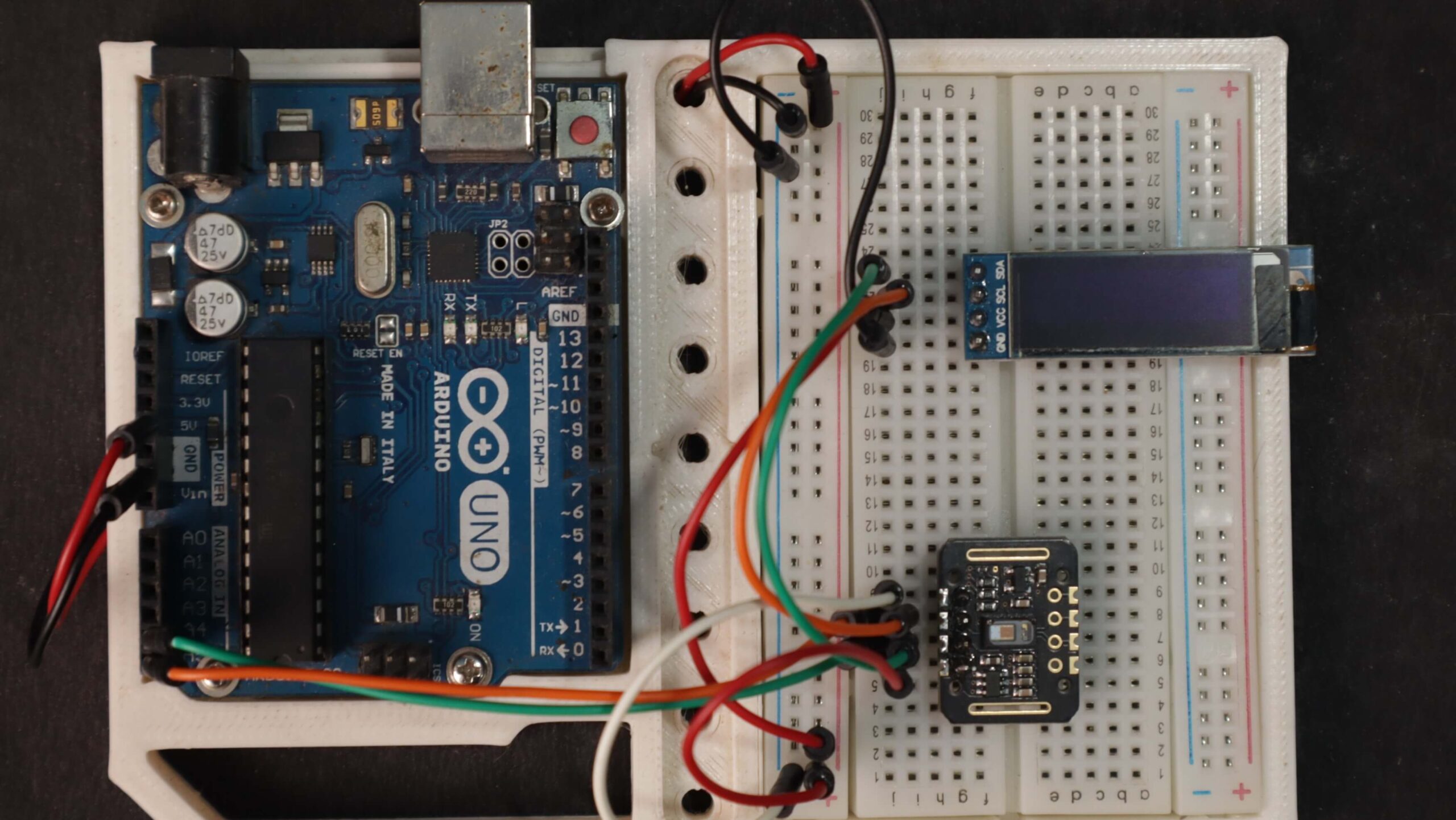
Now let us interface the MAX30102 Sensor with the Arduino Board. The connection diagram between Arduino & MAX30102 is straightforward.
Connect the VCC & GND pin of MAX30102 to Arduino 5V & GND pin respectively. Since MAX30102 is an I2C module, connect its SDA & SCL pins to Arduino A4 & A5 pins respectively.
Source Code / MAX30102 Pulse Oximeter Arduino Code
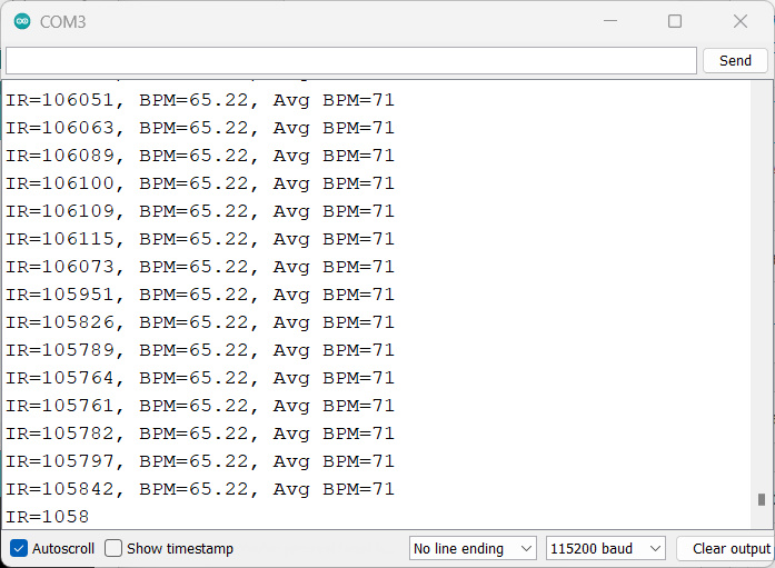
The following code is taken from the example of the Sparkfun library. The code outputs measurements of IR and BPM.
|
1 2 3 4 5 6 7 8 9 10 11 12 13 14 15 16 17 18 19 20 21 22 23 24 25 26 27 28 29 30 31 32 33 34 35 36 37 38 39 40 41 42 43 44 45 46 47 48 49 50 51 52 53 54 55 56 57 58 59 60 61 62 63 64 65 66 67 68 69 70 |
#include <Wire.h> #include "MAX30105.h" #include "heartRate.h" MAX30105 particleSensor; const byte RATE_SIZE = 4; //Increase this for more averaging. 4 is good. byte rates[RATE_SIZE]; //Array of heart rates byte rateSpot = 0; long lastBeat = 0; //Time at which the last beat occurred float beatsPerMinute; int beatAvg; void setup() { Serial.begin(115200); Serial.println("Initializing..."); // Initialize sensor if (!particleSensor.begin(Wire, I2C_SPEED_FAST)) //Use default I2C port, 400kHz speed { Serial.println("MAX30105 was not found. Please check wiring/power. "); while (1); } Serial.println("Place your index finger on the sensor with steady pressure."); particleSensor.setup(); //Configure sensor with default settings particleSensor.setPulseAmplitudeRed(0x0A); //Turn Red LED to low to indicate sensor is running particleSensor.setPulseAmplitudeGreen(0); //Turn off Green LED } void loop() { long irValue = particleSensor.getIR(); if (checkForBeat(irValue) == true) { //We sensed a beat! long delta = millis() - lastBeat; lastBeat = millis(); beatsPerMinute = 60 / (delta / 1000.0); if (beatsPerMinute < 255 && beatsPerMinute > 20) { rates[rateSpot++] = (byte)beatsPerMinute; //Store this reading in the array rateSpot %= RATE_SIZE; //Wrap variable //Take average of readings beatAvg = 0; for (byte x = 0 ; x < RATE_SIZE ; x++) beatAvg += rates[x]; beatAvg /= RATE_SIZE; } } Serial.print("IR="); Serial.print(irValue); Serial.print(", BPM="); Serial.print(beatsPerMinute); Serial.print(", Avg BPM="); Serial.print(beatAvg); if (irValue < 50000) Serial.print(" No finger?"); Serial.println(); } |
From the board manager, select the Arduino board of your choice. Also, select the COM port. Finally, hit the upload button to upload your code to the Arduino Board.
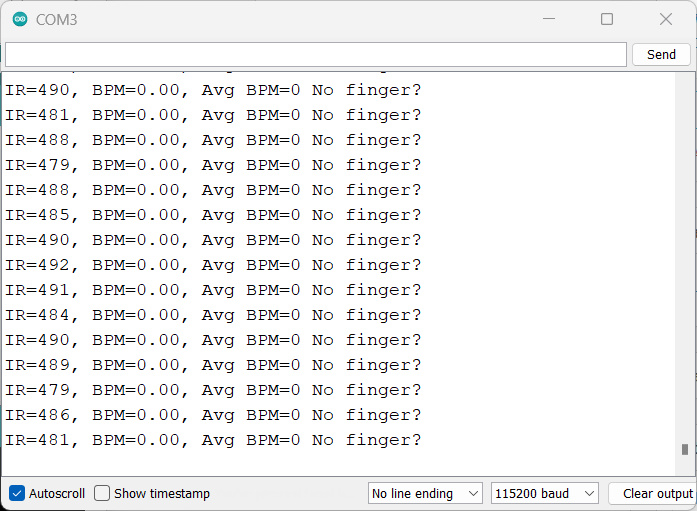
Once code uploading completes, open the serial monitor.
Code For Reading Red & IR
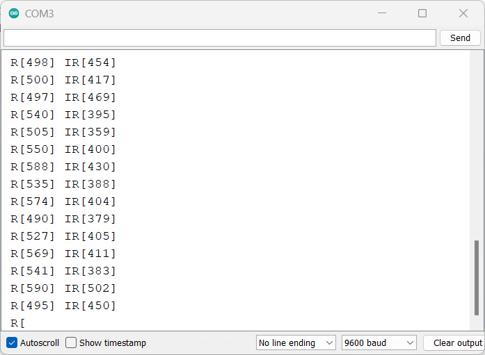
This example code outputs the raw (IR and Red readings) values read by the sensor.
|
1 2 3 4 5 6 7 8 9 10 11 12 13 14 15 16 17 18 19 20 21 22 23 24 25 26 27 28 29 30 31 32 33 34 35 36 37 38 39 40 41 42 43 44 |
#include <Wire.h> #include "MAX30105.h" #include <Adafruit_SSD1306.h> MAX30105 particleSensor; Adafruit_SSD1306 display(-1); // Define an instance of the display void setup() { Serial.begin(9600); // Initialize sensor if (particleSensor.begin() == false) { Serial.println("MAX30102 was not found. Please check wiring/power."); while (1); } particleSensor.setup(); // Configure sensor. Use 6.4mA for LED drive // Initialize the OLED display display.begin(SSD1306_SWITCHCAPVCC, 0x3C); // Address 0x3C for 128x32 display.display(); // Show initial display buffer contents on the screen delay(2000); // Pause for 2 seconds display.clearDisplay(); // Clear the display } void loop() { Serial.print(" R["); Serial.print(particleSensor.getRed()); Serial.print("] IR["); Serial.print(particleSensor.getIR()); Serial.println("]"); // Display sensor readings on the OLED display display.clearDisplay(); display.setTextSize(1); display.setTextColor(SSD1306_WHITE); display.setCursor(0, 0); display.print("Red: "); display.print(particleSensor.getRed()); display.setCursor(0, 10); display.print("IR: "); display.print(particleSensor.getIR()); display.display(); } |
upload it onto your Arduino and open the Serial Terminal to check what the printed values are.
Code for Measure Temperature
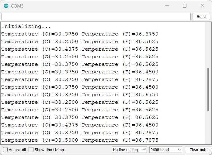
The next example code is for temperature readings from the built-in sensor in both Celsius and Fahrenheit.
|
1 2 3 4 5 6 7 8 9 10 11 12 13 14 15 16 17 18 19 20 21 22 23 24 25 26 27 28 29 30 31 32 33 34 35 36 37 38 39 40 41 42 43 44 45 46 47 48 49 50 51 52 53 54 55 56 57 58 59 |
#include <Wire.h> #include "MAX30105.h" #include <Adafruit_SSD1306.h> MAX30105 particleSensor; Adafruit_SSD1306 display(-1); // Define an instance of the display void setup() { Serial.begin(9600); Serial.println("Initializing..."); // Initialize sensor if (!particleSensor.begin(Wire, I2C_SPEED_FAST)) // Use default I2C port, 400kHz speed { Serial.println("MAX30102 was not found. Please check wiring/power."); while (1); } // The LEDs are very low power and won't affect the temp reading much but // you may want to turn off the LEDs to avoid any local heating particleSensor.setup(0); // Configure sensor. Turn off LEDs particleSensor.enableDIETEMPRDY(); // Enable the temp ready interrupt. This is required. // Initialize the OLED display display.begin(SSD1306_SWITCHCAPVCC, 0x3C); // Address 0x3C for 128x32 display.display(); // Show initial display buffer contents on the screen delay(2000); // Pause for 2 seconds display.clearDisplay(); // Clear the display } void loop() { float temperatureC = particleSensor.readTemperature(); Serial.print("Temperature (C)="); Serial.print(temperatureC, 4); float temperatureF = particleSensor.readTemperatureF(); Serial.print(" Temperature (F)="); Serial.print(temperatureF, 4); Serial.println(); // Display temperature readings on the OLED display display.clearDisplay(); display.setTextSize(1); display.setTextColor(SSD1306_WHITE); display.setCursor(0, 0); display.print("Temp (C): "); display.print(temperatureC, 2); display.setCursor(0, 10); display.print("Temp (F): "); display.print(temperatureF, 2); display.display(); delay(1000); // Delay for 1 second (adjust as needed) } |
Although the temperature reading should be used to calibrate HR and SpO2 measurements, it can also be useful when you want to perform sensitive and fast-responding results.
Measure Heart pulses/BPM And SpO² with MAX30102 and Arduino
Now let’s display the BPM value on some display module instead of displaying it on the Serial Monitor. The best module for that is the 0.96″ I2C OLED Display. The connection diagram is straightforward again.
The OLED display is also an I2C Module. Therefore connect it directly with the I2C Pin of the Arduino Board.
Source Code for OLED Display
The SSD1306 OLED Display needs two libraries to be compiled. Download the following libraries and save them in the Libraries folder. thanks, surtrtech For the Code.
- Adafruit OLED SSD1306 library: Download here
- Adafruit GFX Library: Download here
|
1 2 3 4 5 6 7 8 9 10 11 12 13 14 15 16 17 18 19 20 21 22 23 24 25 26 27 28 29 30 31 32 33 34 35 36 37 38 39 40 41 42 43 44 45 46 47 48 49 50 51 52 53 54 55 56 57 58 59 60 61 62 63 64 65 66 67 68 69 70 71 72 73 74 75 76 77 78 79 80 81 82 83 84 85 86 87 88 89 90 91 92 93 94 95 96 97 98 99 100 101 102 103 104 105 106 |
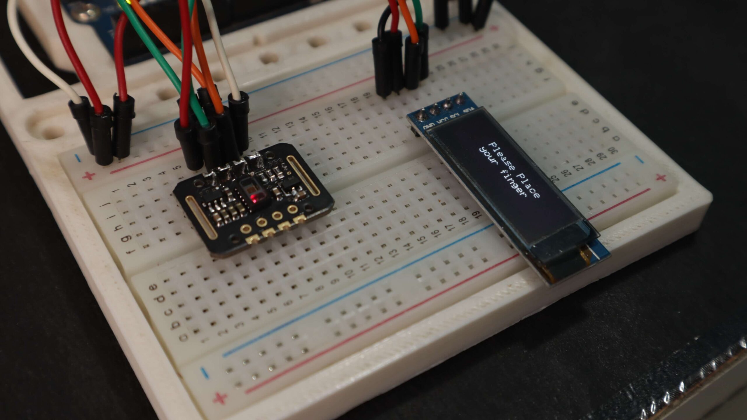
#include <Adafruit_GFX.h> // OLED libraries #include <Adafruit_SSD1306.h> #include <Wire.h> #include "MAX30105.h" // MAX3010x library #include "heartRate.h" // Heart rate calculating algorithm MAX30105 particleSensor; const byte RATE_SIZE = 4; // Increase this for more averaging. 4 is good. byte rates[RATE_SIZE]; // Array of heart rates byte rateSpot = 0; long lastBeat = 0; // Time at which the last beat occurred float beatsPerMinute; int beatAvg; #define SCREEN_WIDTH 128 // OLED display width, in pixels #define SCREEN_HEIGHT 32 // OLED display height, in pixels #define OLED_RESET -1 // Reset pin # (or -1 if sharing Arduino reset pin) Adafruit_SSD1306 display(SCREEN_WIDTH, SCREEN_HEIGHT, &Wire, OLED_RESET); // Declaring the display name (display) static const unsigned char PROGMEM logo2_bmp[] = { 0x03, 0xC0, 0xF0, 0x06, 0x71, 0x8C, 0x0C, 0x1B, 0x06, 0x18, 0x0E, 0x02, 0x10, 0x0C, 0x03, 0x10, // Logo2 and Logo3 are two bmp pictures that display on the OLED if called 0x04, 0x01, 0x10, 0x04, 0x01, 0x10, 0x40, 0x01, 0x10, 0x40, 0x01, 0x10, 0xC0, 0x03, 0x08, 0x88, 0x02, 0x08, 0xB8, 0x04, 0xFF, 0x37, 0x08, 0x01, 0x30, 0x18, 0x01, 0x90, 0x30, 0x00, 0xC0, 0x60, 0x00, 0x60, 0xC0, 0x00, 0x31, 0x80, 0x00, 0x1B, 0x00, 0x00, 0x0E, 0x00, 0x00, 0x04, 0x00, }; static const unsigned char PROGMEM logo3_bmp[] = { 0x01, 0xF0, 0x0F, 0x80, 0x06, 0x1C, 0x38, 0x60, 0x18, 0x06, 0x60, 0x18, 0x10, 0x01, 0x80, 0x08, 0x20, 0x01, 0x80, 0x04, 0x40, 0x00, 0x00, 0x02, 0x40, 0x00, 0x00, 0x02, 0xC0, 0x00, 0x08, 0x03, 0x80, 0x00, 0x08, 0x01, 0x80, 0x00, 0x18, 0x01, 0x80, 0x00, 0x1C, 0x01, 0x80, 0x00, 0x14, 0x00, 0x80, 0x00, 0x14, 0x00, 0x80, 0x00, 0x14, 0x00, 0x40, 0x10, 0x12, 0x00, 0x40, 0x10, 0x12, 0x00, 0x7E, 0x1F, 0x23, 0xFE, 0x03, 0x31, 0xA0, 0x04, 0x01, 0xA0, 0xA0, 0x0C, 0x00, 0xA0, 0xA0, 0x08, 0x00, 0x60, 0xE0, 0x10, 0x00, 0x20, 0x60, 0x20, 0x06, 0x00, 0x40, 0x60, 0x03, 0x00, 0x40, 0xC0, 0x01, 0x80, 0x01, 0x80, 0x00, 0xC0, 0x03, 0x00, 0x00, 0x60, 0x06, 0x00, 0x00, 0x30, 0x0C, 0x00, 0x00, 0x08, 0x10, 0x00, 0x00, 0x06, 0x60, 0x00, 0x00, 0x03, 0xC0, 0x00, 0x00, 0x01, 0x80, 0x00 }; void setup() { display.begin(SSD1306_SWITCHCAPVCC, 0x3C); // Start the OLED display display.display(); delay(3000); // Initialize sensor particleSensor.begin(Wire, I2C_SPEED_FAST); // Use default I2C port, 400kHz speed particleSensor.setup(); // Configure sensor with default settings particleSensor.setPulseAmplitudeRed(0x0A); // Turn Red LED to low to indicate sensor is running } void loop() { long irValue = particleSensor.getIR(); // Reading the IR value to check if there's a finger on the sensor or not, also detecting a heartbeat if (irValue > 7000) { // If a finger is detected display.clearDisplay(); // Clear the display display.drawBitmap(5, 5, logo2_bmp, 24, 21, WHITE); // Draw the first bmp picture (little heart) display.setTextSize(2); // Near it, display the average BPM display.setTextColor(WHITE); display.setCursor(50, 0); display.println("BPM"); display.setCursor(50, 18); display.println(beatAvg); display.display(); if (checkForBeat(irValue) == true) { // If a heart beat is detected display.clearDisplay(); // Clear the display display.drawBitmap(0, 0, logo3_bmp, 32, 32, WHITE); // Draw the second picture (bigger heart) display.setTextSize(2); // And still display the average BPM display.setTextColor(WHITE); display.setCursor(50, 0); display.println("BPM"); display.setCursor(50, 18); display.println(beatAvg); display.display(); tone(3, 1000); // Tone the buzzer for 100ms (you can reduce it) delay(100); noTone(3); // Deactivate the buzzer to have the effect of a "bip" // We sensed a beat! long delta = millis() - lastBeat; // Measure duration between two beats lastBeat = millis(); beatsPerMinute = 60 / (delta / 1000.0); // Calculating the BPM if (beatsPerMinute < 255 && beatsPerMinute > 20) { // To calculate the average, we store some values (4) then do some math to calculate the average rates[rateSpot++] = (byte)beatsPerMinute; // Store this reading in the array rateSpot %= RATE_SIZE; // Wrap variable // Take average of readings beatAvg = 0; for (byte x = 0; x < RATE_SIZE; x++) beatAvg += rates[x]; beatAvg /= RATE_SIZE; } } } if (irValue < 7000) { // If no finger is detected, it informs the user and puts the average BPM to 0 or it will be stored for the next measure beatAvg = 0; display.clearDisplay(); display.setTextSize(1); display.setTextColor(WHITE); display.setCursor(30, 5); display.println("Please Place "); display.setCursor(30, 15); display.println("your finger "); display.display(); noTone(3); } } |
Copy the following code and upload it to the Arduino Board.
Working
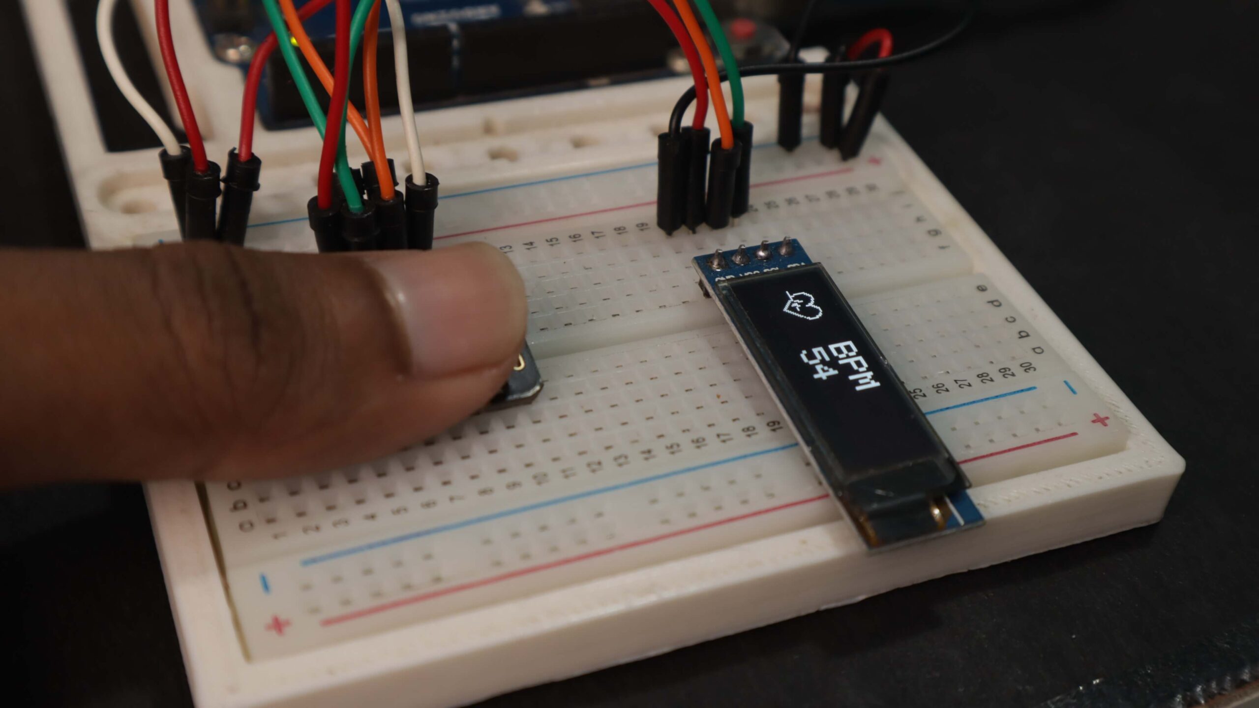
After uploading the code, Put your finger on the sensor and wait for a while after a few seconds display shows the reading Value of your BPM or the heart pictures changed in sync with your heartbeats.


