In this tutorial, we will show you how to use MAX485 MODBUS Serial Communication With Arduino. We will use the Arduino nano board and the MODBUS protocol, the RS-485 is a standard for serial data communication. It is used for industrial communication between electronic devices. MODBUS is a popular network protocol system used in industrial applications.
We will also be building a simple MODBUS master and slave in order to show you how the protocol works. It is simple and robust.
The RS-485 module is used in a variety of applications such as industrial automation, building automation, and networking. Check out How To Use MCP2515 SPI CAN Bus Module With Arduino
Required Components
- Arduino Nano
- MAX485 Module
- Breadboard
- Jumper wires
- Led
- Buttons
What is RS-485?
The RS-485 is a standard for serial data communication. This standard was developed by the Electronic Industries Alliance (EIA) and is now maintained by the Telecommunications Industry Association (TIA). The RS-485 standard supports data rates up to 10 Mbps.
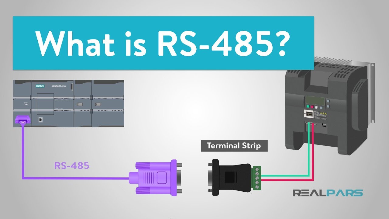
RS-485 is a communication standard that allows devices to send and receive data over long distances using a two-pair cable. It is generally used in industrial locations where devices are spread out over a large area and need to communicate with each other.
RS-485 is frequently used in systems that need multiple devices to rapidly transfer data over long distances, such as in process control systems or manufacturer automation systems.
Reasons to use RS-485
Long-distance communication: RS-485 is developed for communication over long distances up to 4000 feet or 1200 meters without loss of data. This makes it an optimal choice for industrial and commercial locations where devices may be applied over extended spaces.
Multiple devices: Unlike RS-232, RS-485 supports multiple wired devices on a transferred communications bus, and each device has a unique address. This allows us to add new devices to an existing system without changing the structure of the entire system.
High speed: RS-485 can support high-speed communication up to 10 Mbps. This feature makes it perfect for applications that need high-speed data transfer, such as machine control systems.
Cost-effective: RS-485 is a widely used communication standard, the cost of equipment is relatively inexpensive, which makes it the best option for applications that require reliable communication over long distances without breaking the budget.
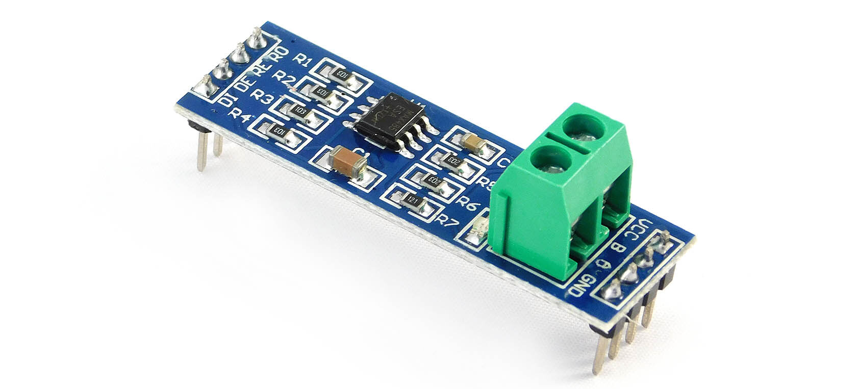
MAX485 TTL to RS485 Converter Module
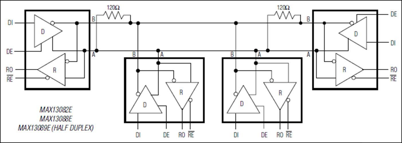
The MAX485 TTL to RS485 Converter Module is a hardware module that enables the communication between TTL-level devices, such as an Arduino or Raspberry microcontroller, and RS485 communication networks. In RS-485, the data is transmitted using two wires, one for transmitting and one for receiving data, and the signals are transferred differentially.
the module is designed to convert the TTL-level signals into RS485-compatible signals that can be transmitted over long distances (up to 1200 meters or 4000 feet) without signal loss. it supports up to 2.5Mbps data rates, but as distance goes up, the maximum data rate that can be supported comes down.
The MAX485 chip is used as the primary component on the module, which converts the TTL-level signals into RS485-compatible signals.
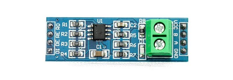
Pinout of Max 485 TTL To RS485 Converter Module
| Pin Number | Pin Name | Function |
|---|---|---|
| 1 | VCC | Power supply input (5V) |
| 2 | GND | Ground |
| 3 | DI/TX | Data input (TTL level) / Transmit data (RS485 level) |
| 4 | RO/RX | Data output (TTL level) / Receive data (RS485 level) |
| 5 | DE | Data enable (active low) |
| 6 | RE | Receiver enable (active low) |
| 7 | A | RS485 differential signal A |
| 8 | B | RS485 differential signal B |
Note – Note that the DI/TX pin and RO/RX pin is labeled as such because they can function as either a TTL-level data input/output.
Features of MAX485 TTL to RS485 Converter Module
- Converts TTL signals to RS485 signals and vice versa.
- Easy to Use
- Half-Duplex Communication:
- Supports Multi-Point Communication
- Low Power Consumption
- Reliable Communication
- Cost-Effective Solution
Specification of MAX485 TTL to RS485 Converter Module
- Operating voltage: 5V DC
- Maximum data rate: 2.5 Mbps
- Maximum distance: up to 1200 meters (depending on cable quality and other factors)
- Onboard data enable (DE) and receiver enable (RE) control pins
- Half-duplex operation
- 1 driver and up to 32 receivers on the bus
- ESD protection up to ±15 kV (Human Body Model)
- Operating temperature range: -40°C to +85°C
- Dimensions: 44 x 14mm
- LED Power indicator
Application of MAX485 TTL to RS485 Converter Module
- Industrial Automation
- Building Automation
- Energy Management Systems
- Access Control Systems
- Medical Equipment
- Transportation Systems
Multi-Drop Support for Multiple Devices
RS-485 serial connection allows you to connect multiple devices (up to 32) to one communication line generally referred to as ‘multi-drop’. Each device has a unique address and can send and receive data. This is called a multi-drop configuration.
It is helpful in problems where long-distance communication is required, such as in factories or buildings. Only one device can send data at a time and the others listen. When a device sends data, only the one with the correct address responds. This makes communication between many devices easy and reliable.
The devices are usually configured in a Master / Slave mode with a Master device and more than one Slave device. Because they are on the same bus, to avoid any possible conflict, generally, the Slave devices only talk when they are asked for some help from the Master such as requesting a temperature reading.
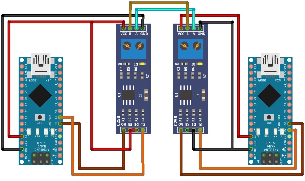
Interfacing MAX485 MODBUS Serial Communication With Arduino
Example code – MAX485 MODBUS Serial Communication With Arduino
Code for Transmitter
|
1 2 3 4 5 6 7 8 9 10 11 12 |
#include <SoftwareSerial.h> SoftwareSerial mySerial(3,2); void setup() { mySerial.begin (9600); Serial.begin(9600); } void loop() { mySerial.println ("DIY Projects Lab !"); Serial.println ("Hey !"); delay(1000); } |
Code for Reciever
|
1 2 3 4 5 6 7 8 9 10 11 12 13 |
#include <SoftwareSerial.h> SoftwareSerial mySerial(3,2); void setup() { Serial.begin(9600); mySerial.begin(9600); } void loop() { while(mySerial.available() > 0){ char c = mySerial.read(); Serial.write(c); } } |
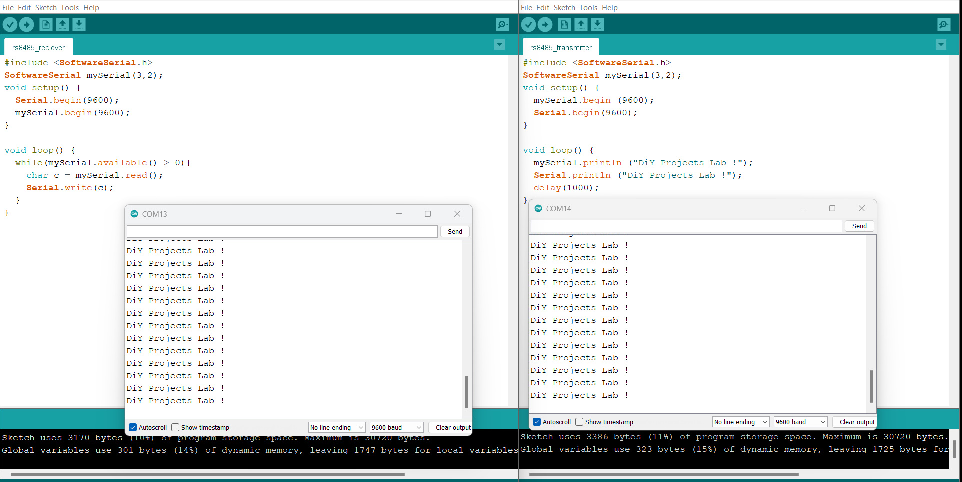
Serial Monitor
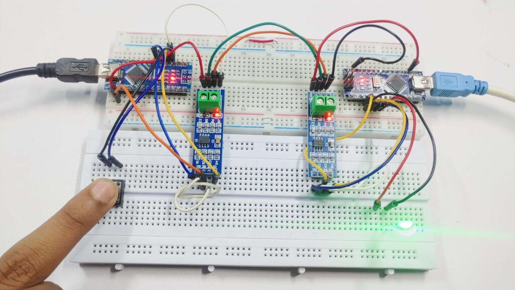
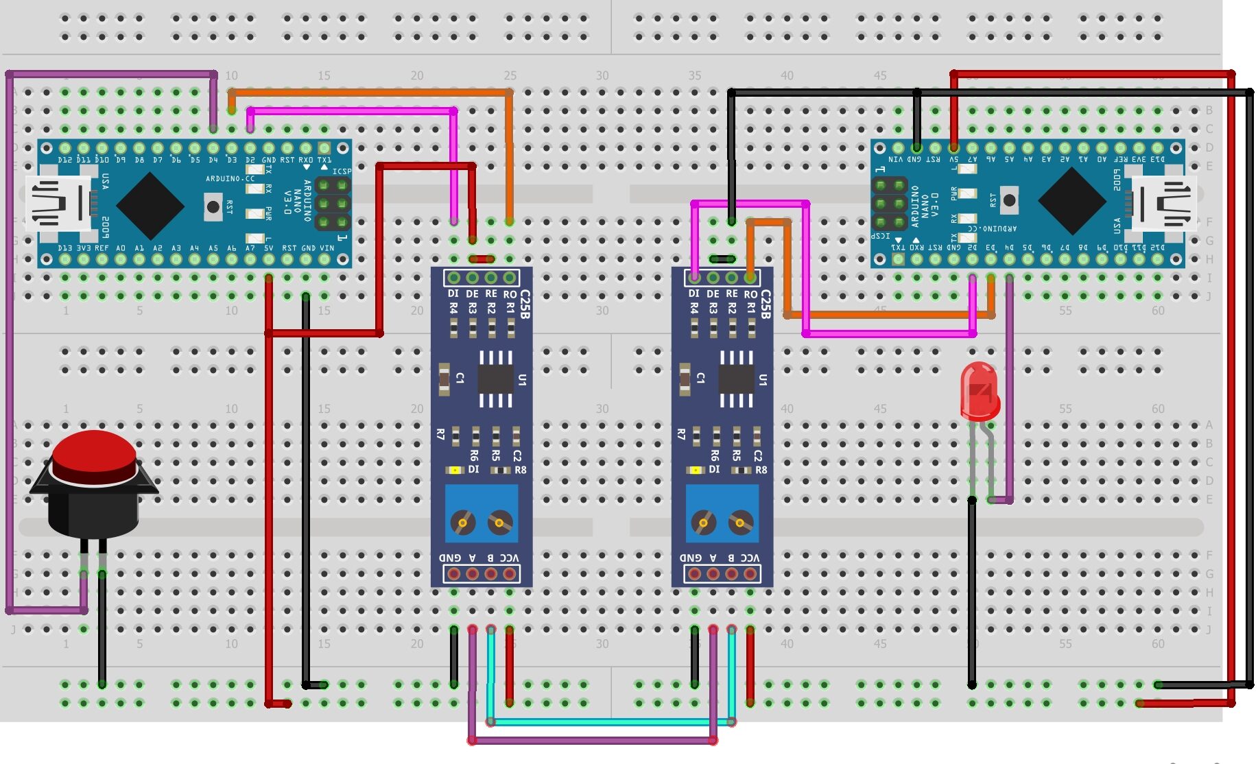
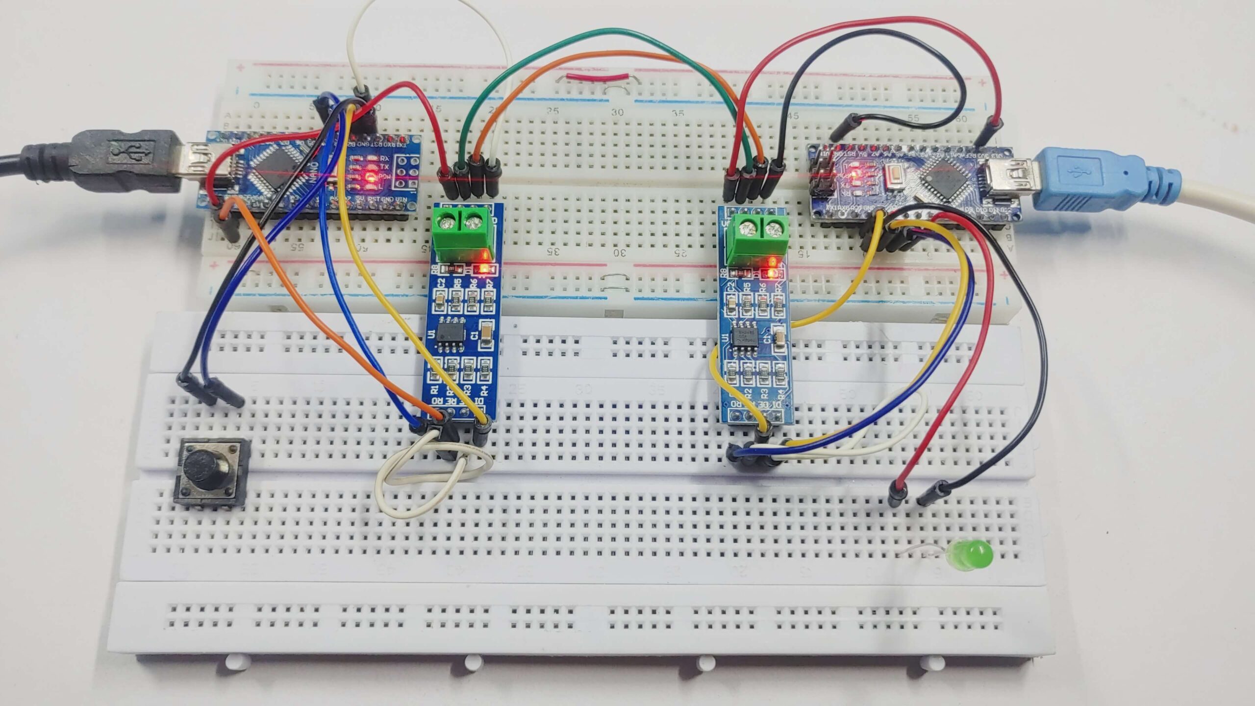
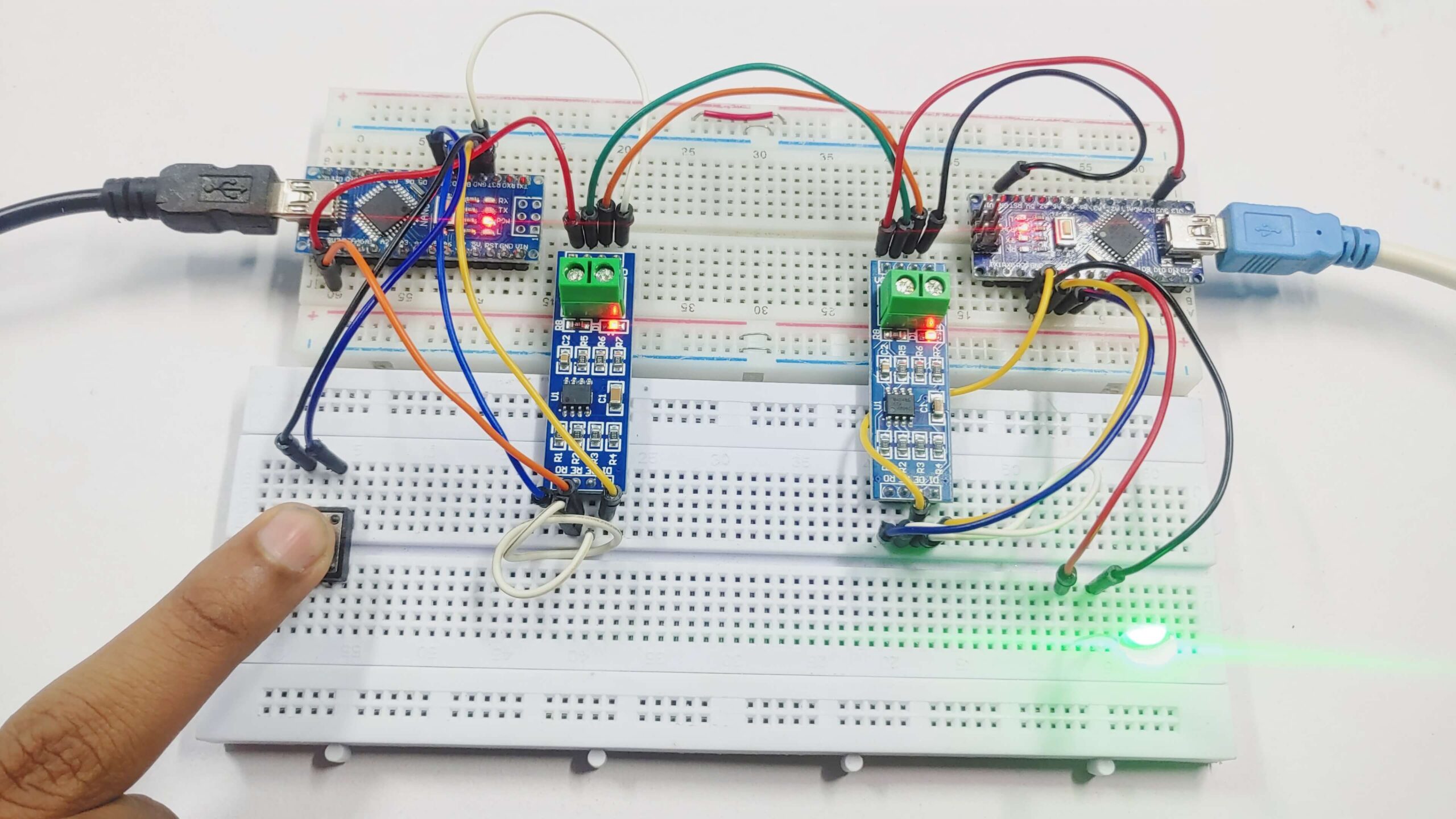
Control LED Using Push Button With MAX485 MODBUS Serial Communication & Arduino
Wiring between RS-485 and Arduino Nano (Master)
| RS-485 Pin | Arduino Nano |
|---|---|
| DI (Data In) | 2 |
| DE (Data Enable) | 5V |
| RE (Receiver Enable) | 5V |
| RO (Data Out) | 3 |
| VCC | 5V |
| GND | GND |
| A | To A of Slave RS-485 |
| B | To B of Slave RS-485 |
Push Button to Arduino
| switch | Arduino Nano |
|---|---|
| Button Pin | 4 |
Wiring between RS-485 and Arduino Nano (Slave)
| RS-485 Pin | Arduino Nano |
|---|---|
| DI (Data In) | 2 |
| DE (Data Enable) | GND |
| RE (Receiver Enable) | GND |
| RO (Data Out) | 3 |
| VCC | 5V |
| GND | GND |
| A | To A of Slave RS-485 |
| B | To B of Slave RS-485 |
LED To Arduino
| LED | Arduino Nano |
|---|---|
| Positive Terminal | 4 |
| Negative Terminal | GND |
Source Code – MAX485 MODBUS Serial Communication With Arduino
Master RS-485 Device Software
|
1 2 3 4 5 6 7 8 9 10 11 12 13 14 15 16 17 18 |
#include <SoftwareSerial.h> SoftwareSerial mySerial(3, 2); // RX, TX pins for the wireless module int buttonPin = 4; // button connected to pin 4 void setup() { mySerial.begin(9600); pinMode(buttonPin, INPUT_PULLUP); // set pin 4 as input with internal pull-up resistor } void loop() { if (digitalRead(buttonPin) == LOW) { // if the button is pressed mySerial.write('1'); // send '1' character to turn on the LED } else { mySerial.write('0'); // send '0' character to turn off the LED } delay(100); // add a small delay to debounce the button } |
Slave RS-485 Device Software
|
1 2 3 4 5 6 7 8 9 10 11 12 13 14 15 16 17 18 19 20 21 22 |
#include <SoftwareSerial.h> SoftwareSerial mySerial(3, 2); int ledPin = 4; // LED connected to pin 4 void setup() { Serial.begin(9600); mySerial.begin(9600); pinMode(ledPin, OUTPUT); // set pin 4 as output } void loop() { while (mySerial.available() > 0) { char c = mySerial.read(); Serial.write(c); if (c == '1') { // if the received character is '1', turn on the LED digitalWrite(ledPin, HIGH); } else if (c == '0') { // if the received character is '0', turn off the LED digitalWrite(ledPin, LOW); } } } |
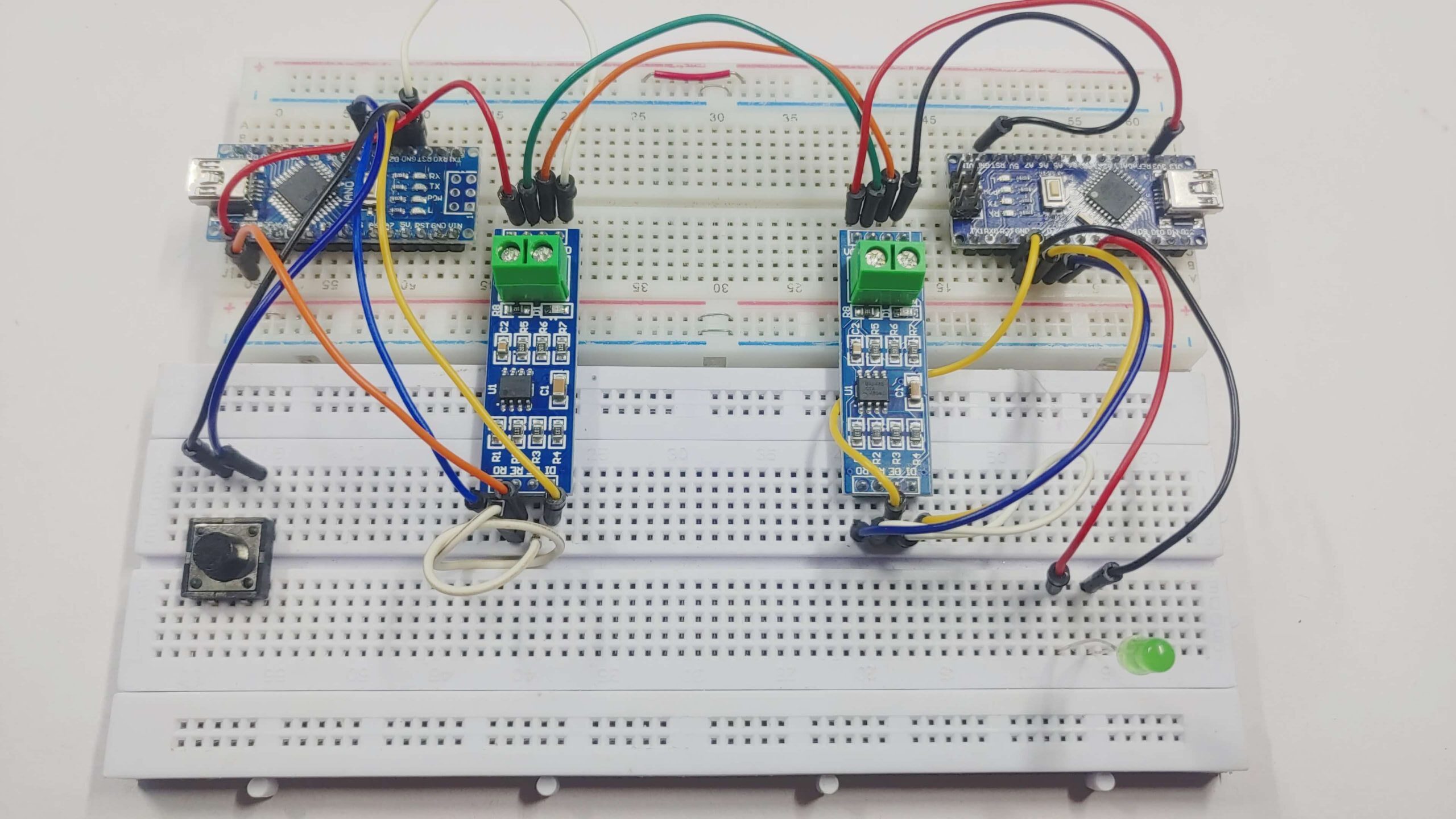
Working

