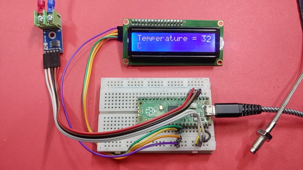
This is a tutorial on how to use a K-Type Thermocouple MAX6675 Amplifier With Raspberry Pi Pico. The k-type thermocouple is a temperature sensor that can be used to measure temperatures from 0°C to
+700°C. with 0.25°C accuracy. MAX6675 amplifier is used to amplify the signal from the thermocouple and convert it to a digital signal that can be read by the Raspberry Pi Pico.
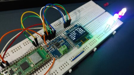
We’ll then use that data to display the current temperature on display. By the end of this tutorial, you will be able to read temperature data from a K-Type Thermocouple MAX6675 Amplifier with Raspberry Pi Pico and display data on the OLED display.
Thank You, PCBWay:
This project is successfully completed because of the support and help from PCBWay. Guys if you have a PCB project, please see their website and get exciting bargains and coupons.
PCBway is the best prototype PCB company offering great PCB boards at lower prices If you sign-up using this link you will get beginner and sign-up coupon rewards. https://www.pcbway.com
Required Material
- Raspberry Pi Pico
- K-Type thermocouple probe
- MAX6675 amplifier
- Breadboard
- Jumper wires
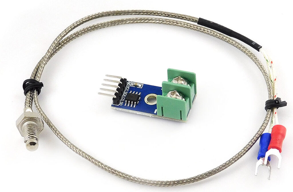
MAX7765 K-Type Thermocouple Temperature Sensor
The MAX6675 module, along with a K-Type thermocouple sensor, is a device that measures temperature very accurately. it offers a digital serial interface that is compatible with Raspberry Pi Pico. It uses a Maxim MAX6675 K-Thermocouple to digital converter IC, which converts the signals from the thermocouple into digital data that a microcontroller can understand.
The MAX6675 module has a high resolution, which means it can measure temperature with precision up to 0.25°C. It can handle temperatures as high as +1024°C. For temperatures between 0°C and +700°C, it has good accuracy and provides reliable temperature readings.
Pinout of K-Type Thermocouple Temperature Sensor
- VCC: Power supply
- GND: Ground
- SCK: Serial Clock
- CS: Chip Select
- SO: Serial Data
Specification of K-Type Thermocouple Temperature Sensor
- Amplifier IC: MAX6675
- Supply Voltage: 3.3 – 5V
- Current: 50mA
- Temperature Range: 0 – 600°C
- Temperature Resolution: 0.25°C
- Working Temperature: -20°C to 85°C
- Size: 32×16 mm
- Thermocouple Type: K-Type
- Pinout: GND, VCC, SCK, CS, SO
- Conversion Time: 220 ms
- Interface: SPI compatible
- Accuracy: ±2°C within 0°C to +700°C
- Resolution: 12-bit
- Digital Output Format: Temperature readings in digital format
Applications of K-Type Thermocouple Temperature Sensor
- Industrial temperature measurement
- HVAC systems
- Food industry
- Automotive temperature monitoring
- Research and development
- Energy management
- Aerospace and aviation
- Environmental monitoring
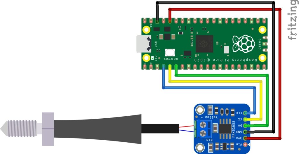
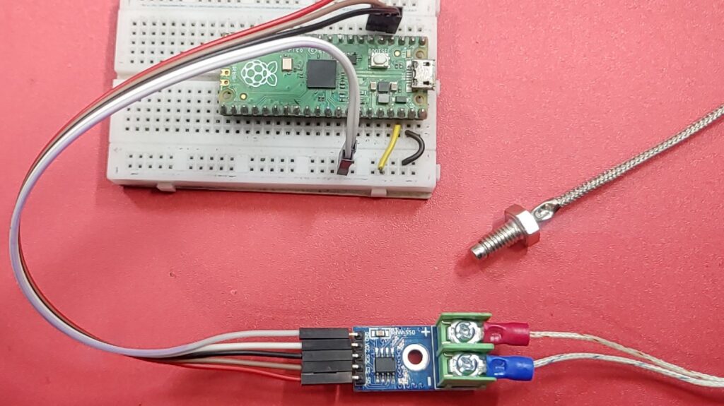
Circuit Diagram: MAX6675 & Raspberry Pi Pico
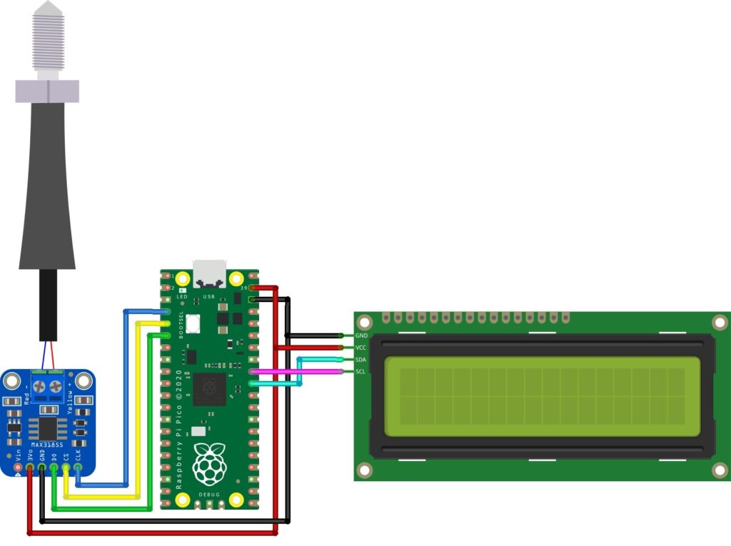
Connect the MAX6675 to Raspberry Pi Pico
MAX6675 —-> Raspberry Pi Pico
- VCC –> 3.3V
- GND –> GND
- SO –> 4
- CS –> 3
- CLK –> 2
MicroPython Library For MAX6675 & Raspberry Pi Pico
Below is the source code/program for interfacing MAX6675 with Raspberry Pi Pico. To upload the code, make sure you have the max6675.py. Copy the code and paste it into the Thonny IDE. and save it with the name max6675.py
max6675.py
|
1 2 3 4 5 6 7 8 9 10 11 12 13 14 15 16 17 18 19 20 21 22 23 24 25 26 27 28 29 30 31 32 33 34 35 36 37 38 39 40 41 42 43 44 45 46 47 48 49 50 51 52 53 54 55 56 57 58 59 60 61 62 63 64 65 66 67 68 69 70 71 72 73 74 75 76 77 78 79 80 81 82 83 84 85 86 87 88 89 90 91 92 93 94 95 96 97 |
import time class MAX6675: MEASUREMENT_PERIOD_MS = 220 def __init__(self, sck, cs, so): """ Creates a new object for controlling MAX6675 :param sck: SCK (clock) pin, must be configured as Pin.OUT :param cs: CS (select) pin, must be configured as Pin.OUT :param so: SO (data) pin, must be configured as Pin.IN """ # Thermocouple self._sck = sck self._sck.low() self._cs = cs self._cs.high() self._so = so self._so.low() self._last_measurement_start = 0 self._last_read_temp = 0 self._error = 0 def _cycle_sck(self): """ Helper method to cycle the SCK (clock) signal. """ self._sck.high() time.sleep_us(1) self._sck.low() time.sleep_us(1) def refresh(self): """ Start a new measurement. """ self._cs.low() time.sleep_us(10) self._cs.high() self._last_measurement_start = time.ticks_ms() def ready(self): """ Signals if the measurement is finished. :return: True if the measurement is ready for reading. """ return time.ticks_ms() - self._last_measurement_start > MAX6675.MEASUREMENT_PERIOD_MS def error(self): """ Returns the error bit of the last reading. If this bit is set (=1), there's a problem with the thermocouple - it can be damaged or loosely connected. :return: Error bit value """ return self._error def read(self): """ Reads the last measurement and starts a new one. If a new measurement is not ready yet, it returns the last value. Note: The last measurement can be quite old (e.g., since the last call to `read`). To refresh the measurement, call `refresh` and wait for `ready` to become True before reading. :return: Measured temperature """ # Check if a new reading is available if self.ready(): # Bring CS pin low to start the protocol for reading the result of # the conversion process. Forcing the pin down outputs # the first (dummy) sign bit 15. self._cs.low() time.sleep_us(10) # Read temperature bits 14-3 from MAX6675. value = 0 for i in range(12): # SCK should resemble the clock signal, and the new SO value # is presented at the falling edge. self._cycle_sck() value += self._so.value() << (11 - i) # Read the TC Input pin to check if the input is open. self._cycle_sck() self._error = self._so.value() # Read the last two bits to complete the protocol. for i in range(2): self._cycle_sck() # Finish the protocol and start a new measurement. self._cs.high() self._last_measurement_start = time.ticks_ms() self._last_read_temp = value * 0.25 return self._last_read_temp |
main.py
|
1 2 3 4 5 6 7 8 9 10 11 12 13 |
from max6675 import MAX6675 from machine import Pin import time sck = Pin(2, Pin.OUT) # Initialize the clock pin (SCK) as an output pin cs = Pin(3, Pin.OUT) # Initialize the chip select pin (CS) as an output pin so = Pin(4, Pin.IN) # Initialize the data input pin (SO) as an input pin sensor = MAX6675(sck, cs, so) # Create an instance of the MAX6675 class with the specified pins while True: print("Temperature =", sensor.read()) # Read and print the temperature value from the sensor time.sleep(1) # Pause for 1 second |
Working
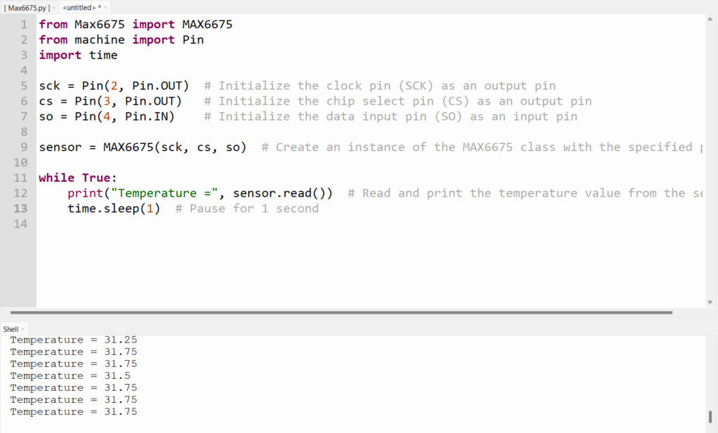
Once you’ve run the code, you’ll be able to view the sensor output in the Shell of the Thonny IDE. Refer to the image below.
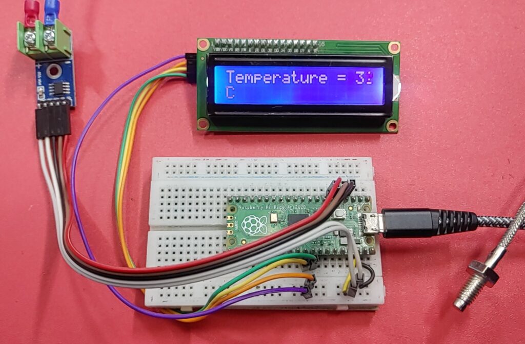
Interfacing MAX6675 Thermocouple & LCD Display with Raspberry Pi Pico
Micropython Library
lcd_api.py
|
1 2 3 4 5 6 7 8 9 10 11 12 13 14 15 16 17 18 19 20 21 22 23 24 25 26 27 28 29 30 31 32 33 34 35 36 37 38 39 40 41 42 43 44 45 46 47 48 49 50 51 52 53 54 55 56 57 58 59 60 61 62 63 64 65 66 67 68 69 70 71 72 73 74 75 76 77 78 79 80 81 82 83 84 85 86 87 88 89 90 91 92 93 94 95 96 97 98 99 100 101 102 103 104 105 106 107 108 109 110 111 112 113 114 115 116 117 118 119 120 121 122 123 124 125 126 127 128 129 130 131 132 133 134 135 136 137 138 139 140 141 142 143 144 145 146 147 148 149 150 151 152 153 154 155 156 157 158 159 160 161 162 163 164 165 166 167 168 169 170 171 172 173 174 175 176 177 178 179 180 181 182 183 184 185 186 187 188 189 190 191 192 193 194 195 |
"""Provides an API for talking to HD44780 compatible character LCDs.""" import time class LcdApi: """Implements the API for talking with HD44780 compatible character LCDs. This class only knows what commands to send to the LCD, and not how to get them to the LCD. It is expected that a derived class will implement the hal_xxx functions. """ # The following constant names were lifted from the avrlib lcd.h # header file, however, I changed the definitions from bit numbers # to bit masks. # # HD44780 LCD controller command set LCD_CLR = 0x01 # DB0: clear display LCD_HOME = 0x02 # DB1: return to home position LCD_ENTRY_MODE = 0x04 # DB2: set entry mode LCD_ENTRY_INC = 0x02 # --DB1: increment LCD_ENTRY_SHIFT = 0x01 # --DB0: shift LCD_ON_CTRL = 0x08 # DB3: turn lcd/cursor on LCD_ON_DISPLAY = 0x04 # --DB2: turn display on LCD_ON_CURSOR = 0x02 # --DB1: turn cursor on LCD_ON_BLINK = 0x01 # --DB0: blinking cursor LCD_MOVE = 0x10 # DB4: move cursor/display LCD_MOVE_DISP = 0x08 # --DB3: move display (0-> move cursor) LCD_MOVE_RIGHT = 0x04 # --DB2: move right (0-> left) LCD_FUNCTION = 0x20 # DB5: function set LCD_FUNCTION_8BIT = 0x10 # --DB4: set 8BIT mode (0->4BIT mode) LCD_FUNCTION_2LINES = 0x08 # --DB3: two lines (0->one line) LCD_FUNCTION_10DOTS = 0x04 # --DB2: 5x10 font (0->5x7 font) LCD_FUNCTION_RESET = 0x30 # See "Initializing by Instruction" section LCD_CGRAM = 0x40 # DB6: set CG RAM address LCD_DDRAM = 0x80 # DB7: set DD RAM address LCD_RS_CMD = 0 LCD_RS_DATA = 1 LCD_RW_WRITE = 0 LCD_RW_READ = 1 def __init__(self, num_lines, num_columns): self.num_lines = num_lines if self.num_lines > 4: self.num_lines = 4 self.num_columns = num_columns if self.num_columns > 40: self.num_columns = 40 self.cursor_x = 0 self.cursor_y = 0 self.backlight = True self.display_off() self.backlight_on() self.clear() self.hal_write_command(self.LCD_ENTRY_MODE | self.LCD_ENTRY_INC) self.hide_cursor() self.display_on() def clear(self): """Clears the LCD display and moves the cursor to the top left corner. """ self.hal_write_command(self.LCD_CLR) self.hal_write_command(self.LCD_HOME) self.cursor_x = 0 self.cursor_y = 0 def show_cursor(self): """Causes the cursor to be made visible.""" self.hal_write_command(self.LCD_ON_CTRL | self.LCD_ON_DISPLAY | self.LCD_ON_CURSOR) def hide_cursor(self): """Causes the cursor to be hidden.""" self.hal_write_command(self.LCD_ON_CTRL | self.LCD_ON_DISPLAY) def blink_cursor_on(self): """Turns on the cursor, and makes it blink.""" self.hal_write_command(self.LCD_ON_CTRL | self.LCD_ON_DISPLAY | self.LCD_ON_CURSOR | self.LCD_ON_BLINK) def blink_cursor_off(self): """Turns on the cursor, and makes it no blink (i.e. be solid).""" self.hal_write_command(self.LCD_ON_CTRL | self.LCD_ON_DISPLAY | self.LCD_ON_CURSOR) def display_on(self): """Turns on (i.e. unblanks) the LCD.""" self.hal_write_command(self.LCD_ON_CTRL | self.LCD_ON_DISPLAY) def display_off(self): """Turns off (i.e. blanks) the LCD.""" self.hal_write_command(self.LCD_ON_CTRL) def backlight_on(self): """Turns the backlight on. This isn't really an LCD command, but some modules have backlight controls, so this allows the hal to pass through the command. """ self.backlight = True self.hal_backlight_on() def backlight_off(self): """Turns the backlight off. This isn't really an LCD command, but some modules have backlight controls, so this allows the hal to pass through the command. """ self.backlight = False self.hal_backlight_off() def move_to(self, cursor_x, cursor_y): """Moves the cursor position to the indicated position. The cursor position is zero based (i.e. cursor_x == 0 indicates first column). """ self.cursor_x = cursor_x self.cursor_y = cursor_y addr = cursor_x & 0x3f if cursor_y & 1: addr += 0x40 # Lines 1 & 3 add 0x40 if cursor_y & 2: addr += 0x14 # Lines 2 & 3 add 0x14 self.hal_write_command(self.LCD_DDRAM | addr) def putchar(self, char): """Writes the indicated character to the LCD at the current cursor position, and advances the cursor by one position. """ if char != '\n': self.hal_write_data(ord(char)) self.cursor_x += 1 if self.cursor_x >= self.num_columns or char == '\n': self.cursor_x = 0 self.cursor_y += 1 if self.cursor_y >= self.num_lines: self.cursor_y = 0 self.move_to(self.cursor_x, self.cursor_y) def putstr(self, string): """Write the indicated string to the LCD at the current cursor position and advances the cursor position appropriately. """ for char in string: self.putchar(char) def custom_char(self, location, charmap): """Write a character to one of the 8 CGRAM locations, available as chr(0) through chr(7). """ location &= 0x7 self.hal_write_command(self.LCD_CGRAM | (location << 3)) time.sleep_us(40) for i in range(8): self.hal_write_data(charmap[i]) time.sleep_us(40) self.move_to(self.cursor_x, self.cursor_y) def hal_backlight_on(self): """Allows the hal layer to turn the backlight on. If desired, a derived HAL class will implement this function. """ pass def hal_backlight_off(self): """Allows the hal layer to turn the backlight off. If desired, a derived HAL class will implement this function. """ pass def hal_write_command(self, cmd): """Write a command to the LCD. It is expected that a derived HAL class will implement this function. """ raise NotImplementedError def hal_write_data(self, data): """Write data to the LCD. It is expected that a derived HAL class will implement this function. """ raise NotImplementedError |
i2c_lcd.py
|
1 2 3 4 5 6 7 8 9 10 11 12 13 14 15 16 17 18 19 20 21 22 23 24 25 26 27 28 29 30 31 32 33 34 35 36 37 38 39 40 41 42 43 44 45 46 47 48 49 50 51 52 53 54 55 56 57 58 59 60 61 62 63 64 65 66 67 68 69 70 71 72 73 74 75 76 77 78 79 80 |
from lcd_api import LcdApi from machine import I2C from time import sleep_ms # The PCF8574 has a jumper selectable address: 0x20 - 0x27 DEFAULT_I2C_ADDR = 0x27 # Defines shifts or masks for the various LCD line attached to the PCF8574 MASK_RS = 0x01 MASK_RW = 0x02 MASK_E = 0x04 SHIFT_BACKLIGHT = 3 SHIFT_DATA = 4 class I2cLcd(LcdApi): """Implements a HD44780 character LCD connected via PCF8574 on I2C.""" def __init__(self, i2c, i2c_addr, num_lines, num_columns): self.i2c = i2c self.i2c_addr = i2c_addr self.i2c.writeto(self.i2c_addr, bytearray([0])) sleep_ms(20) # Allow LCD time to powerup # Send reset 3 times self.hal_write_init_nibble(self.LCD_FUNCTION_RESET) sleep_ms(5) # need to delay at least 4.1 msec self.hal_write_init_nibble(self.LCD_FUNCTION_RESET) sleep_ms(1) self.hal_write_init_nibble(self.LCD_FUNCTION_RESET) sleep_ms(1) # Put LCD into 4 bit mode self.hal_write_init_nibble(self.LCD_FUNCTION) sleep_ms(1) LcdApi.__init__(self, num_lines, num_columns) cmd = self.LCD_FUNCTION if num_lines > 1: cmd |= self.LCD_FUNCTION_2LINES self.hal_write_command(cmd) def hal_write_init_nibble(self, nibble): """Writes an initialization nibble to the LCD. This particular function is only used during initialization. """ byte = ((nibble >> 4) & 0x0f) << SHIFT_DATA self.i2c.writeto(self.i2c_addr, bytearray([byte | MASK_E])) self.i2c.writeto(self.i2c_addr, bytearray([byte])) def hal_backlight_on(self): """Allows the hal layer to turn the backlight on.""" self.i2c.writeto(self.i2c_addr, bytearray([1 << SHIFT_BACKLIGHT])) def hal_backlight_off(self): """Allows the hal layer to turn the backlight off.""" self.i2c.writeto(self.i2c_addr, bytearray([0])) def hal_write_command(self, cmd): """Writes a command to the LCD. Data is latched on the falling edge of E. """ byte = ((self.backlight << SHIFT_BACKLIGHT) | (((cmd >> 4) & 0x0f) << SHIFT_DATA)) self.i2c.writeto(self.i2c_addr, bytearray([byte | MASK_E])) self.i2c.writeto(self.i2c_addr, bytearray([byte])) byte = ((self.backlight << SHIFT_BACKLIGHT) | ((cmd & 0x0f) << SHIFT_DATA)) self.i2c.writeto(self.i2c_addr, bytearray([byte | MASK_E])) self.i2c.writeto(self.i2c_addr, bytearray([byte])) if cmd <= 3: # The home and clear commands require a worst case delay of 4.1 msec sleep_ms(5) def hal_write_data(self, data): """Write data to the LCD.""" byte = (MASK_RS | (self.backlight << SHIFT_BACKLIGHT) | (((data >> 4) & 0x0f) << SHIFT_DATA)) self.i2c.writeto(self.i2c_addr, bytearray([byte | MASK_E])) self.i2c.writeto(self.i2c_addr, bytearray([byte])) byte = (MASK_RS | (self.backlight << SHIFT_BACKLIGHT) | ((data & 0x0f) << SHIFT_DATA)) self.i2c.writeto(self.i2c_addr, bytearray([byte | MASK_E])) self.i2c.writeto(self.i2c_addr, bytearray([byte])) |
main.py
|
1 2 3 4 5 6 7 8 9 10 11 12 13 14 15 16 17 18 19 20 21 22 23 24 25 26 |
from max6675 import MAX6675 from machine import Pin, I2C from lcd_api import LcdApi from i2c_lcd import I2cLcd import time sck = Pin(2, Pin.OUT) cs = Pin(3, Pin.OUT) so = Pin(4, Pin.IN) sensor = MAX6675(sck, cs, so) I2C_ADDR = 0x27 I2C_NUM_ROWS = 2 I2C_NUM_COLS = 16 i2c = I2C(1, sda=Pin(26), scl=Pin(27), freq=400000) lcd = I2cLcd(i2c, I2C_ADDR, I2C_NUM_ROWS, I2C_NUM_COLS) while True: lcd.clear() temperature = sensor.read() print(temperature) lcd.putstr("Temperature = {:>2}C".format(int(temperature))) time.sleep(1) |

