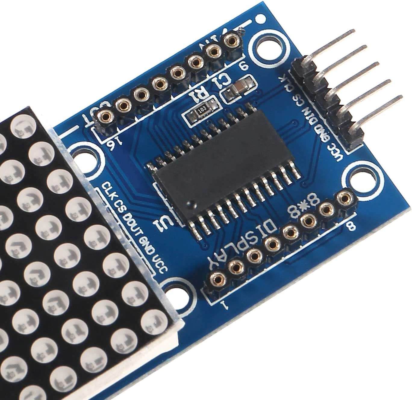
This is a tutorial on how to use the MAX7219 Dot Matrix LED Display With Arduino. We will use the LED matrix to display a scrolling message. this tutorial shows how to connect the display, how to install the MAX7219 Arduino library, and how to control it with Arduino.
Components Required
- LED Dot Matrix LED Display Module
- Arduino Board
- LED Matrix Display
- Jumper Wires
- Breadboard
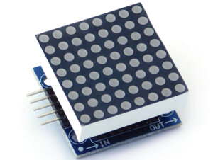
Dot Matrix LED Display
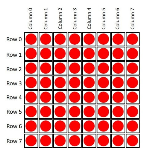
A Dot LED matrix display is a popular, affordable method of displaying graphic images or text Using LEDs. these LEDs are arranged in a grid matrix pattern and each led can be controlled individually. The matrix pattern is formed by rows and columns of LEDs, with each LED individually addressable.
A display’s resolution is determined by the number of pixels in the matrix, with higher resolutions allowing for more detailed and complex displays.
They are also available in different dimensions like 5 x 7, 8 x 8, 16 x 16, 32 x 32 etc. Based on the arrangement of the LEDs in the matrix, the LED matrix is a common row anode or common row cathode.
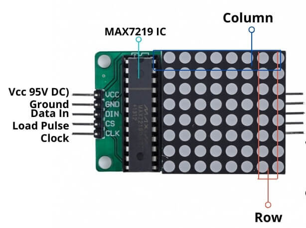
LED Dot Matrix Pinout
MAX7219 LED Driver
The MAX7219 LED driver IC (integrated circuit) is commonly used to control dot matrix LED displays. It allows for easy control of multiple LEDs at once and can be daisy-chained together to control larger displays.
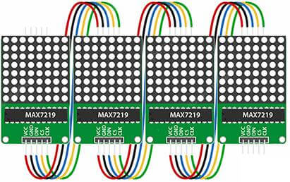
The MAX7219 is used to drive up to 64 individual LEDs, arranged in an 8×8 matrix pattern. It can be used to control multiple 8×8 Matrix daisy chains together. This allows for the output of larger displays with higher resolution.
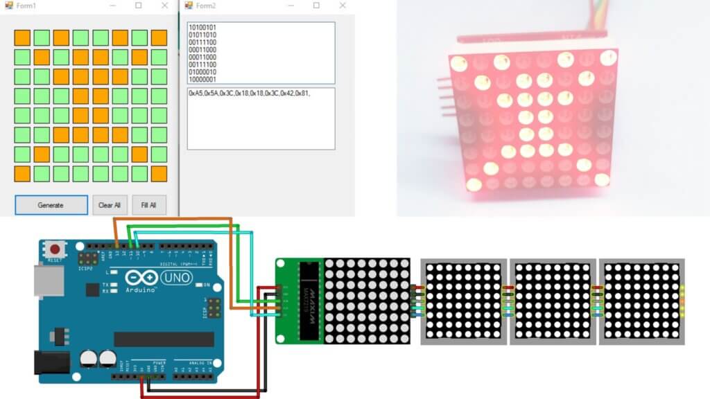
The 4 8×8 LED matrices are connected to each other via the MAX7219 pins.
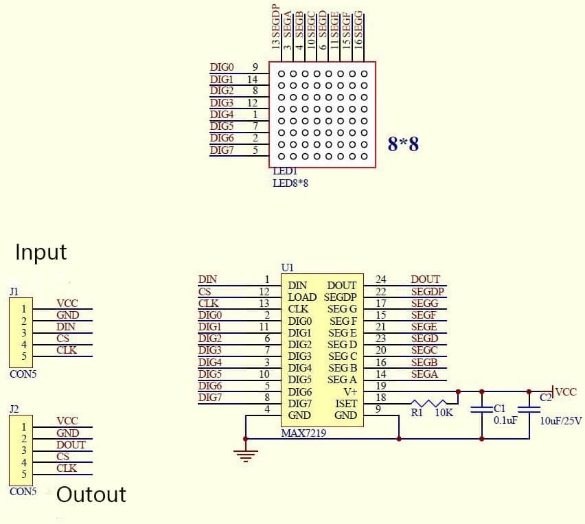
LED Matrix Display MAX7219 Schematic Diagram
8×8 MAX7219 Dot Matrix LED Display with Arduino
The connections are straightforward, and no soldering talents are needed.
- VCC pin of the MAX7219 to 5V on the Arduino
- GND pin of the MAX7219 to GND on the Arduino
- DIN pin of the MAX7219 to pin 11 on the Arduino
- CLK pin of the MAX7219 to pin 13 on the Arduino
- CS pin of the MAX7219 to pin 10 on the Arduino
Code & Libraries
Before you start coding, you need Arduino IDE. It is a powerful programming environment that enables you to create and program computer programs.
To control the dot matrix, you need to download and install it in your Arduino IDE the LedControl library. To install the library follow these steps:
- Download the latest version of the LedControl library.
- Unzip the .zip folder and you should get the LedControl-master folder.
-
Rename LedControl-master to LedControl
-
Move the LedControl folder to your Arduino installation libraries folder
Code
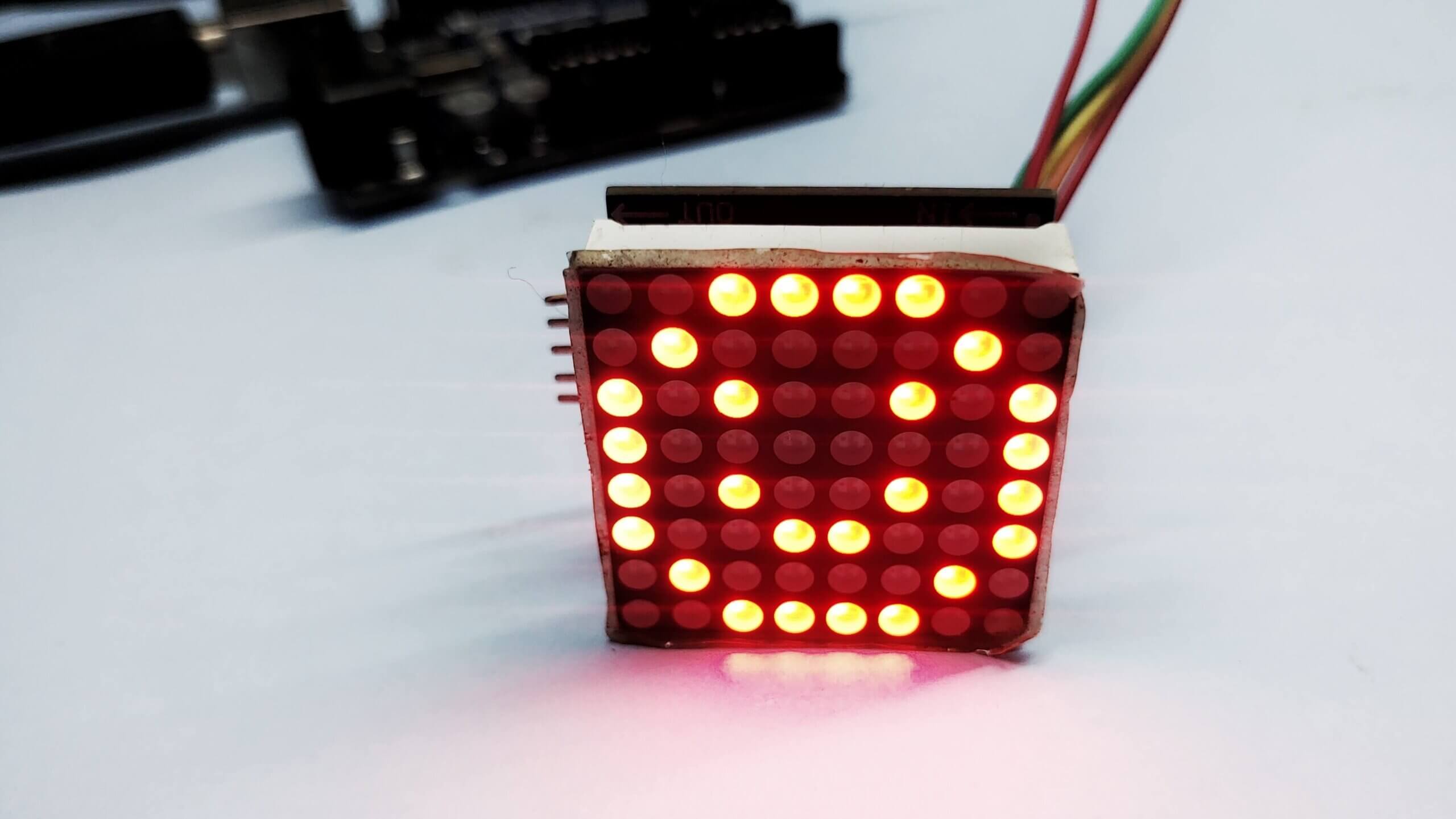
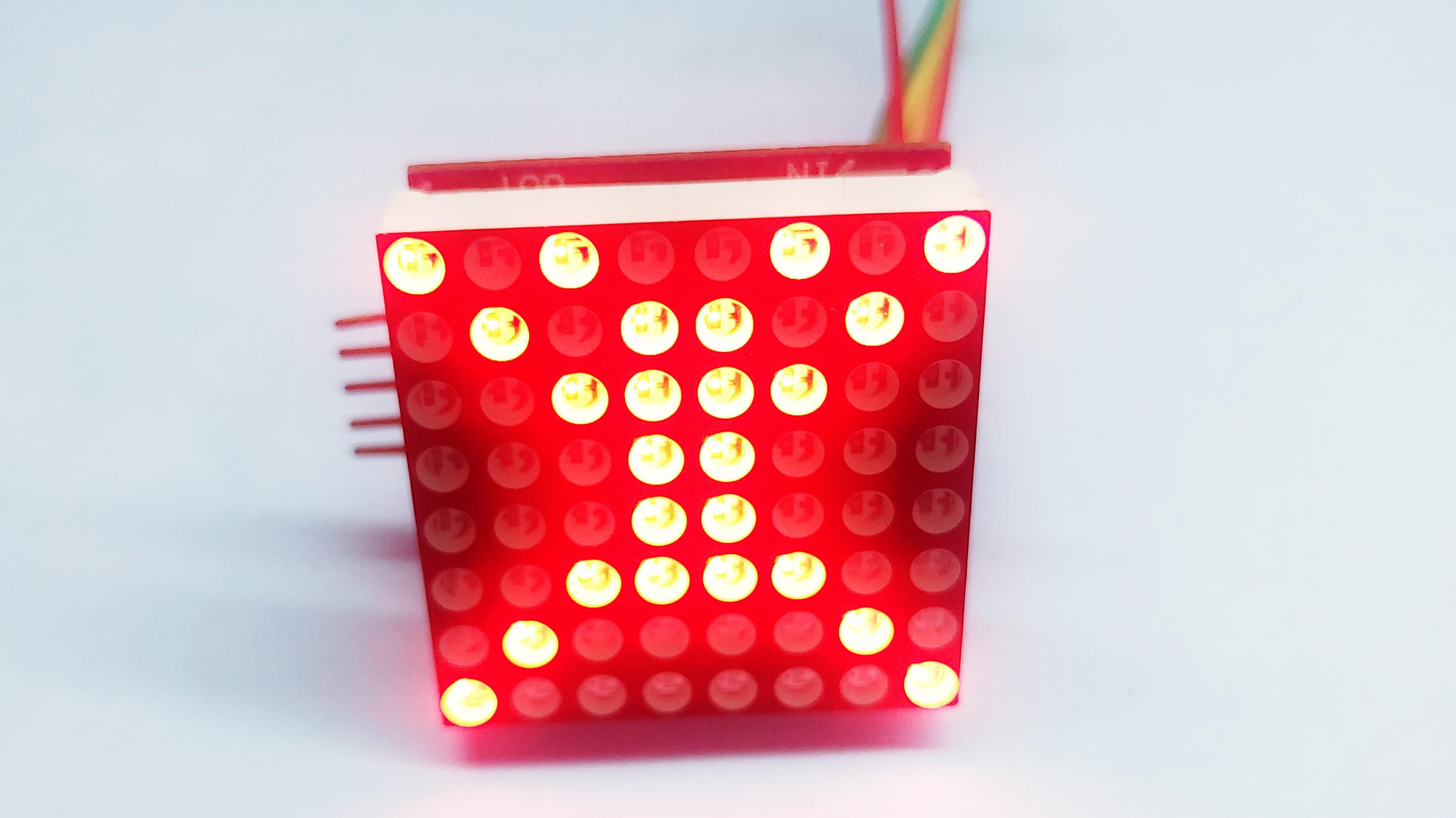
The code to generate a smiley on the LED matrix can be found here. The code is simple to understand and you can change the patterns of the LEDs in the code to generate a smiley on the LED matrix.
|
1 2 3 4 5 6 7 8 9 10 11 12 13 14 15 16 17 18 19 20 21 22 23 24 25 26 |
#include <LedControl.h> int DIN = 11; int CS = 10; int CLK = 13; LedControl lc=LedControl(DIN,CLK,CS,0); void setup(){ lc.shutdown(0,false); //The MAX72XX is in power-saving mode on startup lc.setIntensity(0,15); // Set the brightness to maximum value lc.clearDisplay(0); // and clear the display } void loop(){ byte a[8] = {0x3C,0x42,0xA5,0x81,0xA5,0x99,0x42,0x3C}; printByte(a); delay(1000); } void printByte(byte character []) { int i = 0; for(i=0;i<8;i++) { lc.setRow(0,i,character[i]); } } |
Outcome
Generate Pattern
Patterns can be generated using the Pixel to Matrix converter file. The converter file is attached below, you can download and use it to generate patterns.
The patterns are created by editing an array in the code to the required hex array, this hex array can be generated by downloading the converter and using the tool to generate hex strings.
When you’ve been done generating hex strings, you can copy and paste the string in the sample code from the previous step to create a custom pattern.
change the below line in the code
|
1 |
byte a[8] = {0xA5,0x5A,0x3C,0x18,0x18,0x3C,0x42,0x81}; |
Here is Result
The above steps should help you generate a pattern on an 8×8 matrix LED display using pixel-to-matrix mapping. You can modify the 2D array to create
Interfacing 8×32 MAX7219 Dot Matrix LED Display With Arduino
To drive an 8×32 MAX7219 Dot Matrix LED Display with Arduino, follow these steps:
Connect the LED display to your Arduino board using jumper wires. The connections are as follows:
- VCC pin of the MAX7219 to 5V on the Arduino
- GND pin of the MAX7219 to GND on the Arduino
- DIN pin of the MAX7219 to pin 11 on the Arduino
- CLK pin of the MAX7219 to pin 13 on the Arduino
- CS pin of the MAX7219 to pin 10 on the Arduino
Code & Libraries
The MAX7219 module is a universal LED display driver that can control LED Matrix and displays. However, controlling it directly can be quite challenging,
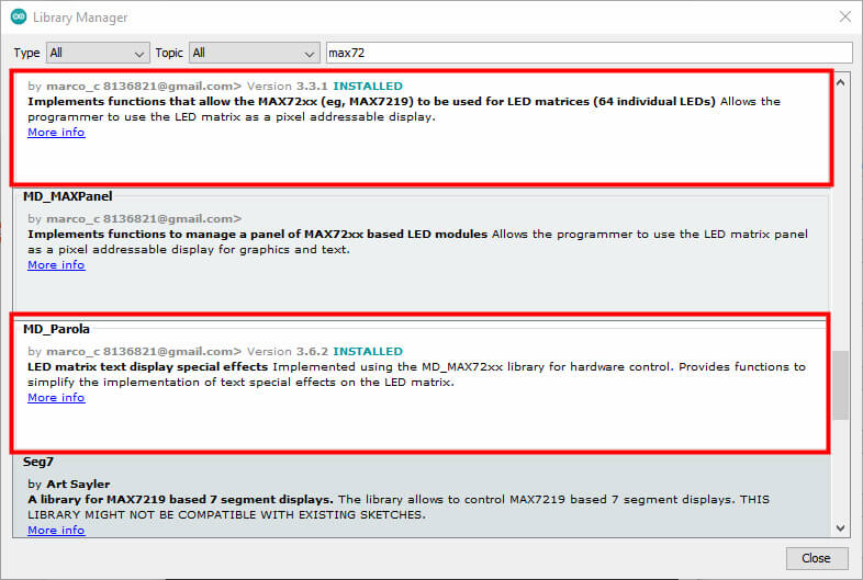
The MD_Parola library simplifies this process. with this library, you can easily control your LED matrix using simple commands and parameters. Md Parola library is built on the MD_MAX72XX library, which is a common library for controlling the MAX7219-based LED matrix and displays.
Source Code
|
1 2 3 4 5 6 7 8 9 10 11 12 13 14 15 16 17 18 19 20 21 22 23 24 25 26 27 28 29 30 31 32 33 34 35 |
/* Example code for scrolling text effect on MAX7219 LED dot matrix display with Arduino. more info https://diyprojectslab.com/*/ // Include the required Arduino libraries: #include <MD_Parola.h> #include <MD_MAX72xx.h> #include <SPI.h> // Define hardware type, size, and output pins: #define HARDWARE_TYPE MD_MAX72XX::FC16_HW #define MAX_DEVICES 4 #define CS_PIN 10 // Create a new instance of the MD_Parola class with hardware SPI connection: MD_Parola myDisplay = MD_Parola(HARDWARE_TYPE, CS_PIN, MAX_DEVICES); // Setup for software SPI: // #define DATAPIN 2 // #define CLK_PIN 4 // MD_Parola myDisplay = MD_Parola(HARDWARE_TYPE, DATA_PIN, CLK_PIN, CS_PIN, MAX_DEVICES); void setup() { // Intialize the object: myDisplay.begin(); // Set the intensity (brightness) of the display (0-15): myDisplay.setIntensity(0); // Clear the display: myDisplay.displayClear(); myDisplay.displayText("DiY Projects Lab", PA_CENTER, 100, 0, PA_SCROLL_LEFT, PA_SCROLL_LEFT); } void loop() { if (myDisplay.displayAnimate()) { myDisplay.displayReset(); } } |
Testing

