Introduction
In this tutorial, we will show you how to use the MCP2515 SPI CAN Bus Module With Arduino. MCP2515 CAN bus controller is a stand-alone CAN controller that implements the CAN protocol. The CAN bus is a message-based protocol that allows devices to communicate with each other.
Controller Area Network also known as CAN-BUS is an industrial bus with long travel distance, medium communication speed, and high reliability. It is right for modern machine tools and automotive diagnostic bus uses which are used by a wide collection.
It is generally found on present machine devices and as an automotive bus. Multiple developments have been manufactured that share to be available for CAN Communication.
Required Material
What is CAN BUS (Controller Area Network)?
CAN or controller area network is a kind of communication network between a microcontroller and devices in a vehicle. It is also known as a CAN bus because a shared bus is attached to all the devices of the vehicle. CAN bus protocol is a message-based protocol, which means that each message has a specific format.
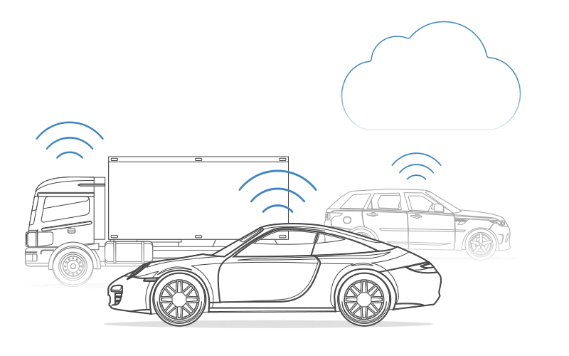
CAN-BUS is a data communications system that was originally designed for the automotive industry. It is a two-wire bus that uses differential signaling to send data between ECUs. CAN-BUS is a data communications was originally designed for the automotive industry. Its primary aim is to allow electronic control units (ECUs) to communicate with electronic control units, or ECUs, in cars and trucks.
For example, a control unit is a central module used in cars. One of these is the engine control unit, which is connected to numerous sensors and actuators like airbags, antilock braking, electric power steering, audio systems, control windows, doors, mirror adjustment, battery, motors for air control, etc.
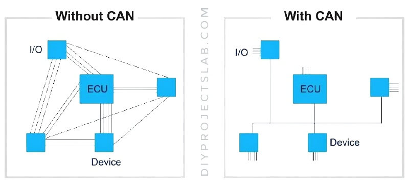
Example of CAN and Without CAN BUS Communication.
CAN-BUS is used in vehicles to reduce wiring harnesses and to allow for the diagnostics of components on the network.
CAN bus is the Data Transmission cable between devices in an industrial environment. It is popular for its high speed and powerful network. It is very reliable in tough conditions. The CANbus cable has two wires ( CAN high and CAN low) which are twisted together to make the main bus.
Each network node holds a unique identifier. it means the main bus is linked with all the devices. The cable is attached to one device which transfers the data to another device and so on. Imagine there are three devices(A, B, and C) linked to the microcontroller via the main bus.
If the microcontroller wants to transmit data to device C then first the data goes to device A. Device A matches the data and see that it is for device C so it redirects it to device B, then device B also checks that it is for device C so it finally redirects data to device C.
The voltage difference between CAN high wire and CAN low wire makes different electrical signals to the devices (ECUs).
The high voltage on a CAN bus is 3.75 volts, while the low voltage is 1.25 volts. When these voltages are added together, you get 5 volts.
- CAN high holds voltage between 2.5V to 3.5V.
- CAN low hold voltage between 2.5V to 1.5V.
The data transfer speed of CAN goes up to 1Mbps.
Applications of CAN BUS
The CAN bus is used in a variety of applications, including automotive, industrial, medical, and aerospace.
- Transportation systems
- Automation in buildings
- Used in elevators
- Used in ships
- Lighting control systems
- Agricultural equipment
- Industrial automation
- Used in medical instruments
Comparison of CAN over I2C & SPI
| I2C | SPI | CAN | |
| Speed | Standard: 100Kbps, Fast: 400 Kbps, Highspeed:3.4Mbps | 3Mbps to 10Mbps | 10KBps to 1MBps |
| Types | Synchronous | Synchronous | Asynchronous |
| Wires | 2 wires (SDA, SCL) | 4 Wires (MISO, MOSI, SCK, CS) | 2 wires (CAN_H, CAN_L) |
| Duplex Mode | Half Duplex | Full Duplex | Half Duplex |
What is an MCP2515 SPI CAN Bus Module
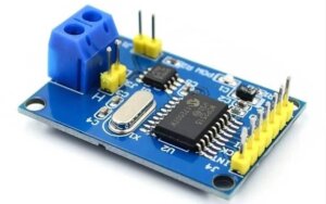
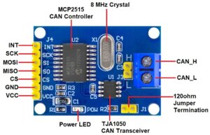
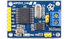
The MCP2515 CAN Bus Module is a simple module that supports CAN Protocol version 2.0B and can be used for communication at 1Mbps. The controller is a single chip and can be inserted into any Next environment. It can also be interfaced with Arduino and Raspberry PI Board.
This special module is based on MCP2515 CAN Controller IC and TJA1050 CAN Transceiver IC which is a high-speed CAN trans-receiver. This module communicates with the microcontroller over the SPI interface and works from 2.7 to 5.5V. The MCP2515 IC is a standalone CAN Controller.
This breakout board has an 8 MHz Crystal oscillator and even a 16 MHz version. A jumper can be attached which will give 120ohm Termination. CAN_H & CAN_L are the two screws where wires can be attached over length for transmitting with other CAN Module
MCP2515 CAN Module Schematic Diagram
The schematic of the MCP2515 CAN Module is below. This module is capable of allowing numerous devices to be connected to it, allowing them to communicate data and power.
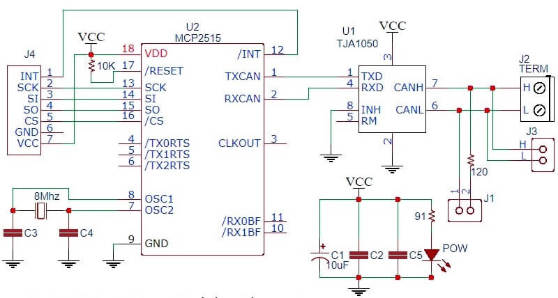
The MCP2515 IC is the main controller that internally consists of three main subcomponents: The CAN Module, the Control Logic, and the SPI Block. The CAN Module is responsible for sending and receiving messages on the CAN Bus.
The Control Logic handles the setup and operation of the MCP2515 by interfacing all the blocks. The SPI Block is responsible for the SPI communication interface. The TJA1050 IC IC is responsible for outputting the data from the controller and relaying it onto the bus.
MCP2515 CAN Bus Module Pinout
Pinout of MCP2515 CAN Bus Module:-
- INT: This is the interrupt pin. It can be used to generate an interrupt.
- SCK: This is the clock pin. It is used to provide the clock signal for the SPI bus.
- SI: This is the serial input pin. It is used to input data to the MCP2515 over the SPI bus.
- SO: This is the serial output pin. It is used to output data from the MCP2515 over the SPI bus.
- CS: This is the chip select pin. It is used for communication over the SPI bus.
- VCC: This is the power supply pin.
- GND: This is the ground pin.
Specifications & Features of MCP2515 CAN Bus Module
- Support CAN V2.0B
- Communication rate 1Mb/S.
- Use High-speed CAN transceiver TJA1050
- SPI control for expanding Multi CAN bus interface
- 8MHZ crystal oscillator
- 120Ω terminal resistance
- Module 5V DC power supply.
- Dimension: 40×28mm
- 0 to 8 bytes long data field.
- Up to 112 nodes can be connected
- It Has a separate key, LED indicator, and Power indicator
- Working current: 5mA (1 microamp standby current).
- Operating temperature: -40 C – +85 C
For more information, you can refer to the MCP2515 Datasheet which also has a detailed guide
How does the MCP2515 Module work with Arduino?
To use the MCP2515 Module with an Arduino, you will need to connect the module to Arduino using the SPI interface. It is commonly used to provide an interface between a microcontroller and external hardware, such as sensors and actuators. you can use the MCP2515 library to transmit and receive data over the CAN bus.
You can use an Arduino board to complete tasks such as sending messages, receiving messages, and monitoring the condition of the CAN bus.
Interfacing MCP2515 SPI CAN Bus Module With Arduino
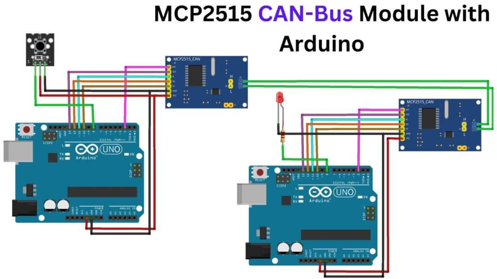
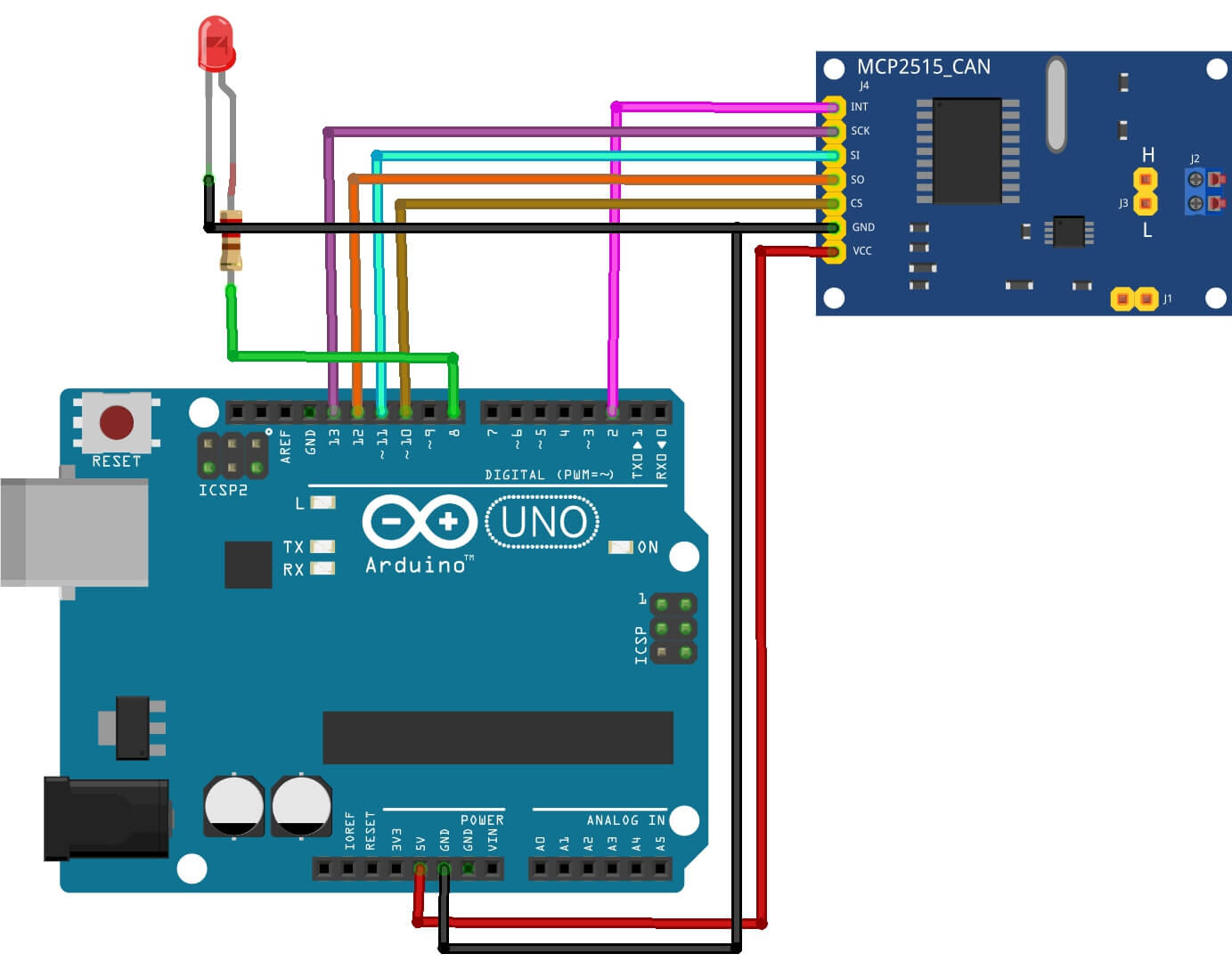
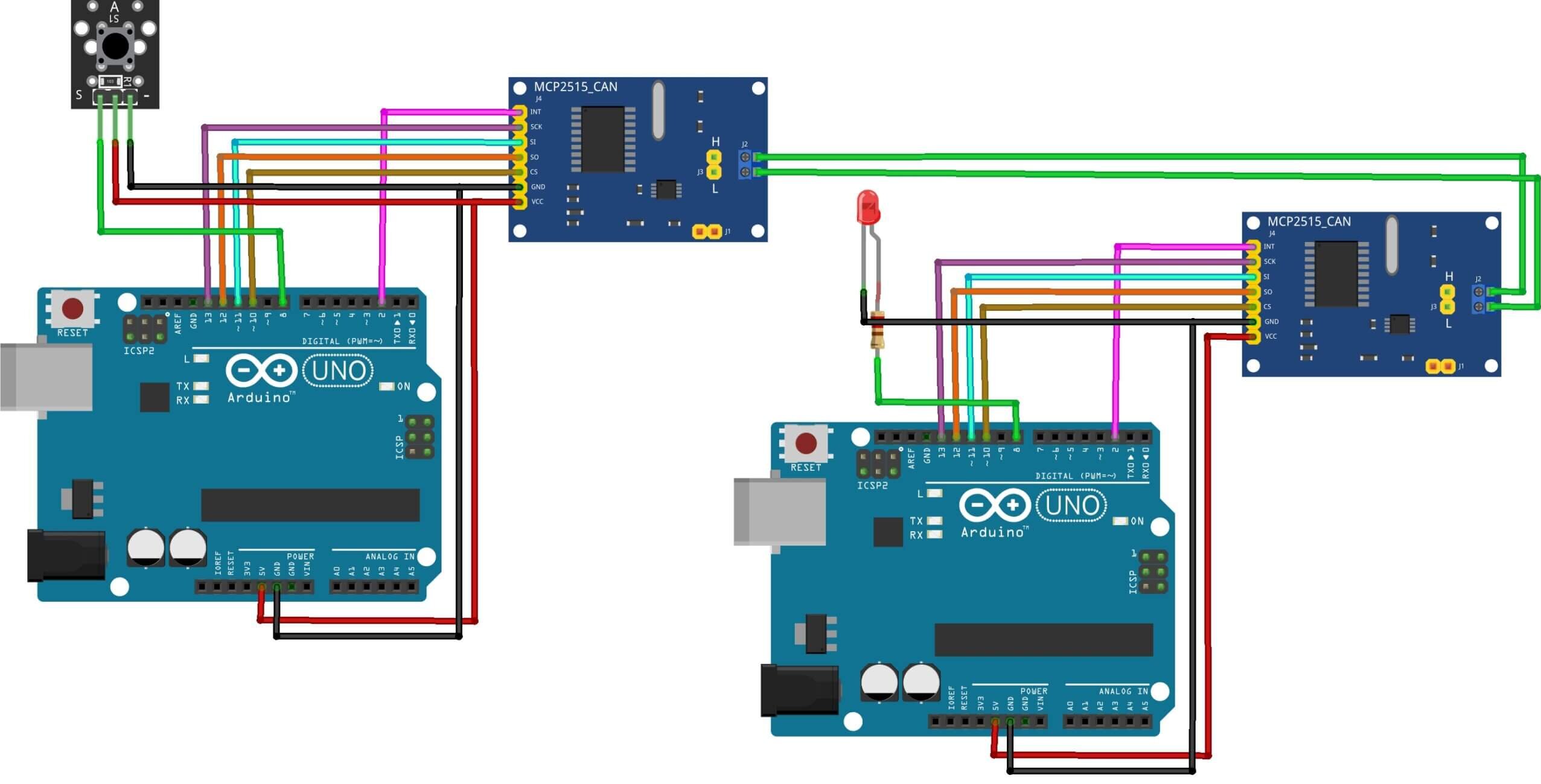
In this example, we will read the status of an input and send the provided value to another Arduino, which will check the current condition of the input and turn an LED on or off depending on the reading.
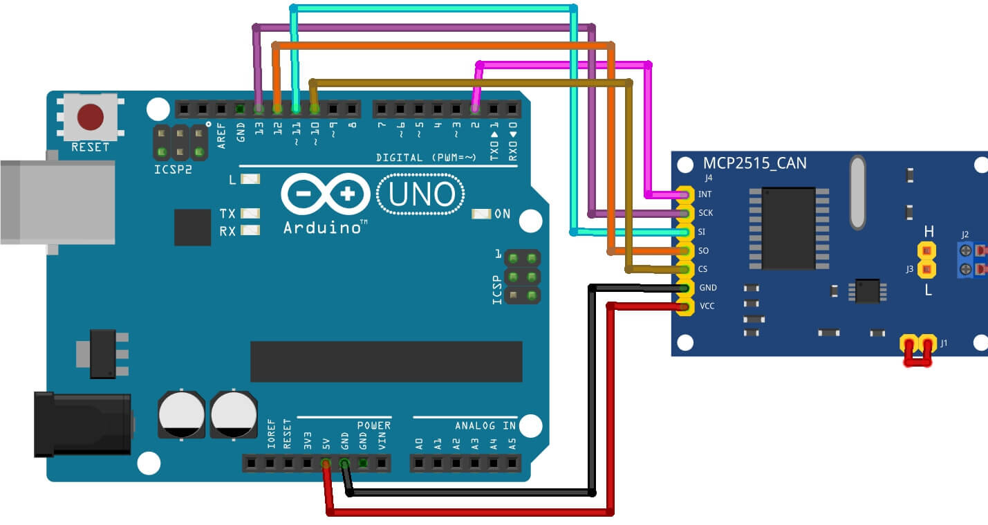
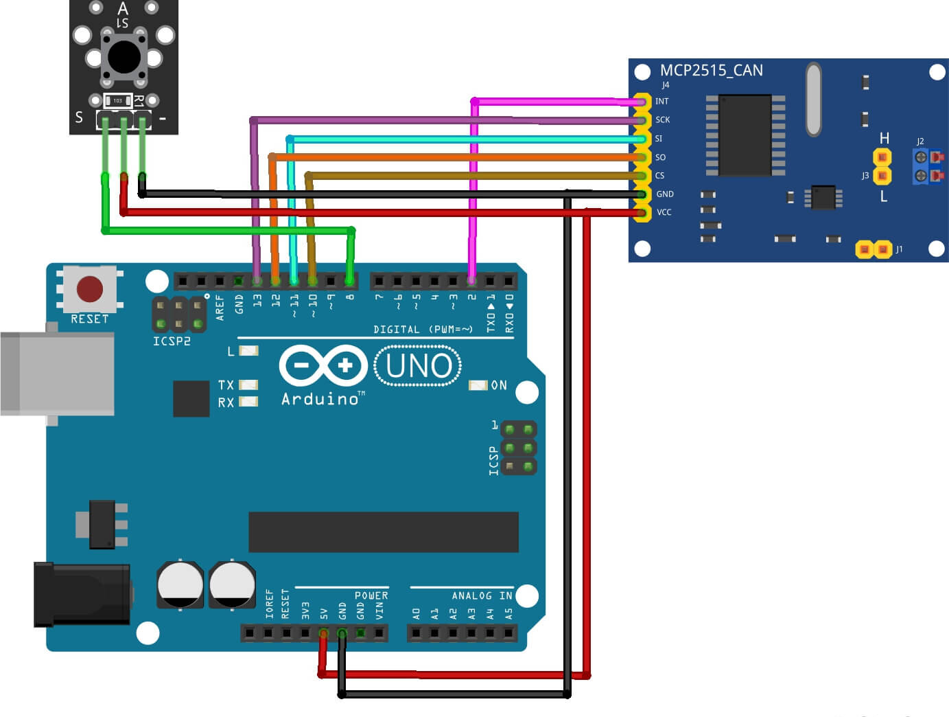
| MCP2515 Pin | Arduino Pin |
| VCC | 5V |
| GND | GND |
| CS | D10 |
| SO | D12 |
| SI | D11 |
| SCK | D13 |
| INT | D2 |
Receiver Circuit Diagram
A receiver circuit diagram for an MCP2515-based design below shows the connections between the MCP2515, the CAN transceiver, with Arduino microcontroller, and the other components in the system.
Receiver Code
Before starting on the coding part of the project, we need to install MCP2515 CAN Bus Library to the Arduino IDE. Download the library from the following link and then add it to the Arduino Library folder. download the code & circuit diagram from GitHub.
|
1 2 3 4 5 6 7 8 9 10 11 12 13 14 15 16 17 18 19 20 21 22 23 24 25 |
#include <SPI.h> #include <mcp2515.h> #define led 8 struct can_frame canMsg; MCP2515 mcp2515(10); void setup() { mcp2515.reset(); mcp2515.setBitrate(CAN_125KBPS); mcp2515.setNormalMode(); pinMode(led, OUTPUT); } void loop() { if (mcp2515.readMessage(&canMsg) == MCP2515::ERROR_OK) { if(canMsg.data[0]){ digitalWrite(led,HIGH); } else{ digitalWrite(led,LOW); } } } |
Transmitter Circuit Diagram
Transmitter Code
|
1 2 3 4 5 6 7 8 9 10 11 12 13 14 15 16 17 18 19 20 21 22 23 24 25 26 27 28 29 30 31 32 33 34 35 36 37 38 39 40 |
#include <SPI.h> #include <mcp2515.h> #define btn 8 struct can_frame canMsg1; MCP2515 mcp2515(10); bool state = 0; void setup() { canMsg1.can_id = 0x01; canMsg1.can_dlc = 1; canMsg1.data[0] = 0x00; mcp2515.reset(); mcp2515.setBitrate(CAN_125KBPS); mcp2515.setNormalMode(); pinMode(btn, INPUT_PULLUP); } void loop() { if (!digitalRead(btn)) { //antirebote while (!digitalRead(btn)) { delay(10); } state = !state; if (state) { canMsg1.data[0] = 0x01; } else { canMsg1.data[0] = 0x00; } mcp2515.sendMessage(&canMsg1); } } |
MCP2515 With Arduino Using CAN Bus Communication
The transmitter and receiver Parts are connected to the CAN Bus Module (MCP2515) by their CAN-H and CAN-L pins. The following image shows you communication between two Arduino over CAN Protocol.
Conclusion
After making the, upload the program for the CAN transmitter and CAN receiver in the individual Arduino boards. When pushing the switch button you should notice the LED will be On in another Arduino through CAN communication.
The MCP2515 CAN Bus Module allows the Arduino to communicate with other devices on a CAN bus. It is easy to use with Arduino. By following the steps in this tutorial, you can easily get your Arduino. check out How To Connect Arduino To Raspberry Pi With Serial Communication

