In this tutorial, we’ll show you how to measure AC current using Arduino and SCT-013 current transformers. this guide goes over how to use the SCT-013 current sensor with Arduino. This sensor is used to measure alternating current (AC) up to 100 amps. We’ll go over how to wire the sensor, how to get readings from the sensor, and how to calculate the current drawn from the sensor.
The SCT-013 current transformer is common in home energy meters. It is a component that measures the current in a wire without having to break the circuit.
Required Material
To measure AC current with Arduino, you will need the following components
- SCT-013 current sensor
- Arduino board
- Breadboard
- Jumper wires
- Load (for testing)
How does it work?
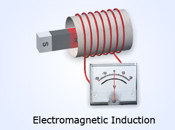
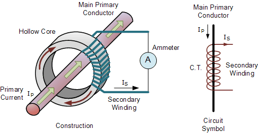
The SCT-013 current sensor operates on the principle of magnetic induction, which means that it can measure the current flowing through a wire without making physical contact with the wire itself.
It works based on the principle of magnetic induction, where a ferromagnetic core is used to detect the magnetic field generated by the current-carrying wire.
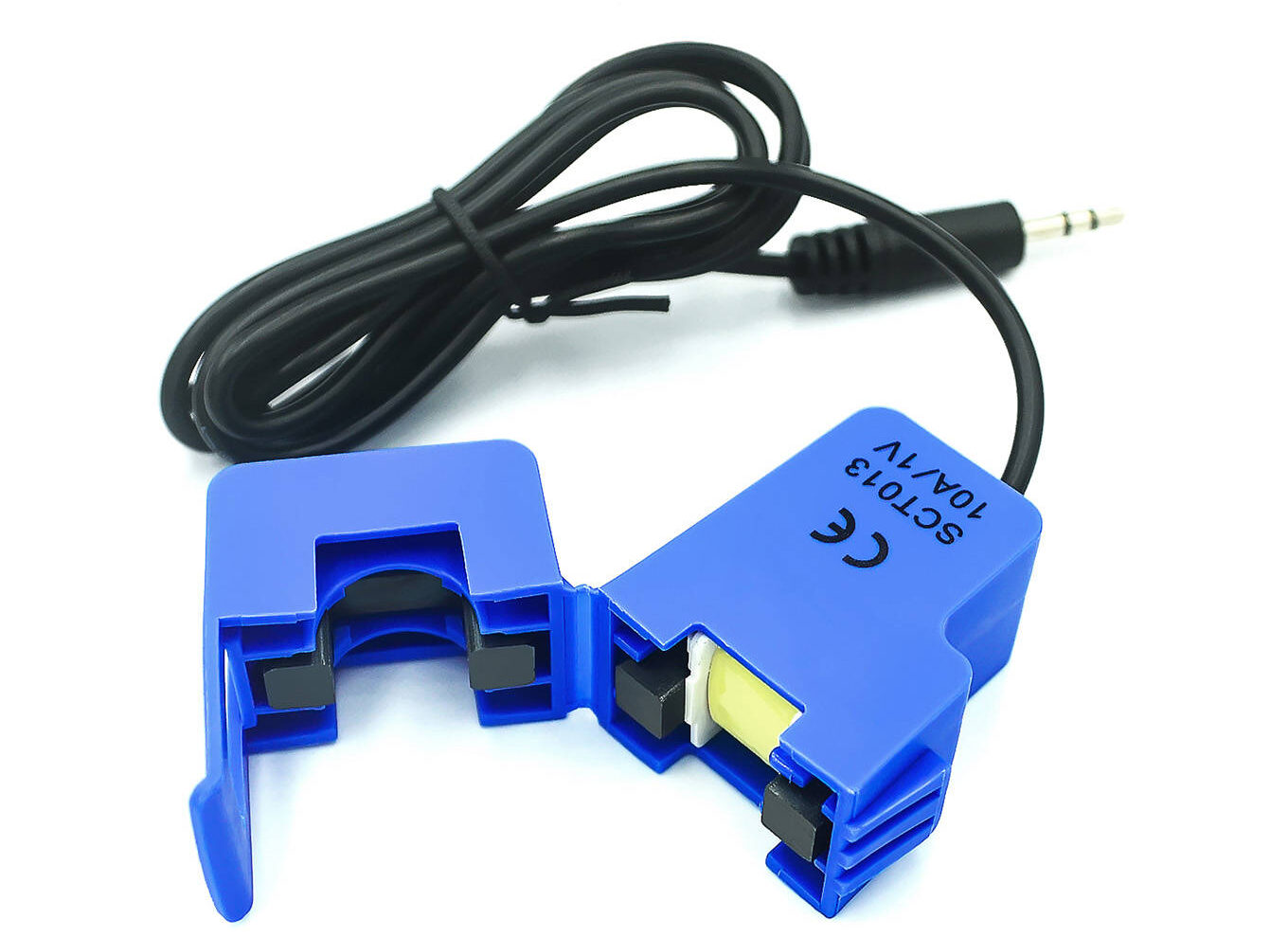
SCT-013 current sensor
The SCT013 sensors are instruments that help us measure the amount of electrical current flowing through a wire. without cutting or changing the wire. These sensors work by using a special technique called electromagnetic induction.
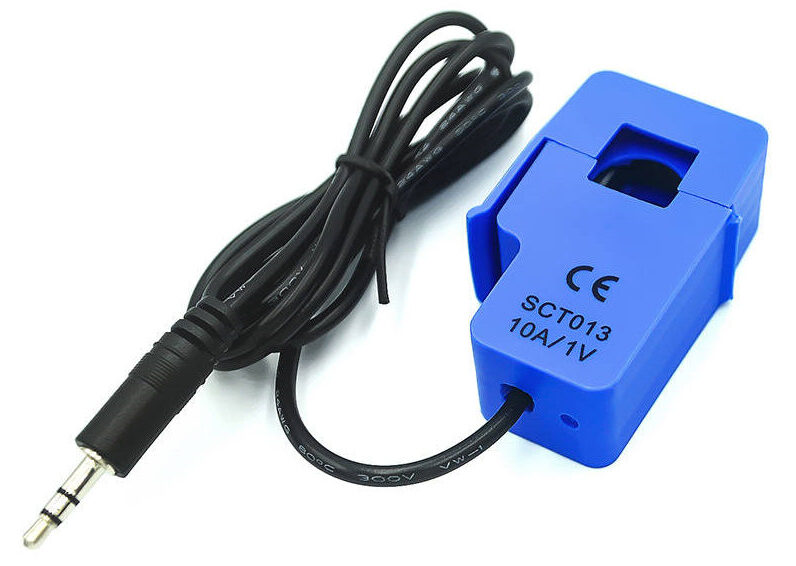
This makes it safe and easy to use, even for people who are not experienced with electronics. You can simply clamp it on and connect it to get the readings. The sensor can be connected to an Arduino or any microcontroller board to read the current values and use them for different purposes, such as monitoring power consumption or controlling a device based on current levels.
The SCT-013 is a convenient device that can be easily attached to either the live or neutral wire without any electrical work involving high voltage.
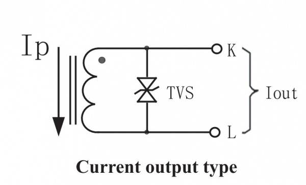
The sensor has a primary winding, a magnetic core, and a secondary winding. These are all composed of many Turns of fine Wire enclosed in the transformer casing.
SCT-013 current sensor Schematic
SCT-013 current sensor specs
Here are some specifications for the SCT-013 current sensor:
- Input Current Range: 0-30A AC
- Turns Ratio: 1800:1
- Non-linearity: <±3%
- Phase Shift: <±1°
- Operating Temperature: -25°C to +70°C
- Output Signal: AC voltage proportional to the input current
- Output Voltage at Rated Input Current: 1V (other values available depending on the model)
- Output connector: 3.5mm audio jack or 3-pin header
- Frequency Range: 50Hz – 60Hz
- Dielectric Strength: 6000V AC/1min
- Accuracy: Class 1 (IEC 61869)
- Dimensions: 50mm x 34mm x 25mm
Note – These specifications may differ on the manufacturer and model of the SCT-013 current sensor, so it is always important to refer to the datasheet for the specific specifications.
SCT-013 Current Sensor Application
- Energy monitoring:
- Power management
- Renewable energy systems
- Industrial automation
The SCT-013 current sensor is relatively simple to use and can be a helpful tool for hobbyists, students, or professionals working in fields related to electronics or electrical engineering.
SCT-013 current sensor Wiring
16×2 LCD Display
16×2 LCD (Liquid Crystal Display), is a type of display used in electronics to display numbers, letters, and in some cases, symbols. The screen is arranged into a 16×2 grid, each grid representing a pixel.
The display is built up of two rows containing sixteen characters each, hence the name “16×2“. Each character is made up of five by eight pixels, which can be used to display letters, numbers, and/or symbols. check the previous post How to use 16×2 LCD With Arduino – Tutorial
Interfacing Current Sensor SCT-013 And Arduino
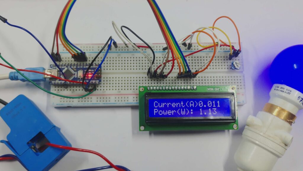
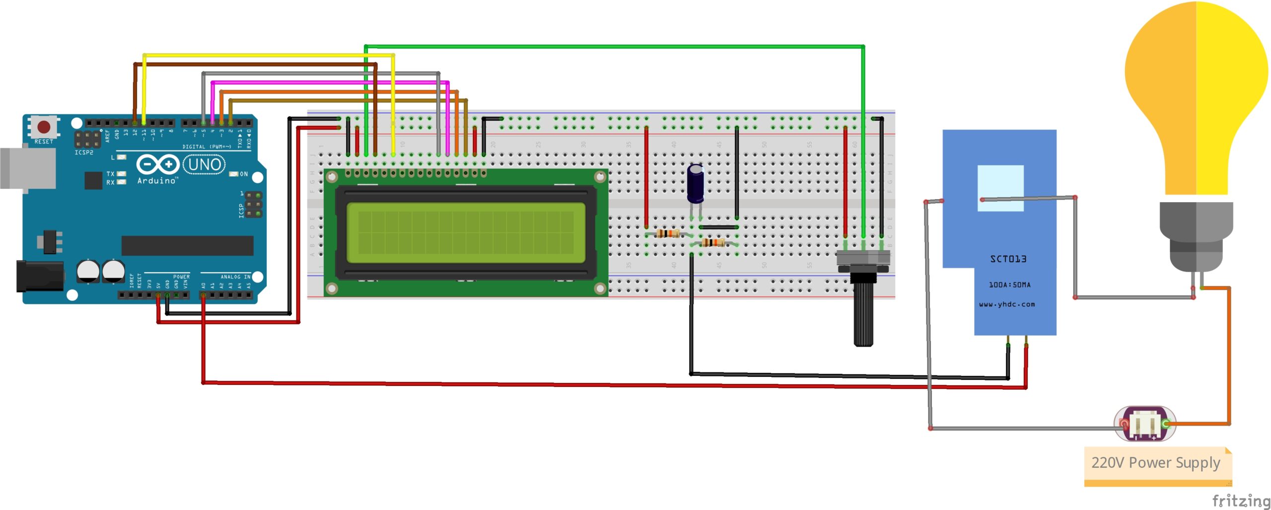
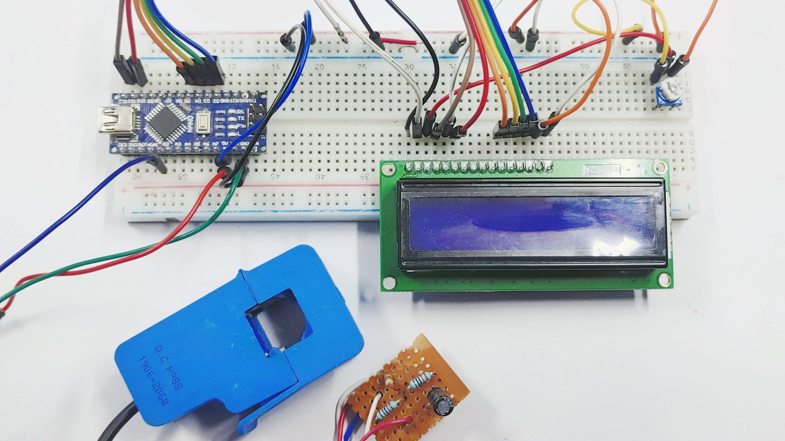
The Electricity Energy Meter using Arduino is a simple circuit diagram shown below.
The following connections are required:
- SCT sensor output pin to analog input pin A0 of the Arduino.
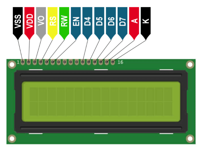
- LCD pins RS, E, D4, D5, D6, and D7 to digital pins 12, 11, 5, 4, 3, and 2 of the Arduino, respectively.
- LCD VSS pin to ground (GND) of the Arduino.
- LCD VDD pin to +5V pin of the Arduino.
- LCD V0 pin to a potentiometer, with the pins of the potentiometer connected to +5V and GND of the Arduino.
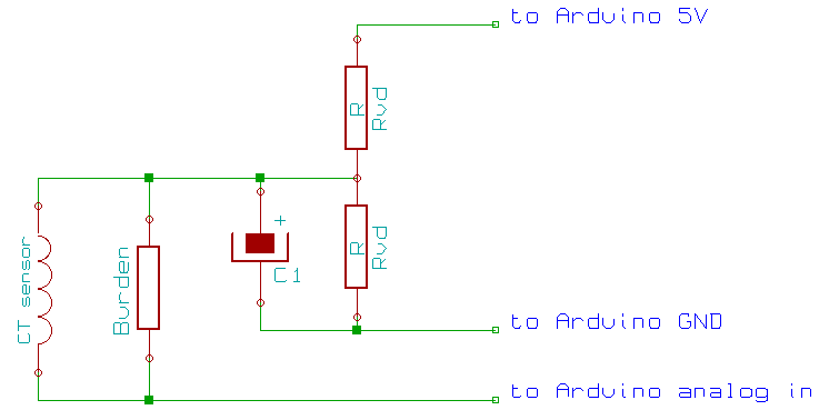
A 10K resistor and a 100-ohm resistor are required to complete the circuit. In addition, a 10uF capacitor is required.
How to calculate current drawn by an electrical device
To calculate the current drawn by the electrical device from the power supply, we can use the simplified formula:
I = P / E
Where I is the current in amperes (A), P is the power in watts (W), and E is the voltage in volts (V).
For example, if a device has a power rating of 2200 W and is attached to a power supply of 220 V, the current drawn would be 10 A (amperes), which can be calculated as follows:
I = P / E = 2200 W / 220 V = 10 A
The program we created was based on the resources and instructions provided by the Open Energy Monitor website, specifically the EmonLib library made for this type of sensor.
The library can be downloaded from the above link and should then be unzipped and put in the Libraries folder of the Arduino IDE.
Source code
|
1 2 3 4 5 6 7 8 9 10 11 12 13 14 15 16 17 18 19 20 21 22 23 24 25 26 27 28 29 30 31 32 33 34 35 36 37 38 39 40 41 42 43 44 45 |
#include <EmonLib.h> #include <LiquidCrystal.h> EnergyMonitor emon1; LiquidCrystal lcd(12, 11, 5, 4, 3, 2); // Voltage of the electric int voltage = 230; // Pin of the SCT sensor int sct_pin = A0; void setup() { lcd.begin(16, 2); lcd.clear(); Serial.begin(9600); // Pin, calibration - Current Constant = Ratio/BurdenR. 1800/62 = 29. emon1.current(sct_pin, 29); // Initial display information lcd.setCursor(0,0); lcd.print("Current(A): "); lcd.setCursor(0,1); lcd.print("Power(W): "); } void loop() { // Calculate the current double Irms = emon1.calcIrms(1480); // Show the current value Serial.print("Current: "); Serial.print(Irms, 2); // Irms lcd.setCursor(10,0); lcd.print(Irms, 2); // Calculate and show the power value double power = Irms*voltage; Serial.print(" Power: "); Serial.print(power, 2); lcd.setCursor(10,1); lcd.print(" "); lcd.setCursor(10,1); lcd.print(power, 2); delay(1000); } |
To modify the voltage, adjust the variable “voltage” in the code. To use a different analog input on another Arduino board, update the variable “sct_pin” accordingly.
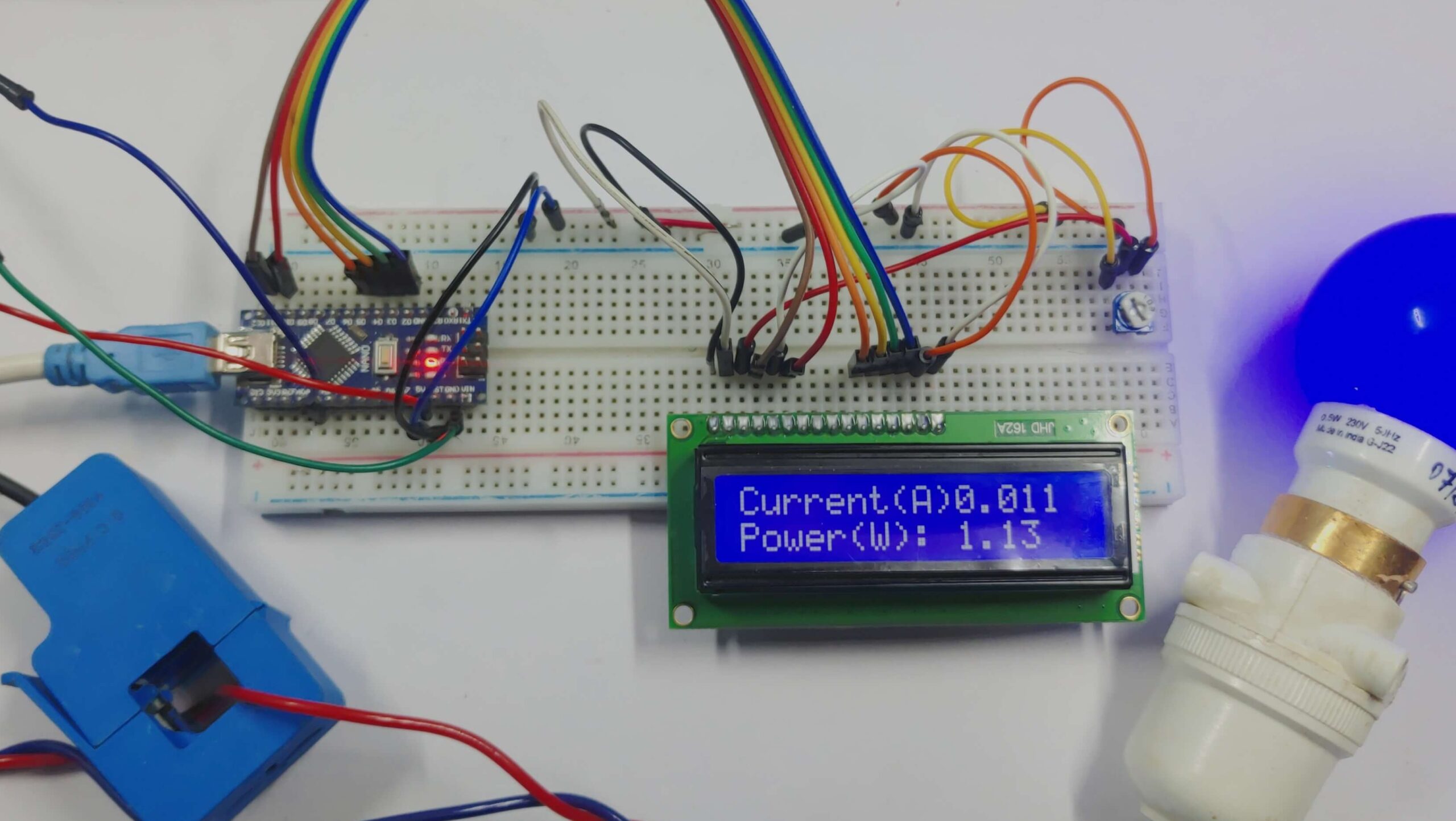
Working
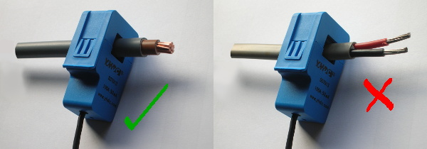
When taking measurements with the sensor, it is important to only apply ONE of the wires as shown in the below image.
If both wires are put inside the sensor, the values will cancel, resulting in a reading of 0 or an incorrect value on the display.

14 Comments
If I use SCT-013-30A module than what will be the change in sketch
If you change to the SCT-013-30A module, make sure to adjust the calibration value in the code according to the specifications of this new sensor to get accurate current measurements.
Hi!
In line “double Irms = emon1.calcIrms(1480);”, where does the 1480 value come from?
Thank you.
The value 1480 in emon1.calcIrms(1480) represents the number of samples taken to accurately calculate the Root Mean Square (RMS) current. Adjusting this value can impact the accuracy.
Hello, i am interest, if can more to 150A? thank you
HI!
I am interest. If can more CT 150A?
thank you
Well ,, theoretically you can measure more than the rated current but there would be inaccuracies in the measurement due to the transformer saturating, and you also need to change the bias resistors to step down voltage so as to not go beyond the max voltage rating of the transformer
Hi, about SCT 013, there are three wires, which are white, black and red. do you know their terminals and how to connect it?
Connect white to tip, black to sleeve, and note red is unused in SCT-013-030. For SCT-013-000, red acts as a burden resistor.
So according to your schematic diagram, i am only using red and black wire right? so the white wire i am not using it
Yes, the sensor is actually a transformer secondary and hence has only 2 pins, its cause we use 3.5mm jack we have 3 pins
What’s the purpose of potentiometer?
The potentiometeris used to controls the contrast between the characters(or graphics) and background color of LCD.
In my own case I can only see red and white wires