Introduction
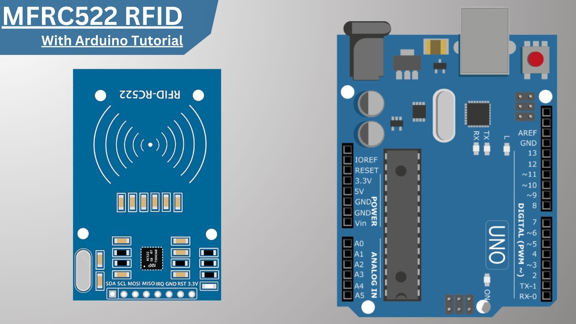
In this RFID sensor with Arduino tutorial, we are going to be using the MFRC522 RFID Module With Arduino. The RFID RC522 is a very low-cost RFID sensor that is popular with hobbyists and makers. This sensor can be used to read and write RFID tags. The tutorial includes a list of materials needed and step-by-step instructions for wiring the RFID module to the Arduino and programming it.
The RFID reader reads the identification number of the RFID tag. The identification number is then sent to the Arduino board. The Arduino board uses the identification number to do an action, such as turning on a light or opening a door.
Required Material – RFID Module With Arduino
- Arduino UNO (Amazon.Com)
- RC522 RFID Sensor Module (Amazon.Com)
- Light-Emitting Diode (LED) (Ammzon.Com)
- Breadboard (Amazon.Com)
- Jumper Wire (Amazon.Com)
What is RFID?
RFID (radio frequency identification) is a type of wireless technology that uses radio waves to communicate with a tag placed on an object. The tag contains information about the object, such as a serial number, and an RFID reader can read the tag.
This allows for much faster scanning of large numbers of objects. RFID is used in many applications, including access control, asset tracking, and inventory management.
RFID Tags
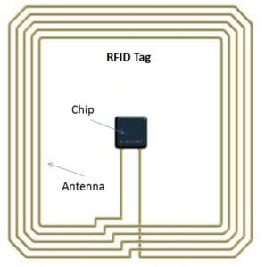
RFID or “radio-frequency identification,” tags have an internal antenna and an integrated circuit that is responsible for communicating with the reader device. an antenna is simply a coil of wires and it normally occupies an important portion of the tag’s internal space. T
The purpose of the antenna is to create communication with the reader and also to obtain enough energy from the received waves to power the internal circuits.
How does RFID work?
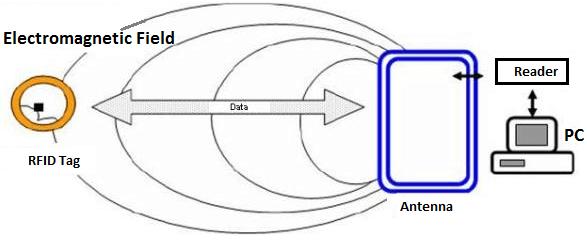
RFID is a system that uses electromagnetic fields to automatically identify and track tags attached to objects. The tags contain electronically stored information.
Passive tags collect energy from a nearby RFID reader’s interrogating radio waves. Active tags have a local power source, such as a battery, and may operate hundreds of meters from the RFID reader.
Unlike a barcode, the tag need not be within the line of sight of the reader, so it may be embedded in the tracked object.
MFRC522 RFID Module
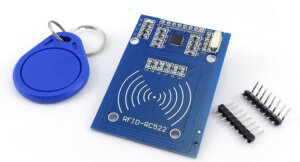
An MFRC522 RFID sensor is a device that can be used to read and write data to an RFID tag. RFID tags are used in a variety of applications, such as tracking inventory, identifying people or animals, and security. The MFRC522 is a highly integrated reader/writer IC for contactless communication at 13.56MHz.
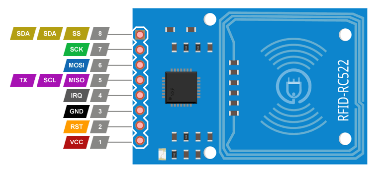
MFRC522 RFID Module Pinout
The pinout of the MFRC522 RFID module is shown below.
Connecting the RFID Module With Arduino
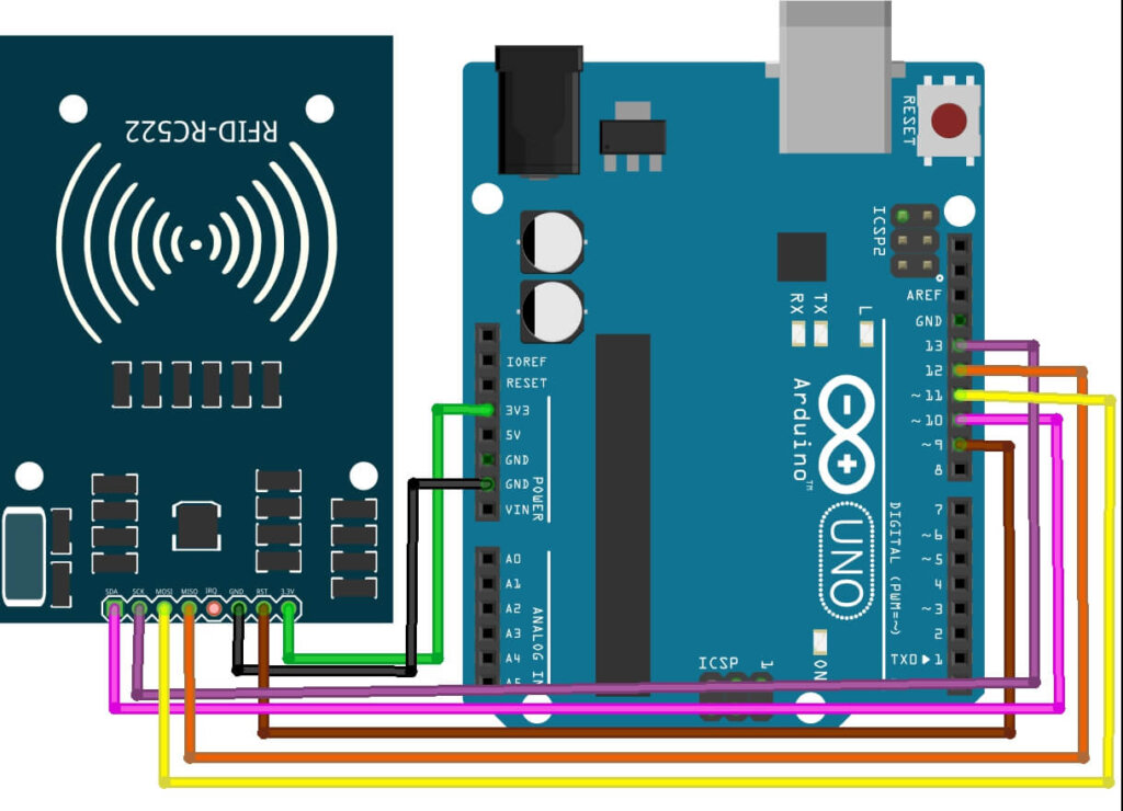
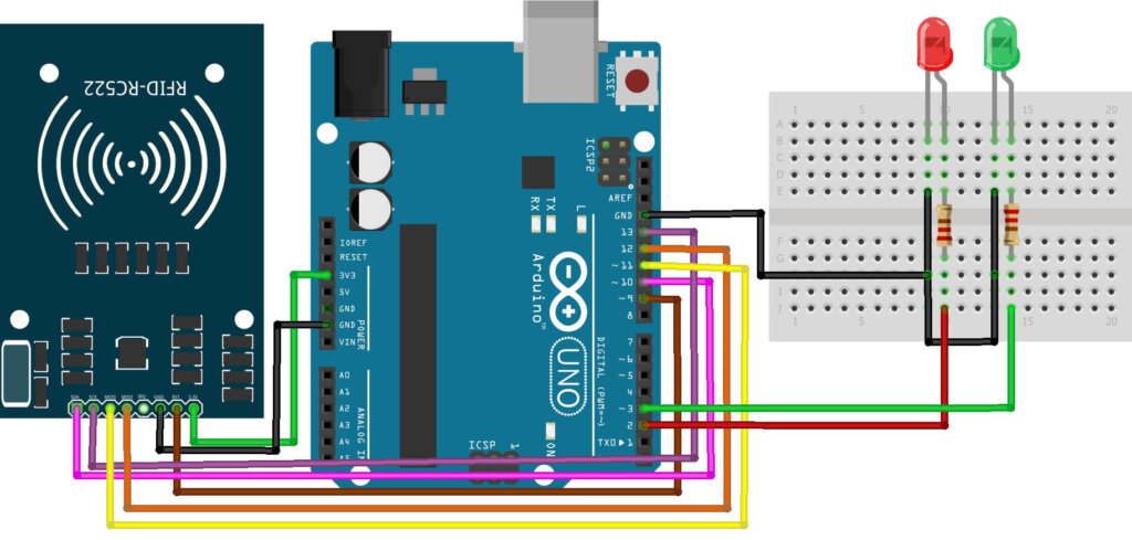
The RFID RC522 module uses the SPI interface to make bi-communicative contact with the Arduino through digital pins 10 to 13, with pin 9 connected to the module’s RST. Inspect the arrangement of the pins in the interface shown below, showing the arrangement of the module connection pins to the Arduino, which are supported by the MFRC522 library.
| MFRC522 module | Arduino Uno, Nano | |
|---|---|---|
| SDA (SS) | 10 | |
| SCK | 13 | |
| MOSI | 11 | |
| MISO | 12 | |
| IRQ | Not connected | |
| GND | GND | |
| RST | 9 | |
| 3.3V | 3.3V |
Note – the module power supply, is done through the 3.3V pin of the Arduino.
MFRC522 Programming & Code :
Here’s the library you need for this project:
- Download the RFID library here developed by Miguel Balboa.
- Unzip the RFID library
- Install the RFID library in your IDE
- Restart your Arduino IDE
Code For Reading Data from an RFID Tag
Below is a sketch to read the identification code of our Tags. First, go to File > Examples > MFRC522 > DumpInfo and upload the code. This code will be available in Arduino IDE.
|
1 2 3 4 5 6 7 8 9 10 11 12 13 14 15 16 17 18 19 20 21 22 23 24 25 26 27 28 29 30 31 32 |
#include <SPI.h> #include <MFRC522.h> #define RST_PIN 9 // Configurable, see typical pin layout above #define SS_PIN 10 // Configurable, see typical pin layout above MFRC522 mfrc522(SS_PIN, RST_PIN); // Create MFRC522 instance void setup() { Serial.begin(9600); // Initialize serial communications with the PC while (!Serial); // Do nothing if no serial port is opened (added for Arduinos based on ATMEGA32U4) SPI.begin(); // Init SPI bus mfrc522.PCD_Init(); // Init MFRC522 delay(4); // Optional delay. Some board do need more time after init to be ready, see Readme mfrc522.PCD_DumpVersionToSerial(); // Show details of PCD - MFRC522 Card Reader details Serial.println(F("Scan PICC to see UID, SAK, type, and data blocks...")); } void loop() { // Reset the loop if no new card present on the sensor/reader. This saves the entire process when idle. if ( ! mfrc522.PICC_IsNewCardPresent()) { return; } // Select one of the cards if ( ! mfrc522.PICC_ReadCardSerial()) { return; } // Dump debug info about the card; PICC_HaltA() is automatically called mfrc522.PICC_DumpToSerial(&(mfrc522.uid)); } |
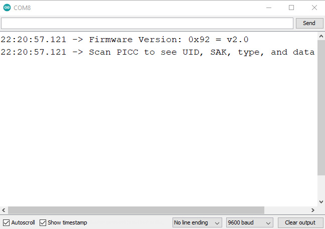
In the sketch, we send the tag code via the serial port, to view the code it is required to open the Serial Monitor of the Arduino IDE.
You should see something like the figure below:
Compare the RFID card or the keychain to the reader. Let the reader and the tag closer until all the information is displayed.
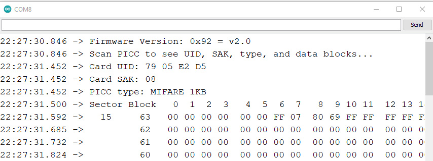
Copy Card UID
Demonstration – RFID Module With Arduino
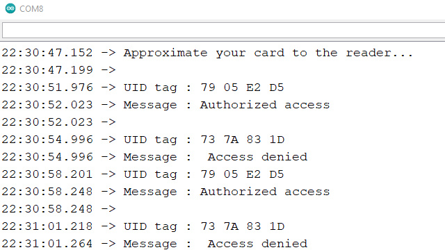
Now, upload the code to your Arduino and open the serial monitor, and swipe the card that comes with the RC522 RFID reader. You will see something similar to the following image.
Code For Access Card
|
1 2 3 4 5 6 7 8 9 10 11 12 13 14 15 16 17 18 19 20 21 22 23 24 25 26 27 28 29 30 31 32 33 34 35 36 37 38 39 40 41 42 43 44 45 46 47 48 49 50 51 52 53 54 |
#include <SPI.h> #include <MFRC522.h> #define SS_PIN 10 #define RST_PIN 9 MFRC522 mfrc522(SS_PIN, RST_PIN); // Create MFRC522 instance. void setup() { Serial.begin(9600); // Initiate a serial communication SPI.begin(); // Initiate SPI bus mfrc522.PCD_Init(); // Initiate MFRC522 Serial.println("Approximate your card to the reader..."); Serial.println(); } void loop() { // Look for new cards if ( ! mfrc522.PICC_IsNewCardPresent()) { return; } // Select one of the cards if ( ! mfrc522.PICC_ReadCardSerial()) { return; } //Show UID on serial monitor Serial.print("UID tag :"); String content= ""; byte letter; for (byte i = 0; i < mfrc522.uid.size; i++) { Serial.print(mfrc522.uid.uidByte[i] < 0x10 ? " 0" : " "); Serial.print(mfrc522.uid.uidByte[i], HEX); content.concat(String(mfrc522.uid.uidByte[i] < 0x10 ? " 0" : " ")); content.concat(String(mfrc522.uid.uidByte[i], HEX)); } Serial.println(); Serial.print("Message : "); content.toUpperCase(); if (content.substring(1) == "F0 60 AB A3") //Change this UID { Serial.println("Authorized access"); Serial.println(); delay(3000); } else { Serial.println(" Access denied"); delay(3000); } } |
From the first code, we get an RFID card tag value. Set those result card tag values in the below code in the function:
|
1 |
if (content.substring(1) == "F0 60 AB A3") //Change this UID |
Now after changing the tag value, upload the code.
Control LED With Valid Tags
Code ( verification of the registered tag ):
|
1 2 3 4 5 6 7 8 9 10 11 12 13 14 15 16 17 18 19 20 21 22 23 24 25 26 27 28 29 30 31 32 33 34 35 36 37 38 39 40 41 42 43 44 45 46 47 48 49 50 51 52 53 54 55 56 57 58 59 60 61 62 63 64 65 |
#include <SPI.h> #include <MFRC522.h> #define SS_PIN 10 //PIN SDA #define RST_PIN 9 //PIN RESET MFRC522 rfid(SS_PIN, RST_PIN); const int pinoLedVerde = 3; const int pinoLedVermelho = 2; void setup(){ Wire.begin(); SPI.begin(); rfid.PCD_Init(); pinMode(pinoLedVerde, OUTPUT); pinMode(pinoLedVermelho, OUTPUT); digitalWrite(pinoLedVerde, LOW); digitalWrite(pinoLedVermelho, LOW); } void loop() { leituraRfid(); } void leituraRfid(){ if (!rfid.PICC_IsNewCardPresent() || !rfid.PICC_ReadCardSerial()) return; String strID = ""; for (byte i = 0; i < 4; i++) { strID += (rfid.uid.uidByte[i] < 0x10 ? "0" : "") + String(rfid.uid.uidByte[i], HEX) + (i!=3 ? ":" : ""); } strID.toUpperCase(); /***END OF THE CODE BLOCK RESPONSIBLE FOR GENERATING THE READ RFID TAG***/ ////THE ADDRESS "27:41:AA:AB" MUST BE CHANGED TO THE ADDRESS OF YOUR RFID TAG THAT YOU PREVIOUSLY CAPTURED if (strID.indexOf("27:41:AA:AB") >= 0) { ////IF THE ADDRESS OF THE TAG READ IS EQUAL TO THE ADDRESS INFORMED, DO digitalWrite(pinoLedVerde, HIGH); //TURN ON THE GREEN LED delay(3000); //4 SECOND INTERVAL digitalWrite(pinoLedVerde, LOW); //TURN OFF THE GREEN LED }else{ //IF NOT, DO IT (IF THE TAG LIST IS NOT VALID) digitalWrite(pinoLedVermelho, HIGH); //TURN ON THE RED LED delay(3000); ////6 SECOND INTERVAL digitalWrite(pinoLedVermelho, LOW); //TURN OFF THE GREEN LED } rfid.PICC_HaltA(); //CARD READING STOP rfid.PCD_StopCrypto1(); //CRYPTOGRAPHY STOP IN PCD } |
Here are some more Posts for you:
- How to Use an LDR Sensor With Arduino Tutorial
- Explain MQ2, MQ3, MQ7 and MQ135 Gas Sensor With Arduino Tutorials
- Tutorial DS1307 RTC Module With Arduino
- Interface HC-SR04 Ultrasonic Sensor With Arduino
- Interface Rotary Encoder With Arduino, How It Works, Codes
- Interface SIM800L with Arduino Tutorial – How It Works, Codes

1 Comment
Pingback: IoT RFID Attendance System Based On ESP8266 And PHP Mysql