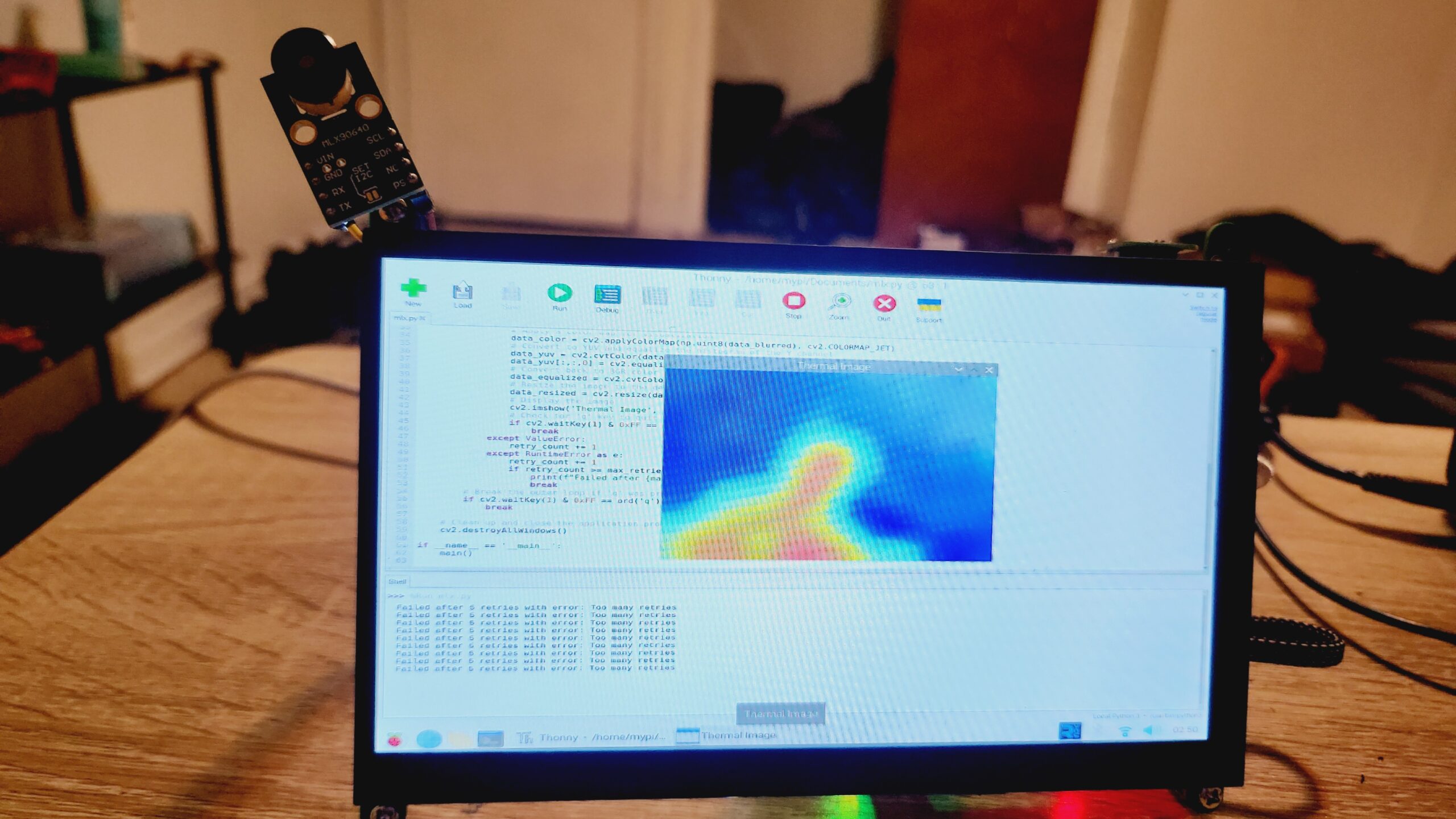
Hey there! In this tutorial, we’ll guide you on how to use the MLX90640 thermal imaging camera with Raspberry Pi to detect heat and measure temperature. Just Connect the MLX90640 IR thermal camera to your Raspberry Pi via the I2C interface, and it’ll show you the shape of objects in front of it. Your Pi processes the data and shows it as a thermal image on Display.
Thank You, NextPCB!
This project was made possible with the help of NextPCB. If you require PCB services in your perojects, check out NextPCB’s website for options like PCB assembly and an online Gerber Viewer. Just to let you know, they’re currently offering free PCB assembly for 5 PCs.
Required Material
- Raspberry Pi
- MLX90640 IR Temperature Sensor
- Display
- Jumper Wires
MLX90640 32×24 IR Array Temperature Sensor
This thermal imaging camera features a 32 × 24 pixel array with a 55° field of view, connecting through the I2C interface. It’s compatible with 3.3V/5V operating voltage and works with Raspberry Pi, Arduino, ESP32, and STM32.
MLX90640 infrared sensor is an affordable option for different applications of thermal analysis needs. It’s inexpensive compared to high-end thermal cameras and has a 32×24 pixel resolution excellent for fire prevention, smart buildings, surveillance, and much more. It Operating temperature between -40°C to 85°C, and it accurately measures temperatures from -40°C to 300°C with an accuracy of ±1°C.
Plus, it doesn’t need regular calibration like other sensors. The compact design with a digital interface makes it easy to use in your projects.
The MLX90640 also features an ambient temperature sensor and a supply voltage sensor, increasing its accuracy and reliability. All sensor data, including ambient and supply voltage readings, are saved in internal RAM and accessible through an I2C interface.
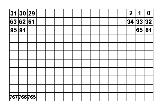
The MLX90640 Thermal Camera features a total of 768 IR detector sensors or pixels. Each pixel is designated by its row (from 1 to 24) and column (from 1 to 32) position as Pixel(i, j).
These pixels capture temperature data, providing accurate thermal imaging and temperature measurements across the camera’s field of view.
Features & Specifications
- Small size, low-cost 32×24 pixels IR array
- Factory-calibrated and easy-to-integrate
- Noise Equivalent Temperature Difference (NETD): 0.1K RMS @1Hz refresh rate
- I2C compatible digital interface with a programmable refresh rate (0.5Hz to 64Hz)
- Two FOV options: 55°x35° and 110°x75°
- Measuring range: -40°C~300°C
- Temperature resolution: 0.1°C
- Measurement accuracy: ±2°C
- Repeatability: ±2°C
- Response frequency: 8Hz
- Working voltage: 3.3~5V
- Working current: 42mA
- Working temperature: -40°C~85°C
- Size: 17.27mm x 33mm
- Compliant with RoHS regulations
Application
- Accurate non-contact temperature detection
- Infrared thermal imaging and thermometry
- Smart Home, Building, Lighting
- Industrial temperature control, security
- Microwave ovens
- Industrial temperature control of moving
parts - Visual IR thermometers
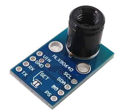
MLX90640 Pinout
- VCC: Connect to 3.3V (MCU)
- GND: Connect to GND (MCU)
- SDA: Connect to SDA pin of I2C interface (MCU)
- SCL: Connect to SCL pin of I2C interface (MCU)
Communication Of MLX90640 Imaging Camera

The MLX90640 Thermal Camera uses an I2C communication protocol, supporting high-speed mode up t 1MHz. It operates just as a slave device on the I2C bus.
The SDA and SCL ports tolerate 5V voltage and connect directly to the 5V I2C bus. The device address can be programmed with up to 127 addresses, with a default value of 0x33. During data transmission, three signals are involved: start, end, and response.

- The master communicates with the slave by sending a 7-bit slave address after initiating a START condition.
- The first seven bits represent the address, while the 8th bit is the read/write (R/W) bit.
- The R/W bit defines the transfer direction: high indicates the master will read data from the slave, and low indicates the master will send data to the slave.
Memory and registers Of MLX90640 Imaging Camera
The below table shows the RAM distribution and control registers of the MLX90640. The RAM area has two data modes, while the EEPROM stores calibration constants and device structure parameters.
| Address Range | Description |
|---|---|
| 0x0000 – 0x03FF | ROM |
| 0x0400 – 0x07FF | RAM |
| 0x2400 – 0x273F | EEPROM |
| 0x800D – 0x8010 | Registers |
| 0x8000 – 0x800C | Registers (MLX reserved) |
| 0x8011 – 0x8016 | Registers (MLX reserved) |
MXL90640 memory map
Refresh Rate of Thermal Imaging Camera
- This module supports 8 refresh rates, with a maximum of 64Hz.
- The refresh rate is configured using registers 1” (0x800D).
The settings for the 8 refresh rates are defined by bits 7, 8, and 9 of control register 1 (0x800D). MLX90640 is calibrated in Chess pattern mode by default, resulting in better fixed pattern noise behavior. For optimal performance, it’s suggested to use the Chess pattern mode.
Infrared Temperature Measurement Principle
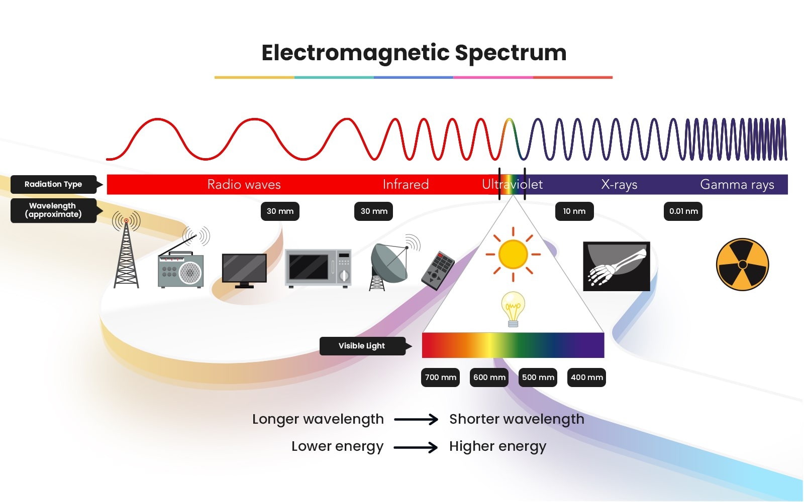
Temperature measurement using infrared radiation depends on the Planck and Boltzmann radiation laws. Each object emits electromagnetic radiation from its surface, proportional to its temperature. This emitted radiation contains infrared radiation, which is captured by infrared sensors. Checkout Infrared-Basics.pdf
The sensor detects this radiation and then processes it digitally to generate an output signal proportional to the object’s temperature. The accuracy of measurement depends on aspects like emissivity, which defines the relationship between real radiation and that of a black body.
Emissivity is crucial; a black body has an emissivity of 1, but most objects have lower emissivity. Sensors are calibrated using radiators with a known emissivity, typically close to 0.99.
Objects with constant emissivity across wavelengths are called grey bodies, while those with emissivity varying with temperature and wavelength, like metals, are selective radiators. Emissivity compensates for the difference between these bodies and black bodies.
The infrared sensor not only detects radiation emitted by the object but also reflects radiation from surroundings and potentially infrared radiation penetrating the object.
Measurement Distance
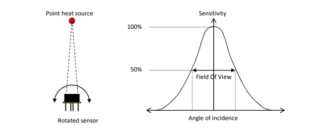
The Field of View (FOV) of this module is defined by the 50% radiation signal received by the thermopile and is influenced by the sensor’s main axis. The temperature measured is a weighted average of the detected object’s temperature within the FOV. To enhance accuracy, ensure the detected object is fully within the FOV.
Interfacing MLX90640 Thermal Imaging Camera with Raspberry PI
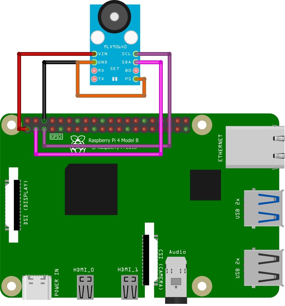
Connect VCC to a 3.3V pin and GND to a ground pin on the Raspberry Pi. SDA should be connected to GPIO 3, and SCL to GPIO 5 on the Raspberry Pi.
Note: Some sensors may not work initially. After spending a day troubleshooting, I discovered that Connecting PS to GND resolved the issue.
| Pin | Connection |
|---|---|
| VCC | Connect to one of the 3.3V pins on the Raspberry Pi |
| GND | Connect to one of the ground pins on the Raspberry Pi |
| SDA | Connect to the SDA pin on the Raspberry Pi GPIO (Pin 3) |
| SCL | Connect to the SCL pin on the Raspberry Pi GPIO (Pin 5) |
After correctly wiring the MLX90640, we can verify its registration on the Raspberry Pi’s I2C port using the following command.
First, enable I2C functionality on the Raspberry Pi, you’ll need to install the necessary tools:
|
1 2 |
sudo apt-get install -y python-smbus sudo apt-get install -y i2c-tools |
After installing the required packages, you can use the following command to check if the I2C devices are connected:
|
1 |
sudo i2cdetect -y 1 |
After running the sudo i2cdetect -y 1 command, you should see an output similar to the following printed on the terminal:
|
1 2 3 4 5 6 7 8 |
0 1 2 3 4 5 6 7 8 9 a b c d e f 00: -- -- -- -- -- -- -- -- -- -- -- -- -- -- -- -- 10: -- -- -- -- -- -- -- -- -- -- -- -- -- -- -- -- 20: -- -- -- -- -- -- -- -- -- -- -- -- -- -- -- -- 30: -- -- -- 33 -- -- -- -- -- -- -- -- -- -- -- -- 40: -- -- -- -- -- -- -- -- -- -- -- -- -- -- -- -- 50: -- -- -- -- -- -- -- -- -- -- -- -- -- -- -- -- 60: -- -- -- -- -- -- -- -- -- -- -- -- -- -- -- -- |
The number 33 is printed, confirming the I2C address of the MLX90640 (0x33).
Source Code & libriries
To read data from the MLX90640 thermal Camera board using the Adafruit library, you need to install the library first.
|
1 |
pip install adafruit-circuitpython-mlx90640 |
Finally, open IDLE or Thonny, copy the code below, paste it into the IDE, and run the code:
|
1 2 3 4 5 6 7 8 9 10 11 12 13 14 15 16 17 18 19 20 21 22 23 24 25 26 27 28 29 30 31 32 33 34 35 36 37 38 39 40 41 42 43 44 45 46 47 48 49 50 51 52 53 54 55 56 57 58 59 60 61 62 |
import cv2 import numpy as np import time import board import busio import adafruit_mlx90640 def initialize_sensor(): # Initialize the I2C bus and MLX90640 sensor i2c = busio.I2C(board.SCL, board.SDA) mlx = adafruit_mlx90640.MLX90640(i2c) # Set the refresh rate to 4 Hz mlx.refresh_rate = adafruit_mlx90640.RefreshRate.REFRESH_4_HZ return mlx def main(): mlx = initialize_sensor() frame = np.zeros((24*32,)) # Buffer for sensor data max_retries = 5 desired_size = (640, 480) # Desired window size for display while True: retry_count = 0 while retry_count < max_retries: try: # Capture the frame from the thermal camera mlx.getFrame(frame) # Reshape and normalize the data data_array = np.reshape(frame, (24, 32)) data_normalized = cv2.normalize(data_array, None, 0, 255, cv2.NORM_MINMAX) # Apply Gaussian Blur data_blurred = cv2.GaussianBlur(data_normalized, (5, 5), 0) # Apply a color map for visualization data_color = cv2.applyColorMap(np.uint8(data_blurred), cv2.COLORMAP_JET) # Convert to YUV and equalize the histogram of the Y channel data_yuv = cv2.cvtColor(data_color, cv2.COLOR_BGR2YUV) data_yuv[:,:,0] = cv2.equalizeHist(data_yuv[:,:,0]) # Convert back to BGR color space data_equalized = cv2.cvtColor(data_yuv, cv2.COLOR_YUV2BGR) # Resize the image to the desired size data_resized = cv2.resize(data_equalized, desired_size, interpolation=cv2.INTER_LINEAR) # Display the image cv2.imshow('Thermal Image', data_resized) # Check for 'q' key to quit the application if cv2.waitKey(1) & 0xFF == ord('q'): break except ValueError: retry_count += 1 except RuntimeError as e: retry_count += 1 if retry_count >= max_retries: print(f"Failed after {max_retries} retries with error: {e}") break # Break the outer loop if 'q' was pressed if cv2.waitKey(1) & 0xFF == ord('q'): break # Clean up and close the application properly cv2.destroyAllWindows() if _name_ == '_main_': main() |
The Visualization of the Temperatures
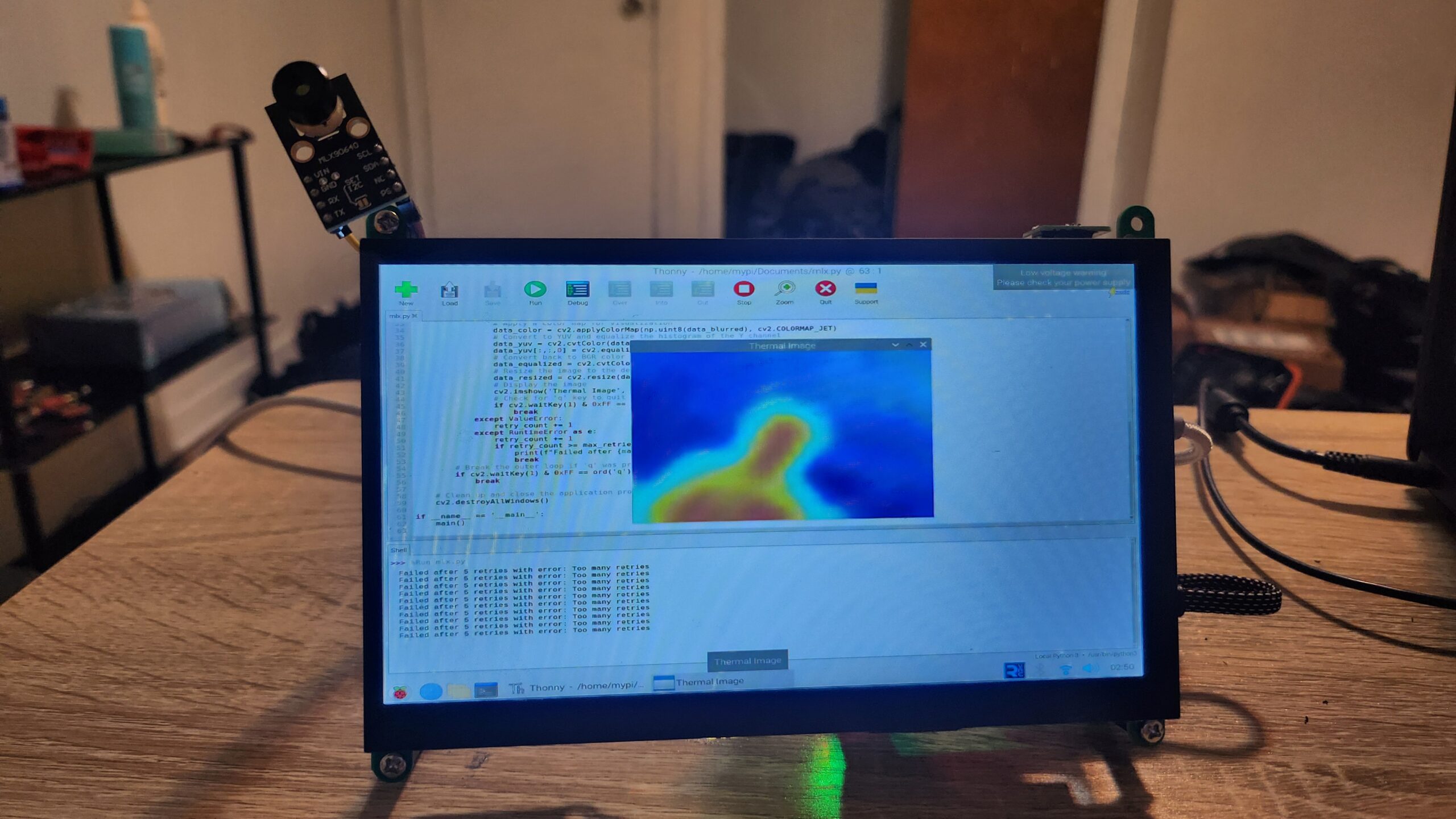
The program will take a moment to start up, but if everything goes correctly, you should now have a working thermal camera.
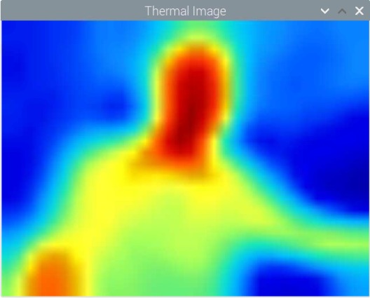
To display the 768 temperatures, I converted values from [0,180] to RGB values.
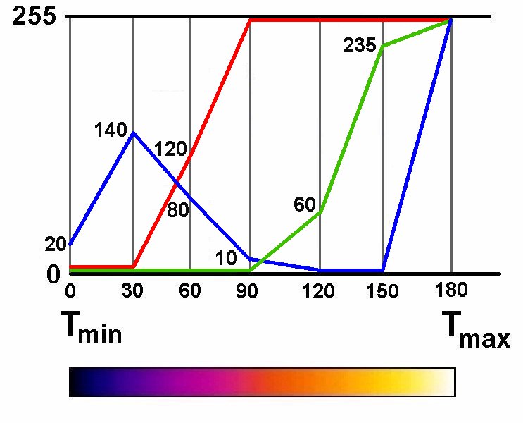
This results in colors resembling those seen in FLIR cameras. Above, you’ll find a test run with random temperatures.

