The agricultural sector worldwide is challenging water management. Inefficient irrigation practices often lead to over-irrigation, which not only leads to water but also affects crop yield because of diseases and waterlogging. Under-irrigation can lead to lower growth because of inadequate water supply.
In general, the majority of existing automatic irrigation systems are complex and expensive, limiting their widespread use, particularly in developing regions with vast agricultural landscapes.
These factors combine to create a pressing need for an improved approach to managing and conserving water in agriculture through precise soil moisture measurement and regulation.
Thank You, PCBWay
This project is successfully completed because of the support and help from PCBWay. Guys if you have a PCB project, please see their website and get exciting bargains and coupons.
PCBway is the best prototype PCB company offering great PCB boards at lower prices If you sign-up using this link you will get beginner and sign-up coupon rewards. https://www.pcbway.com
Capacitive Soil Moisture Sensor
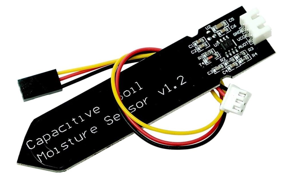
A Capacitive Soil Moisture Sensor is a device used in soil moisture monitoring to quantify the exact volumetric water content in soil. In contrast to resistive sensors that measure the soil’s conductivity to assess water content in soil, capacitive sensors estimate soil moisture levels from the soil’s dielectric permittivity.
This is an analog capacitive soil moisture sensor that measures soil moisture levels by capacitive sensing, i.e. capacitance is varied on the basis of water content present in the soil. The capacitance is converted into voltage level basically from 1.2V to 3.0V maximum.
Capacitive Soil Moisture Sensor extends their working life periods because of the anticorrosive resistance. These sensors are made of a corrosion-resistant material giving it a long service lifespan. Raspberry PI Soil Moisture Sensor Tutorial with Python Script (Schematics, code)
Features & Technical Details
- Output Type: Analog
- Operating Voltage: DC 3.3-5.5V
- Output Voltage: DC 0-3.0V
- Operating Current: 5mA
- Accuracy: ±3% volumetric water content (VWC)
- Linearity: Highly Linear up to 85% (Slightly negligible drift afterward)
- Sensitivity: Highly Sensitive (detect small changes in soil moisture levels)
Specifications
- The sensor employs analog capacitive sensing technology to measure soil moisture levels, setting it apart from other sensors that typically use resistive sensing methods.
- Constructed with corrosion-resistant material, the sensor boasts extended durability and a long service life.
- When inserted into the soil, the sensor provides real-time soil moisture data, a feature that impresses with its immediate and accurate readings.
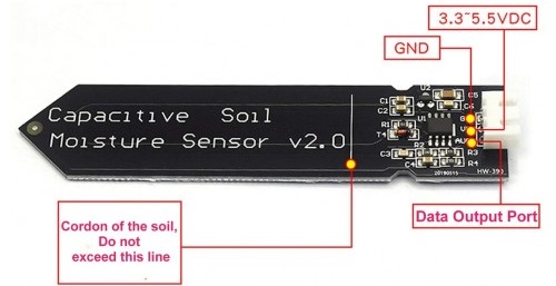
- The module incorporates an on-board voltage regulator. This allows it to operate within a voltage range of 3.3 to 5.5V, providing a wide range of compatibility..
Capacitive Soil Moisture Sensor Construction & Working
A Capacitive Soil Moisture Sensor is typically composed of two main parts:
- Sensor Probes: These act as the capacitor in the circuit and are generally made from a conductive material such as copper or stainless steel. They are placed in a parallel configuration to act as the two plates of a capacitor. The soil in which the sensor is inserted acts as the dielectric medium between these plates.
- Circuitry: The circuitry, which includes the 555 Timer IC, is responsible for generating the square wave that is fed to the sensor probes.
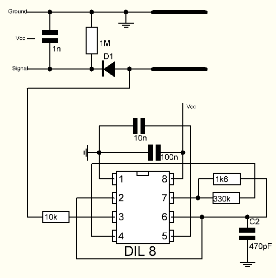
The 555 Timer IC generates a frequency fix square wave. This wave is applied to the soil moisture sensor probes, creating a reactance that depends on the soil’s moisture content. Together with a 10k ohm resistor, this reactance forms a voltage divider. The voltage at the intersection changes based on the sensor’s capacitance, which relates to soil moisture.
As moisture increases, capacitance rises, reducing reactance and allowing more of the square wave to pass through. This lowers the voltage at the signal line. Conversely, as soil dries, reactance increases, resulting in a higher voltage at the signal line.
The Arduino measures this voltage using its analog input pin, providing an estimation of soil moisture. This data enables control of irrigation systems, environmental monitoring, and various other applications.
Basic Usage & Installation
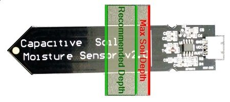
The probe is inserted into the soil to be monitored. The horizontal line shows the maximum depth that the probe should be inserted. The green area shown to the right is the recommended depth to place the probe. It is essential that the electronics at the top of the probe are not subject to water or water splashing to avoid damage.
The analog output of the probe is monitored by the analog input on an MCU like an Arduino. measurement range between wet soil and dry soil is determined experimentally by measuring the soil under different conditions and the software configured to detect when the soil is too dry, too wet, or just right.
System Design & Representation
The proposed project “Soil Moisture Measurement with Automatic Irrigation System” operates through a series of interconnected sensors and modules, each with a specific task explained below
Block Diagram
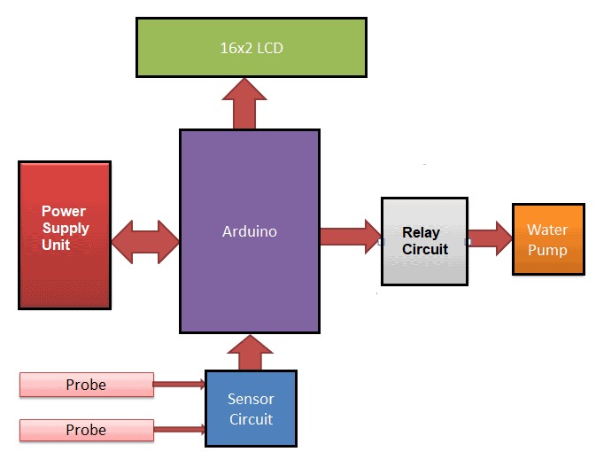
Here’s a brief overview of the block diagram of our project.
- Power Supply Unit: This is the source of power for all the components It is typically 12V DC voltage suitable for your circuitry. The 12V is converted into lower voltage using some voltage regulator IC (for instance, 5V for an Arduino).
- Arduino: The Arduino is the brain of the system. It is a microcontroller board that will handle the logic and control. It takes the input from the soil moisture sensor, processes the data, and then makes decisions based on that data – such as whether to turn on or off the water pump.
- LCD Display: The LCD Display is used to show real-time data from the moisture sensor and potentially other status information about the system. This allows the user to monitor the soil moisture level and the operational state of the system.
- Soil Moisture Sensor: The soil moisture sensor measures the moisture level in the soil and sends this data to the Arduino.
- Relay Control Circuit: This circuit acts as an intermediary between the low-voltage Arduino and the higher-voltage water pump. When the Arduino sends a signal to the relay (for instance, when it decides the soil is too dry), the relay closes its contacts, allowing power to flow from the power supply unit to the water pump.
- Water Pump: The water pump is activated when the relay control circuit closes. It pumps water from a reservoir to the soil, increasing the moisture level. When the soil moisture sensor detects that the soil is sufficiently wet, the Arduino will send a signal to open the relay, cutting off power to the water pump.
Each of these components works together to create an automatic irrigation system that can monitor soil moisture levels and adjust watering accordingly, thereby optimizing water usage and promoting healthy plant growth.
Circuit Diagram
Here is a schematic for this project designed using EasyEDA, an online Schematic & PCB design tool.
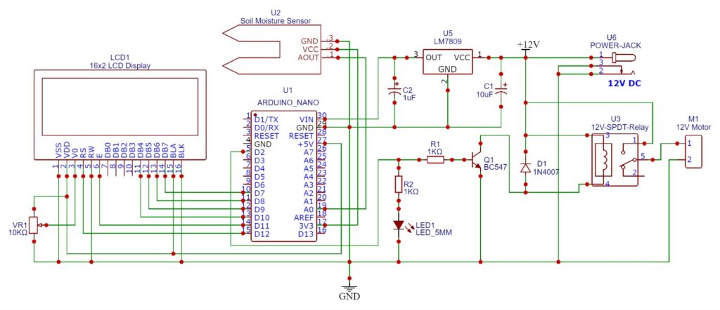
Starting from the Power supply unit, the entire device is powered by a 12V Power Supply using the 12V DC Power Adapter applied at the power Jack. We used a 12V power supply because the Relay and Motor required power is 12V. The 12V power is fed to the input terminal of the 7809 Voltage Regulator IC.
The 7809 Voltage Regulator IC converts 12V DC to 9V DC. We used two electrolytic capacitors 10uF and 1uF at input and out for smoothing the supply voltage. 9V DC is fed to Vin Pin of Arduino Nano Board. We could have directly fed 12V to Vin Pin of Arduino without using 7809 IC, but it would have heated the IC too much due to the large dropout voltage.
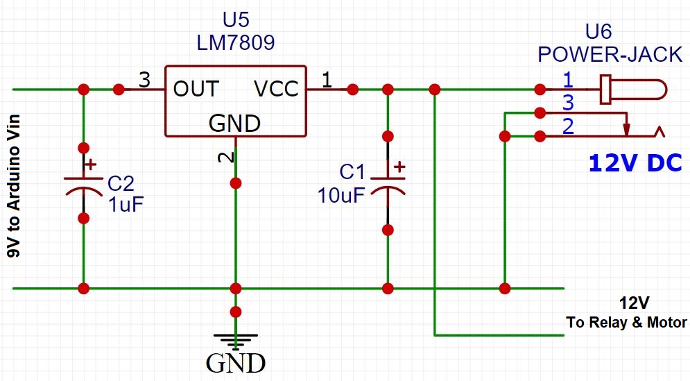
As Arduino Nano Board has a 5V Voltage Regulator IC. Hence the ATMEGA328 Microcontroller and other components can be powered using 5V & 3.3V pin of Arduino.
Arduino and Capacitive Soil Moisture Sensor
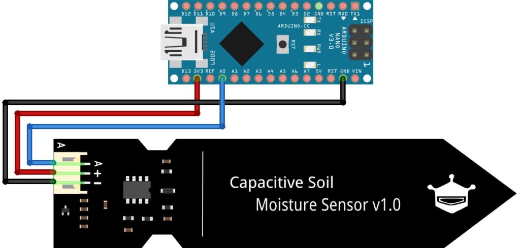
The Capacitive Soil Moisture Sensor has 3 pins VCC, GND & Aout. Hence, we connected Vin and GND to the 3.3V & GND pin of Arduino. The Aout Pin of Soil Moisture requires an analog pin to read data, which is connected to Analog Pin A0 of Arduino. Checkout previous post on How To Use Capacitive Soil Moisture Sensor v1.2 With Arduino Tutorial
Arduino and 16×2 Character LCD Display
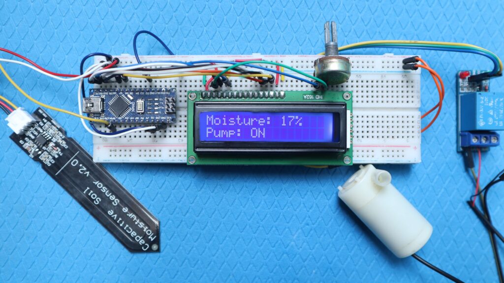
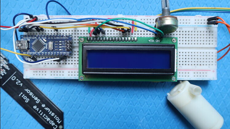
Moving to the LCD Display part, we have used a 16×2 Character LCD Display. The LCD will display the amount of Soil Moisture present in the Soil. Apart from Soil Moisture, it will also show the status of the motor whether it’s turned on or off.
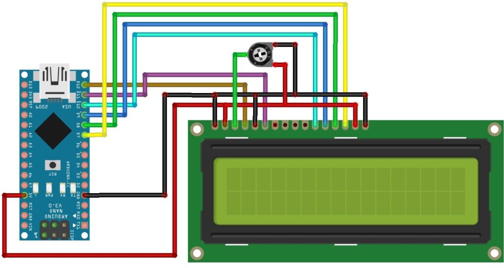
The LCD has 16 pins. The Pins 1, 5 & 7 of LCD are connected to GND. Similarly, Pin 2 and 15 are connected to VCC (5V). Pin number 3 is connected to a 10K potentiometer which is used to adjust the LCD Contrast. The LCD is controlled using the digital pin of Arduino.
The LCD Pins 4, 6, 11, 12, 13, 14 is connected to digital pin 12, 11, 10, 9, 8, 7 of Arduino Nano respectively. for this project, we used digital pin D2 of Arduino to turn on/off the relay.
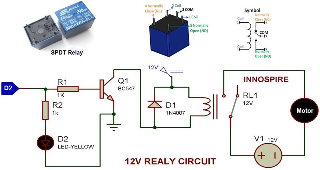
Here is the complete driver circuit.
The coil of the SPDT Relay is supplied with 12V Supply. The Relay has 3 pins for output controlling named as Normally Open (NO), Normally Closed (NC) and Common (COM). The NO pin of Relay is connected to Motor directly.
The NC is connected to a 12V supply. The other end of the Motor is connected to GND.
Calculations & Measurements
Practically, it is observed that when a soil moisture sensor is left in dry air the raw analog value given by the sensor is 600, which is 0% when mapped into percentage form.
A_min = 600
Similarly, when the soil moisture sensor is dipped into water, the raw analog value given by the sensor is 310, which is 100% when mapped into percentage form.
A_max = 310
To set the threshold value we first need to understand the relationship between the sensor reading and the Volumetric Water Content (VWC). We can calculate the value per percentage point using the total range of sensor readings.
The total range of sensor readings is 600 – 310 = 290.
Therefore, one percentage point is equal to 290 / 100 = 2.9 sensor units.
If you want to set the threshold at 40%, we would multiply this percentage by the value per percentage point and subtract the result from 600 (the value corresponding to 0%).
So, the threshold sensor reading A_t would be:
A_t = 600 – (40 * 2.9) = 484
This means that when your sensor reading drops to 484, it corresponds to 40% VWC, and the irrigation system should start watering according to our plan.
Arduino Code
Based on the above information, we developed a sample Arduino Code for this project. The code is based on taken from some reference article and has been modified using the Arduino IDE.
|
1 2 3 4 5 6 7 8 9 10 11 12 13 14 15 16 17 18 19 20 21 22 23 24 25 26 27 28 29 30 31 32 33 34 35 36 37 38 39 40 41 42 43 44 45 46 47 48 49 50 51 52 53 54 55 56 57 58 59 |
#include <LiquidCrystal.h> LiquidCrystal lcd(12, 11, 10, 9, 8, 7); const int AirValue = 600; const int WaterValue = 310; const int ThresholdValue = 484; int soilMoistureValue = 0; const int RelayPin = 2; void setup() { Serial.begin(9600); lcd.begin(16, 2); pinMode(RelayPin, OUTPUT); digitalWrite(RelayPin, HIGH); } void loop() { soilMoistureValue = analogRead(A0); Serial.println(soilMoistureValue); lcd.setCursor(0, 0); lcd.print("Moisture: "); float moisturePercentage = map(soilMoistureValue, AirValue, WaterValue, 0, 100); lcd.print(moisturePercentage, 0); lcd.print("%"); int upperLimit = ThresholdValue + 0.1 * (AirValue - WaterValue); int lowerLimit = ThresholdValue - 0.1 * (AirValue - WaterValue); if (moisturePercentage < 30.0) { digitalWrite(RelayPin, LOW); // turn on the relay lcd.setCursor(0, 1); lcd.print("Pump: ON "); } else if (moisturePercentage > 70.0) { digitalWrite(RelayPin, HIGH); // turn off the relay lcd.setCursor(0, 1); lcd.print("Pump: OFF"); } else { lcd.setCursor(0, 1); lcd.print("Pump: "); if (digitalRead(RelayPin) == LOW) { lcd.print("ON"); } else { lcd.print("OFF"); } } delay(250); lcd.clear(); } |
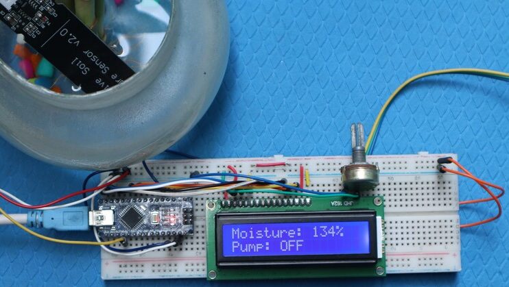
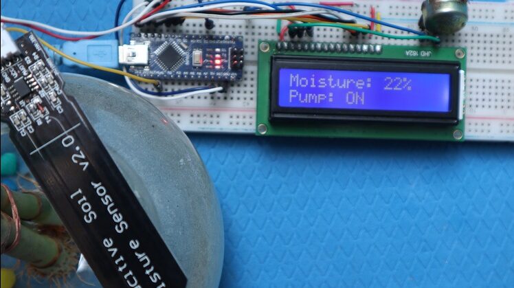
The code uses the LCD library to interface LCD with Arduino. The LCD will show the reading of ADC value, which can also be converted into a percentage value. The LCD will also show whether the Relay is turned on or not

