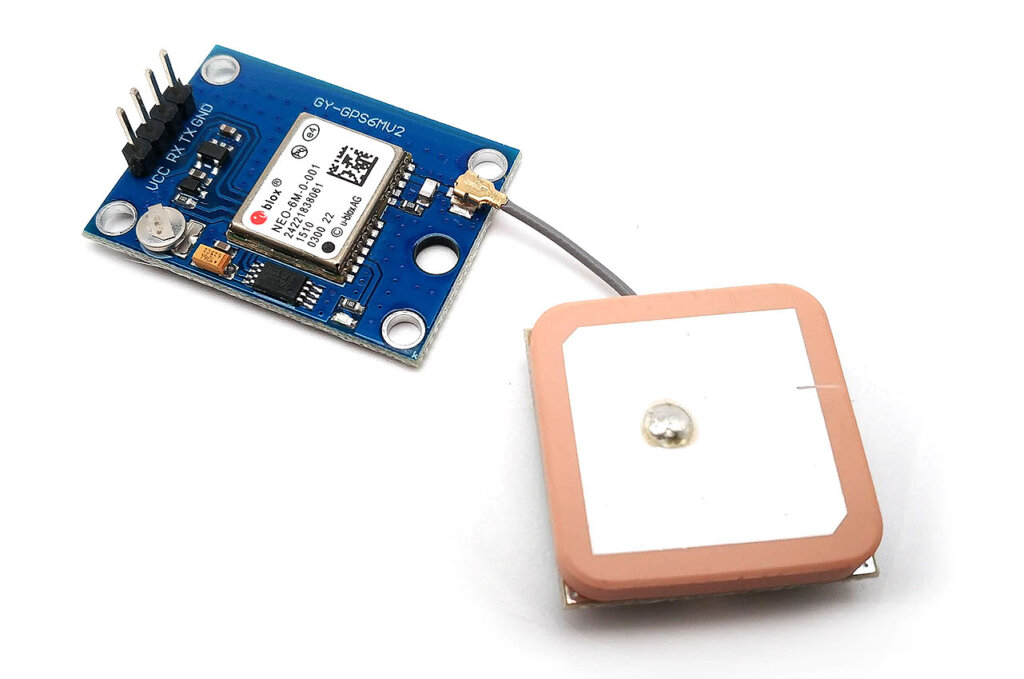
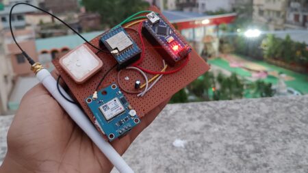
This tutorial shows you how to interface neo-6m GPS module with Arduino. The neo-6m GPS module is a GPS receiver that can be used to track the location of a device. The module can be used with a microcontroller to track the location of a device in real-time.
NEO-6M GPS module is a small device that helps us use GPS. It can track many satellites, uses low power, and has a special mode to save even more power.
By connecting the NEO-6M GPS module, you can access real-time positioning information, track movement, and enable location-aware functionalities. such as vehicle tracking, navigation systems, outside sports tracking, asset monitoring, and more.
Required Material
- Arduino board
- NEO-6M GPS module
- Jumper wires
- Breadboard
Ublox NEO-6M GPS Module Arduino
The Global Positioning System (GPS) is a network of satellites that help us to locate our position. These satellites constantly send out signals with information about their position and time. The NEO-6M GPS module, made by u-blox, is a small and portable device that is a key part of GPS systems.
The NEO-6M module can smoothly track up to 22 satellites using over 50 channels. It has low power consumption and drains the battery sparingly by consuming only 45mA of current.
It can work with an operating voltage range of 2.7V to 5V. In order to reduce the power consumption, the module has a built-in power-saving mode. When activated, the module consumes only 11mA of current.
Specification of NEO-6M GPS module
- Voltage: 2.7V to 5
- Current Consumption: 45mA (normal mode), 11mA (power-saving mode)
- Satellite Tracking: 22 satellites on over 50 channels
- Communication Protocol: NMEA
- Update Rate: Up to 5Hz
- Sensitivity: -161 dBm tracking, -147 dBm acquisition
- Antenna: Built-in patch antenna
- Dimensions:16mm x 16mm
- Operating Temperature: -40°C to +85°C
- Baud Rate: Configurable, default at 9600 (supports higher rates 115200)
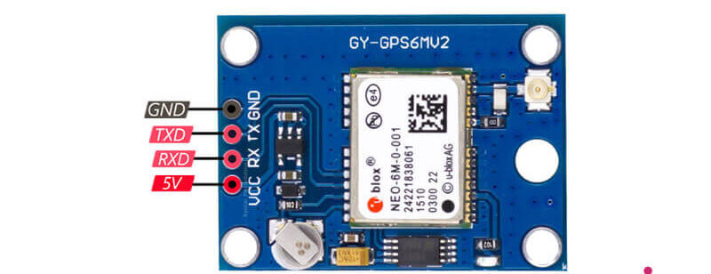
Pinout of NEO-6M GPS module
- VCC: Power supply pin (3.3V or 5V)
- GND: Ground pin
- TX: Transmit pin for data output
- RX: Receive pin for data input
Applications of NEO-6M GPS module
- Navigation systems
- Internet of Things (IoT) applications
- Smart Tracking devices
- Outdoor activities (hiking, camping, geocaching)
- Geofencing
- Robotics and drones
GPS NEO-6M Interfacing With Arduino
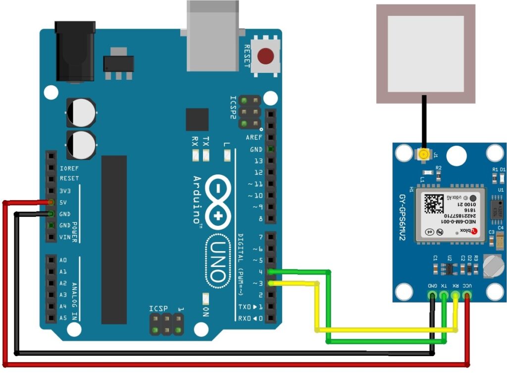
Connect the NEO-6M GPS module to your Arduino:
-
- VCC pin to Arduino 5V pin.
- GND pin to Arduino GND pin.
- RX pin to Arduino digital pin 3
- TX pin to Arduino digital pin 4
Reading GPS Data Code
|
1 2 3 4 5 6 7 8 9 10 11 12 13 14 15 16 17 18 19 20 21 22 23 24 25 26 27 28 29 30 31 |
#include <SoftwareSerial.h> // Define the Arduino pins for software serial communication const int RXPin = 4; const int TXPin = 3; // Set the default baud rate for the NEO-6M GPS module const int GPSBaud = 9600; // Create a software serial object for GPS communication SoftwareSerial gpsSerial(RXPin, TXPin); void setup() { // Start the hardware serial port for communication with the computer Serial.begin(9600); // Start the software serial port for GPS communication gpsSerial.begin(GPSBaud); } void loop() { // Check if there is data available from the GPS module while (gpsSerial.available() > 0) { // Read the incoming data and send it to the computer char data = gpsSerial.read(); Serial.write(data); } } |
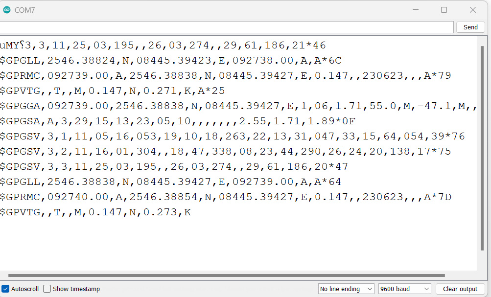
Connect Arduino to computer, open Arduino IDE, copy code to new sketch, upload to Arduino, open Serial Monitor, set the baud rate to 9600, and view GPS module output.
Ensure the correct connections between the Arduino and GPS module, and make sure the GPS module has a proper GPS signal.
NMEA Sentences
NMEA is an acronym that stands for the “National Marine Electronics Association“. The NMEA organization has developed a data communication standard to connect GPS devices and other marine electronics.
NMEA sentences are standardized data strings used in GPS and navigation systems. They are formatted in rows of comma-separated data fields called sentences. NEO-6M GPS module sends NMEA sentences at a specific update rate, typically once per second.
Two commonly used NMEA sentences are:
1. $GPRMC: Provides time, date, latitude, longitude, altitude, and velocity information.
Example: $GPRMC,123519, A,4807.038, N,01131.000, E,022.4,084.4,230394,003.1, W*6A
| Field | Description |
|---|---|
| $ | Every NMEA sentence starts with the $ character. |
| GPRMC | Global Positioning Recommended Minimum Coordinates |
| 123519 | Current time in UTC – 12:35:19 |
| A | Status (A=active or V=Void) |
| 4807.038, N | Latitude 48 deg 07.038′ N |
| 01131.000, E | Longitude 11 deg 31.000′ E |
| 022.4 | Speed over the ground in knots |
| 084.4 | Track angle in degrees True |
| 230394 | Current date – 23rd of March 1994 |
| 003.1, W | Magnetic Variation |
| *6A | Checksum data, always begins with * |
Each field in the NMEA sentence provides specific information, such as time, location, speed, and magnetic variation.
2. $GPGGA: Provides fix data, including 3D location and accuracy.
Example: $GPGGA,123519,4807.038,N,01131.000,E,1,08,0.9,545.4,M,46.9,M,,*47
| Field | Description |
|---|---|
| $ | Starting of NMEA sentence. |
| GPGGA | Global Positioning System Fix Data |
| 123519 | Current time in UTC – 12:35:19 |
| 4807.038,N | Latitude 48 deg 07.038′ N |
| 01131.000,E | Longitude 11 deg 31.000′ E |
| 1 | GPS fix (1 = fix, 0 = no fix) |
| 08 | Number of satellites being tracked |
| 0.9 | Horizontal dilution of position |
| 545.4,M | Altitude in Meters (above mean sea level) |
| 46.9,M | Height of geoid (mean sea level) |
| (empty field) | Time in seconds since last DGPS update |
| (empty field) | DGPS station ID number |
| *47 | Checksum data, always begins with * |
The $GPGGA NMEA sentence provides important GPS fix data, including information about time, latitude, longitude, GPS fix status, number of satellites tracked, altitude, and other parameters.
Installing TinyGPS++ Arduino library
Install the TinyGPS++ library. This library simplifies the parsing of NMEA data received from the GPS module. You can install it using the Arduino Library Manager or Download TinyGPS++ library
Arduino Code for Getting Live Location
|
1 2 3 4 5 6 7 8 9 10 11 12 13 14 15 16 17 18 19 20 21 22 23 24 25 26 27 28 29 30 31 32 |
#include <TinyGPS++.h> #include <SoftwareSerial.h> // GPS pin numbers const int GPS_RX_PIN = 4; const int GPS_TX_PIN = 3; // GPS baud rate const uint32_t GPS_BAUD_RATE = 9600; // The TinyGPS++ object TinyGPSPlus gps; // The serial connection to the GPS device SoftwareSerial gpsSerial(GPS_RX_PIN, GPS_TX_PIN); void setup() { Serial.begin(9600); gpsSerial.begin(GPS_BAUD_RATE); } void loop() { while (gpsSerial.available() > 0) { gps.encode(gpsSerial.read()); if (gps.location.isUpdated()) { Serial.print("Latitude: "); Serial.print(gps.location.lat(), 6); Serial.print(", Longitude: "); Serial.println(gps.location.lng(), 6); } } } |
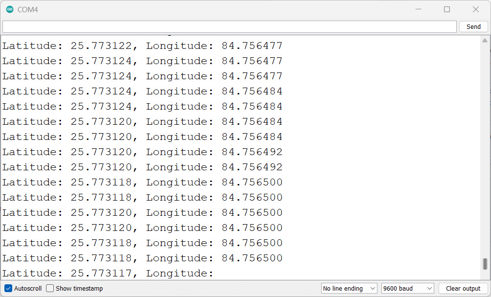
Once you have uploaded the code to your Arduino, you can open the Serial Monitor to view the latitude and longitude coordinates.
The Serial Monitor will display the GPS coordinates providing accurate location information. you can use these latitude and longitude values to track the device’s current location.
Arduino GPS Tracker using NEO-6M GPS Module & OLED Display
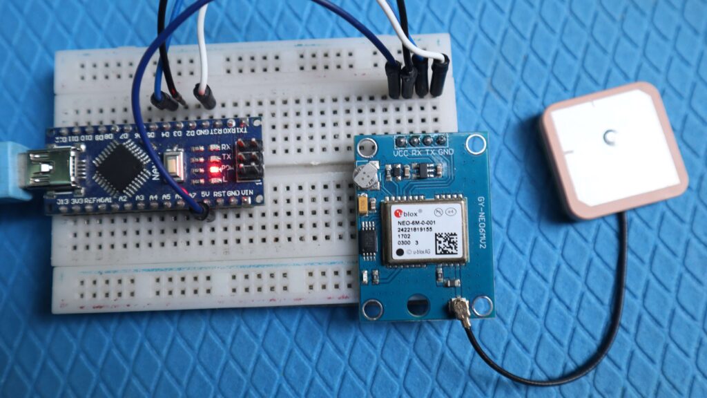
Now let us see the circuit diagram of Arduino GPS Tracker. The connection diagram is fairly simple as shown in the image below.
The GPS module has 4 pins. Connect the VCC & GND pin of GPS to the 3.3V-5V & GND pin of Arduino. The Rx & Tx pin of GPS goes to Arduino digital pin 3 & 4 respectively.
The OLED Display is an I2C Module. Connect the VCC & GND Pin of OLED to Arduino 5V & GND Pin. Similarly, connect the SDA & SCL pins to Arduino A4 & A5 pins respectively.
Source Code
The NEO-6M GPS module supports the TinyGPS++ library. To begin, download the library and add it to the Arduino library folder. This library makes it simple to extract GPS data received from the NEO-6M module.
Also, the code needs the Adafruit SSD1306 library, especially the Adafruit SSD1306 library with SSD1306 OLED displays.
Here is the full code. You can copy the code and upload it to the Arduino Nano Board.
|
1 2 3 4 5 6 7 8 9 10 11 12 13 14 15 16 17 18 19 20 21 22 23 24 25 26 27 28 29 30 31 32 33 34 35 36 37 38 39 40 41 42 43 44 45 46 47 48 49 50 51 52 53 54 55 56 57 58 59 60 61 62 63 64 65 66 67 68 69 70 71 72 73 74 75 76 |
#include <SPI.h> #include <Wire.h> #include <Adafruit_GFX.h> #include <Adafruit_SSD1306.h> #include <TinyGPS++.h> #include <SoftwareSerial.h> #define SCREEN_WIDTH 128 #define SCREEN_HEIGHT 32 #define OLED_RESET -1 #define SCREEN_ADDRESS 0x3C Adafruit_SSD1306 display(SCREEN_WIDTH, SCREEN_HEIGHT, &Wire, OLED_RESET); TinyGPSPlus gps; SoftwareSerial gpsSerial(4, 3); // RXPin, TXPin void setup() { Serial.begin(9600); gpsSerial.begin(9600); display.begin(SSD1306_SWITCHCAPVCC, SCREEN_ADDRESS); display.clearDisplay(); display.display(); delay(2000); } void loop() { while (gpsSerial.available() > 0) { if (gps.encode(gpsSerial.read())) { displayInfo(); } } if (millis() > 5000 && gps.charsProcessed() < 10) { Serial.println("No GPS detected"); while (true); } } void displayInfo() { display.clearDisplay(); display.setTextSize(1.5); display.setTextColor(SSD1306_WHITE); display.setCursor(0, 0); if (gps.location.isValid()) { display.print("Latitude: "); display.println(gps.location.lat(), 6); display.setCursor(0, 20); display.print("Longitude: "); display.print(gps.location.lng(), 6); Serial.print("Latitude: "); Serial.println(gps.location.lat(), 6); Serial.print("Longitude: "); Serial.print(gps.location.lng(), 6); } else { display.println("Location: NA"); Serial.println("Location: Not Available"); } display.display(); delay(100); } |
Testing
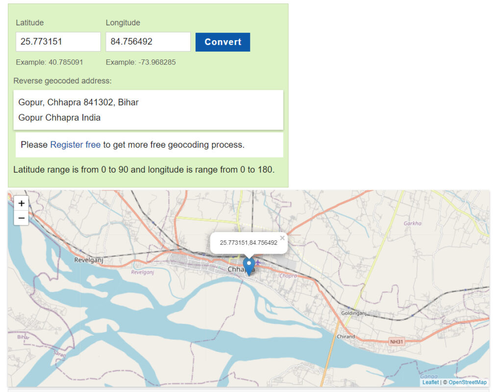
To check the latitude and longitude coordinates on a map, you can visit the website www.latlong.net. On this website, you can enter the latitude and longitude values obtained from your GPS module and visualize the corresponding location on the map.

