Introduction
In this tutorial we will learn how to Interface a 0.96″ OLED Display with Raspberry Pi Pico Board, The OLED display is one of the most popular and Attractive Displays available for a microcontroller.
The organic light-emitting diode (OLED) display that we’ll use in this tutorial is the SSD1306 model Display With Raspberry Pi Pico 0.96-inch display with 128×64 pixels.
Thank You NextPCB:
This project is successfully finished because of the help and sponsorship from NextPCB. Guys if you have a PCB project, please visit their website and get exciting discounts and coupons and more.
- Only 0$ for 5-10pcs PCB Prototypes:Nextpcb.com/pcbprototype
- Register and get $100 from NextPCB: Nextpcb.com/coupon
Why NextPCB
- Most Efficient, Economic, Inventive PCB Solutions
- Higher Quality
- Lower Price
- Faster Delivery
[the_ad id=”5035″]
Required Components – OLED Display with Raspberry Pi Pico
- Raspberry Pi PIco —>https://amzn.to/3LCIoWq
- OLED Display —>https://amzn.to/3LN8ohS
- Jumper wire —>https://amzn.to/3LN8ohS
OLED Display
An organic light-emitting diode (OLED )is a light-emitting diode (LED) in which the emissive electroluminescent layer is a film of organic compound that emits light in response to an electric current.
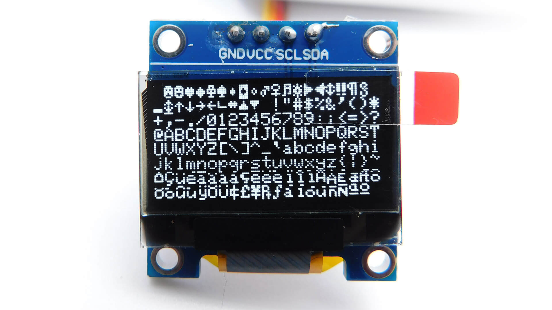
This is easy to use OLED display, 0.96” screen size, 128×64 resolution, and SSD1306 driver. You can connect to it via I2C
SSD1306 Module
The SSD1306 does communicate with the microcontroller to get the data and send it to the OLED screen to draw that data, Communication between the SSD1306 and the microcontroller, be it a Raspberry Pi Pico or an Arduino, is done via SPI or I2C.
- Generally, SPI communication is faster than I2C communication.
- In contrast, SPI communication requires more pins than I2C communication.
OLED screens have the advantage of having a very low consumption, around 20mA since only the necessary pixel is lit and they do not require a backlight. This is especially interesting in battery-powered applications.
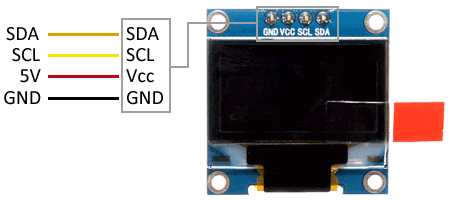
OLED Display Pinout
- GND: ground pin.
- VCC: is the power pin. The screen can be powered between 1.8V and 6V.
- SCL: is the clock signal pin of the I2C interface.
- SDA: It is the data signal pin of the I2C interface.
Specification:
- Driver: SSD1306
- Screen size: 0.96”
- Screen dimensions: 22 x 11 mm
- Resolution: 128 x 64 pixels
- Supply voltage: 3 – 5 V
- Module size: 27 x 27 x 3.5 mm
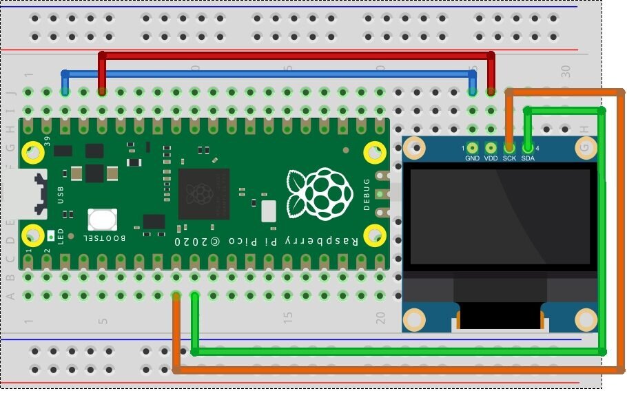
Wiring Diagram for OLED Display with Raspberry Pi Pico
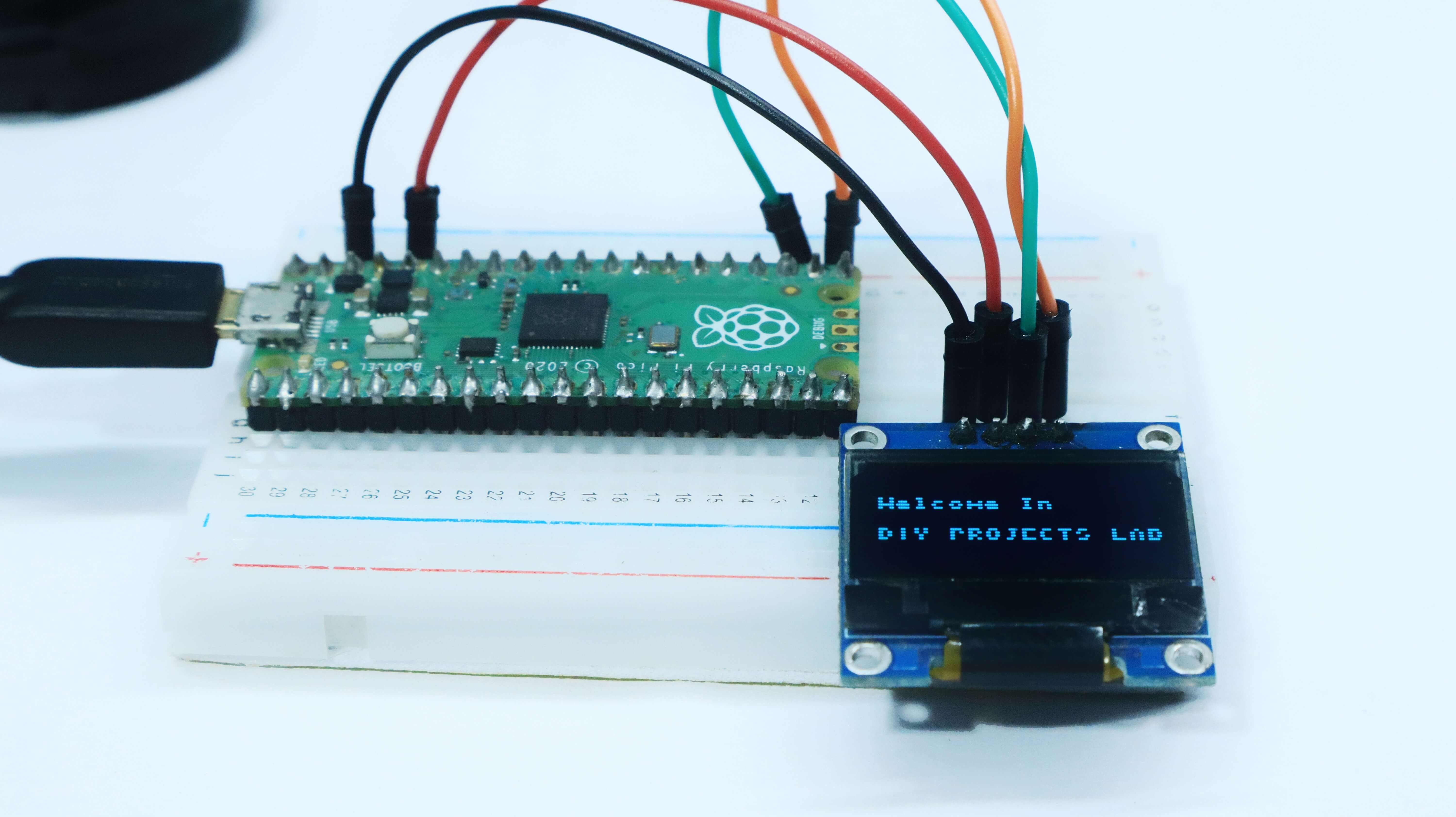
wiring is very simple. You just need to connect to the Raspberry Pi pico I2C pins as shown in the Below
| OLED Pin | Wiring to Raspberry Pi pico |
| Vin | 3.3V |
| GND | GND |
| SCL | GP9 |
| SDA | GP8 |
Source Code and Libraries for OLED Display with Raspberry Pi Pico
To control the OLED display with Micropython code you need the OLED libraries. Follow the next instructions to install those libraries.
The programming here is divided into two main parts:
1. SSD1306.py // this is SSD1306 Driver Code
2. Main.py // this is the main code
SSD1306.py
Firstly you need to create a new file in Thonny IDE. Copy the following code & save the file by the name ssd1306.py on Raspberry Pi Pico Board.
|
1 2 3 4 5 6 7 8 9 10 11 12 13 14 15 16 17 18 19 20 21 22 23 24 25 26 27 28 29 30 31 32 33 34 35 36 37 38 39 40 41 42 43 44 45 46 47 48 49 50 51 52 53 54 55 56 57 58 59 60 61 62 63 64 65 66 67 68 69 70 71 72 73 74 75 76 77 78 79 80 81 82 83 84 85 86 87 88 89 90 91 92 93 94 95 96 97 98 99 100 101 102 103 104 105 106 107 108 109 110 111 112 113 114 115 116 117 118 119 120 121 122 123 124 125 126 127 128 129 130 131 132 133 134 135 136 137 138 139 140 141 142 143 144 145 146 147 148 149 150 151 152 153 154 155 |
# MicroPython SSD1306 OLED driver, I2C and SPI interfaces from micropython import const import framebuf # register definitions SET_CONTRAST = const(0x81) SET_ENTIRE_ON = const(0xA4) SET_NORM_INV = const(0xA6) SET_DISP = const(0xAE) SET_MEM_ADDR = const(0x20) SET_COL_ADDR = const(0x21) SET_PAGE_ADDR = const(0x22) SET_DISP_START_LINE = const(0x40) SET_SEG_REMAP = const(0xA0) SET_MUX_RATIO = const(0xA8) SET_COM_OUT_DIR = const(0xC0) SET_DISP_OFFSET = const(0xD3) SET_COM_PIN_CFG = const(0xDA) SET_DISP_CLK_DIV = const(0xD5) SET_PRECHARGE = const(0xD9) SET_VCOM_DESEL = const(0xDB) SET_CHARGE_PUMP = const(0x8D) # Subclassing FrameBuffer provides support for graphics primitives # http://docs.micropython.org/en/latest/pyboard/library/framebuf.html class SSD1306(framebuf.FrameBuffer): def __init__(self, width, height, external_vcc): self.width = width self.height = height self.external_vcc = external_vcc self.pages = self.height // 8 self.buffer = bytearray(self.pages * self.width) super().__init__(self.buffer, self.width, self.height, framebuf.MONO_VLSB) self.init_display() def init_display(self): for cmd in ( SET_DISP | 0x00, # off # address setting SET_MEM_ADDR, 0x00, # horizontal # resolution and layout SET_DISP_START_LINE | 0x00, SET_SEG_REMAP | 0x01, # column addr 127 mapped to SEG0 SET_MUX_RATIO, self.height - 1, SET_COM_OUT_DIR | 0x08, # scan from COM[N] to COM0 SET_DISP_OFFSET, 0x00, SET_COM_PIN_CFG, 0x02 if self.width > 2 * self.height else 0x12, # timing and driving scheme SET_DISP_CLK_DIV, 0x80, SET_PRECHARGE, 0x22 if self.external_vcc else 0xF1, SET_VCOM_DESEL, 0x30, # 0.83*Vcc # display SET_CONTRAST, 0xFF, # maximum SET_ENTIRE_ON, # output follows RAM contents SET_NORM_INV, # not inverted # charge pump SET_CHARGE_PUMP, 0x10 if self.external_vcc else 0x14, SET_DISP | 0x01, ): # on self.write_cmd(cmd) self.fill(0) self.show() def poweroff(self): self.write_cmd(SET_DISP | 0x00) def poweron(self): self.write_cmd(SET_DISP | 0x01) def contrast(self, contrast): self.write_cmd(SET_CONTRAST) self.write_cmd(contrast) def invert(self, invert): self.write_cmd(SET_NORM_INV | (invert & 1)) def show(self): x0 = 0 x1 = self.width - 1 if self.width == 64: # displays with width of 64 pixels are shifted by 32 x0 += 32 x1 += 32 self.write_cmd(SET_COL_ADDR) self.write_cmd(x0) self.write_cmd(x1) self.write_cmd(SET_PAGE_ADDR) self.write_cmd(0) self.write_cmd(self.pages - 1) self.write_data(self.buffer) class SSD1306_I2C(SSD1306): def __init__(self, width, height, i2c, addr=0x3C, external_vcc=False): self.i2c = i2c self.addr = addr self.temp = bytearray(2) self.write_list = [b"\x40", None] # Co=0, D/C#=1 super().__init__(width, height, external_vcc) def write_cmd(self, cmd): self.temp[0] = 0x80 # Co=1, D/C#=0 self.temp[1] = cmd self.i2c.writeto(self.addr, self.temp) def write_data(self, buf): self.write_list[1] = buf self.i2c.writevto(self.addr, self.write_list) class SSD1306_SPI(SSD1306): def __init__(self, width, height, spi, dc, res, cs, external_vcc=False): self.rate = 10 * 1024 * 1024 dc.init(dc.OUT, value=0) res.init(res.OUT, value=0) cs.init(cs.OUT, value=1) self.spi = spi self.dc = dc self.res = res self.cs = cs import time self.res(1) time.sleep_ms(1) self.res(0) time.sleep_ms(10) self.res(1) super().__init__(width, height, external_vcc) def write_cmd(self, cmd): self.spi.init(baudrate=self.rate, polarity=0, phase=0) self.cs(1) self.dc(0) self.cs(0) self.spi.write(bytearray([cmd])) self.cs(1) def write_data(self, buf): self.spi.init(baudrate=self.rate, polarity=0, phase=0) self.cs(1) self.dc(1) self.cs(0) self.spi.write(buf) self.cs(1) |
main.py
Open a new tab again in the Thonny IDE. Copy the following below code and paste it onto the Thonny IDE new tab. Save the file by the name main.py in Raspberry Pi Pico.
|
1 2 3 4 5 6 7 8 9 10 11 12 13 14 15 |
import machine import ssd1306 import time oled = ssd1306.SSD1306_I2C(128, 64, machine.I2C(0)) oled.text("Hello everyone", 0, 8) oled.show() time.sleep(2) oled.text("Welcome In", 0, 30) oled.text("DiY PROJECTS LAB", 0, 40) oled.show() time.sleep(2) oled.text("Thank You", 0, 50) oled.show() |
Conclusion
After the Upload code, You will see that the OLED Start Texting is on Display.
[the_ad id=”5038″]
Read Similar Articles:
- Getting Started Raspberry Pi Pico – Pinout, Specs – Beginner Guide
- Interfacing PIR Motion Sensor with Raspberry Pi Pico
- Raspberry Pi Pico Home Automation System
- Interface Servo Motor With Raspberry Pi Pico
- Interface 0.96″ OLED Display with Raspberry Pi Pico
- Raspberry Pi Pico Weather Station Using Dht11 Sensor
- Interface 16*2 LCD Display With Raspberry Pi Pico


1 Comment
Pingback: Raspberry Pi With Ultrasonic Sensor Tutorial 2022