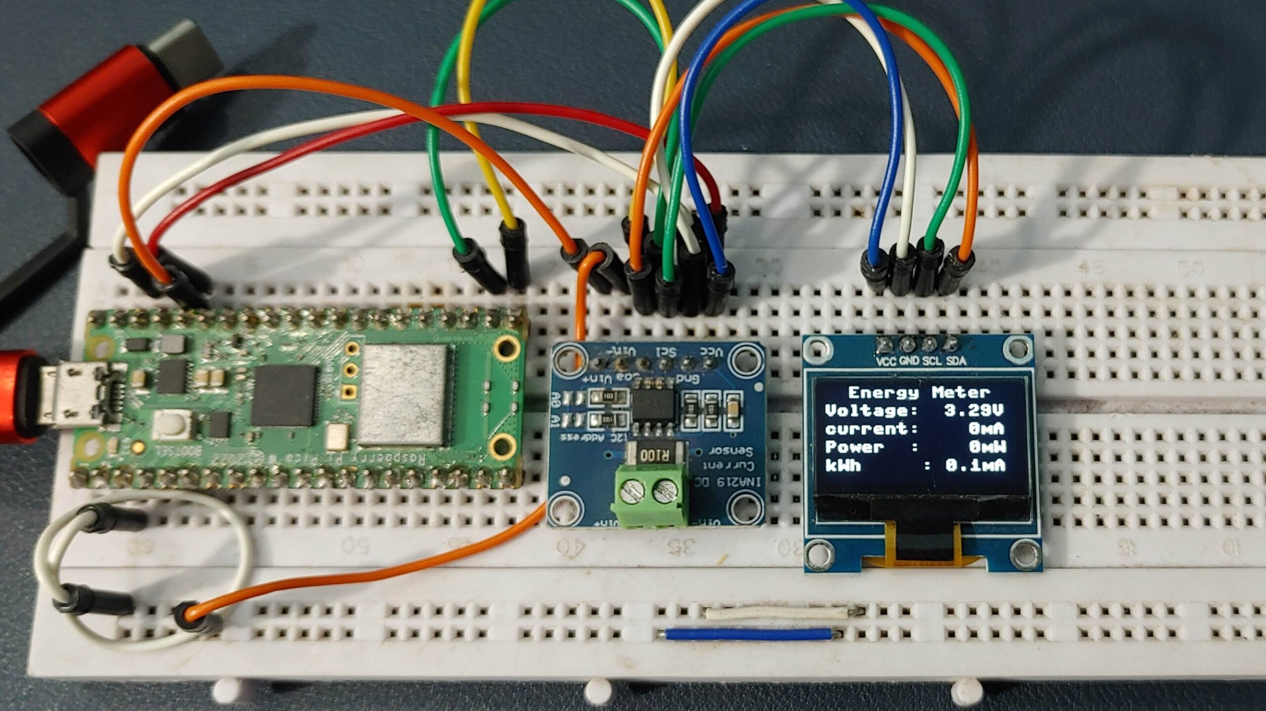
This tutorial shows you how to make a Raspberry Pi Pico-based Power Energy Meter usingINA219 Current Sensor With Micropython Script. This Energy Metere can measure Voltage, current, Power, and energy consumption using an INA219 current sensor and then shows its Output on a 0.96″ OLED display.
For voltage and current measurement with Pi Pico, you normally use analog input for voltage and a shunt resistor for current. However, this method has limitations, Rather, you can use an INA219 Current Sensor, which simplifies the procedure.
It uses a 0.1Ω shunt resistor on the module, can measure voltages up to 0-26volt, and currents up to 3.2A which is ±3.2Amp (bi-directional). The IC communicates via I2C, and Adafruit provides libraries with functions for easy reading of voltage and current values. The 0.1ohm shunt resistor sets the max current on the module.
Some features of this Energy meter
- Target voltage: Up to +26V
- Current measurement: Up to ±3.2A with ±0.8mA resolution
- Bus voltage sensing range: 0V to 26V
Required Material
- Raspberry Pi Pico
- INA219 current sensor
- 0.96″ i2c OLED
- Breadboard
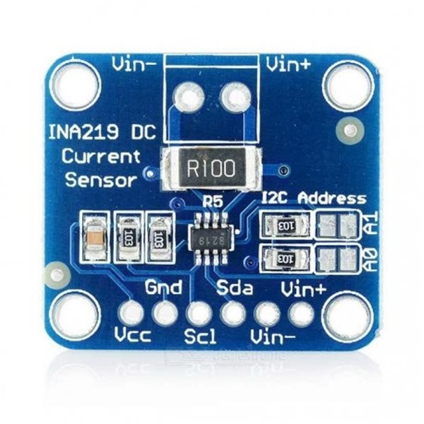
INA219 DC Current Sensor
The INA219 is a DC sensor commonly used in electronic projects to measure and monitor current flow. It is a high-precision sensor capable of measuring current up to 3.2A with a resolution of 0.1mA.
it operates with a method where a small resistor is placed in series with the load, and the INA219 converts the voltage across this resistor to determine the amount of current flowing through it. it uses the I2C communication protocol, allowing for easy integration with other I2C devices. How to use DC INA219 Current Sensor Module with Arduino
Checkout our previous post on Energy Meter
- Arduino Energy Meter Using INA219 DC Current Sensor
- ESP32-Based Energy Meter Using INA219 Current Sensor
- IoT Smart DC Energy Meter with ESP32 & ThingSpeak
How INA219 Work?
The INA219 Current Sensor uses the Hall effect principle and contains an onboard shunt resistor. It measures the voltage drop across the shunt resistor generated by the current passing through it. By measuring the voltage across the shunt resistor and applying calibration, it accurately calculates the current flow.
The chip communicates these measurements via the I2C or SMBus interface, allowing accurate real-time monitoring and control of current and voltage in electronic circuits. This makes it widely used for applications needing accurate power consumption measurement.
Specifications
- Resistor: 0.1 ohms, 1% accuracy, 2W power.
- Voltage Range: Up to +26V.
- Current Measurement: ±3.2A with ±0.8mA resolution.
- Size: 0.9″ x 0.8″ PCB.
- Voltage Sensing: 0V to 26V range.
- Interface: I2C communication.
- Data: Measures current, voltage, and power.
- Addresses: 16 programmable addresses.
- Filtering: Filtering options available.
- Calibration: Calibration registers included
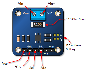
Pinout of INA219 Current Sensor
The INA219 sensor module has the following pins:
- VCC: Operating voltage (3.3V to 5.5V)
- GND: Ground pin
- SCL: Clock line for I2C interface.
- SDA: Data line for I2C interface.
- Vin-: Connects to the negative terminal of the voltage supply.
- Vin+: Connects to the positive terminal of the voltage supply.
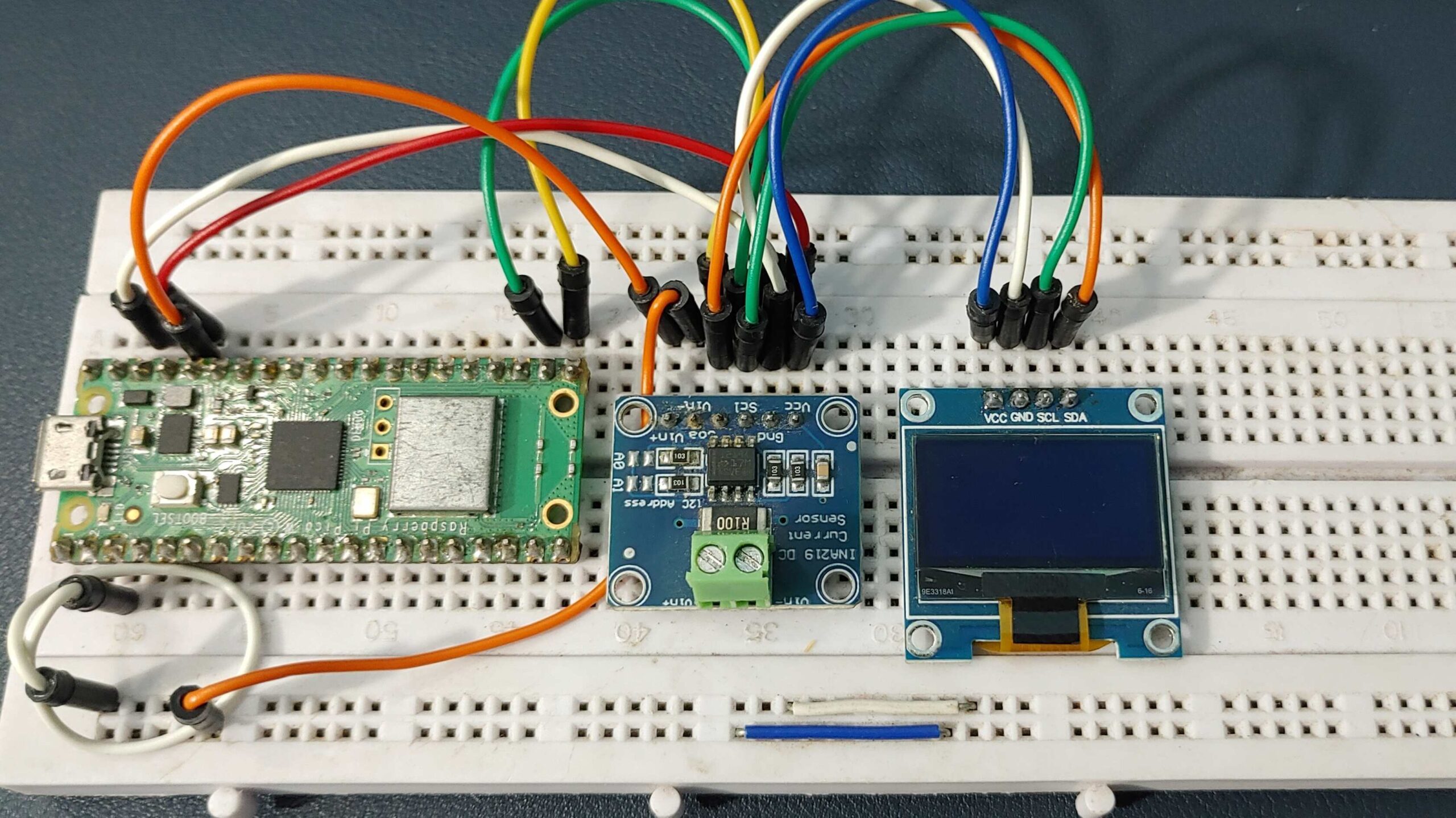
Wiring Diagram & Connections
Connections for this setup are quite straightforward to understand.
INA219 / OLED -> Raspberry Pi Pico
- Connect the VCC of the OLED and INA219 to the 3.3V (Vin) on the Pico.
- Connect the GND of the OLED and INA219 to a GND pin on the Pico.
- Connect the SDA of the OLED and INA219 to a GP16 pin on the Pico.
- Finally, connect the SCL Pin of the OLED and INA219 to the GP17 pin on the Pico.
To make connections, use a breadboard with jumper wires to easily connect the OLED and INA219 to the Raspberry Pi Pico board, eliminating the need for soldering.
MicroPython Code & Libraries
Let’s write a MicroPython Code For Raspberry Pi Pico-Based Energy Meter Using INA219 & get the temperature readings on an OLED Display.
The code for Raspberry Pi Pico Energy Meter is divided into three parts:
- ssd1306.py
- INA219.py
- main.py
The main code uses a library for the INA219 Module and the SSD1306 OLED display, providing all the necessary functions to read data from the Current Sensor and display it on the OLED Display.
ssd1306.py
To use the SSD1306 OLED Display, we also need a library. Open a new tab in the Thonny IDE and paste the provided code. Save the file as “ssd1306.py” on the Raspberry Pi Pico.
|
1 2 3 4 5 6 7 8 9 10 11 12 13 14 15 16 17 18 19 20 21 22 23 24 25 26 27 28 29 30 31 32 33 34 35 36 37 38 39 40 41 42 43 44 45 46 47 48 49 50 51 52 53 54 55 56 57 58 59 60 61 62 63 64 65 66 67 68 69 70 71 72 73 74 75 76 77 78 79 80 81 82 83 84 85 86 87 88 89 90 91 92 93 94 95 96 97 98 99 100 101 102 103 104 105 106 107 108 109 110 111 112 113 114 115 116 117 118 119 120 121 122 123 124 125 126 127 128 129 130 131 132 133 134 135 136 137 138 139 140 141 142 143 144 145 146 147 148 149 150 151 152 153 154 155 |
# MicroPython SSD1306 OLED driver, I2C and SPI interfaces from micropython import const import framebuf # register definitions SET_CONTRAST = const(0x81) SET_ENTIRE_ON = const(0xA4) SET_NORM_INV = const(0xA6) SET_DISP = const(0xAE) SET_MEM_ADDR = const(0x20) SET_COL_ADDR = const(0x21) SET_PAGE_ADDR = const(0x22) SET_DISP_START_LINE = const(0x40) SET_SEG_REMAP = const(0xA0) SET_MUX_RATIO = const(0xA8) SET_COM_OUT_DIR = const(0xC0) SET_DISP_OFFSET = const(0xD3) SET_COM_PIN_CFG = const(0xDA) SET_DISP_CLK_DIV = const(0xD5) SET_PRECHARGE = const(0xD9) SET_VCOM_DESEL = const(0xDB) SET_CHARGE_PUMP = const(0x8D) # Subclassing FrameBuffer provides support for graphics primitives # http://docs.micropython.org/en/latest/pyboard/library/framebuf.html class SSD1306(framebuf.FrameBuffer): def __init__(self, width, height, external_vcc): self.width = width self.height = height self.external_vcc = external_vcc self.pages = self.height // 8 self.buffer = bytearray(self.pages * self.width) super().__init__(self.buffer, self.width, self.height, framebuf.MONO_VLSB) self.init_display() def init_display(self): for cmd in ( SET_DISP | 0x00, # off # address setting SET_MEM_ADDR, 0x00, # horizontal # resolution and layout SET_DISP_START_LINE | 0x00, SET_SEG_REMAP | 0x01, # column addr 127 mapped to SEG0 SET_MUX_RATIO, self.height - 1, SET_COM_OUT_DIR | 0x08, # scan from COM[N] to COM0 SET_DISP_OFFSET, 0x00, SET_COM_PIN_CFG, 0x02 if self.width > 2 * self.height else 0x12, # timing and driving scheme SET_DISP_CLK_DIV, 0x80, SET_PRECHARGE, 0x22 if self.external_vcc else 0xF1, SET_VCOM_DESEL, 0x30, # 0.83*Vcc # display SET_CONTRAST, 0xFF, # maximum SET_ENTIRE_ON, # output follows RAM contents SET_NORM_INV, # not inverted # charge pump SET_CHARGE_PUMP, 0x10 if self.external_vcc else 0x14, SET_DISP | 0x01, ): # on self.write_cmd(cmd) self.fill(0) self.show() def poweroff(self): self.write_cmd(SET_DISP | 0x00) def poweron(self): self.write_cmd(SET_DISP | 0x01) def contrast(self, contrast): self.write_cmd(SET_CONTRAST) self.write_cmd(contrast) def invert(self, invert): self.write_cmd(SET_NORM_INV | (invert & 1)) def show(self): x0 = 0 x1 = self.width - 1 if self.width == 64: # displays with width of 64 pixels are shifted by 32 x0 += 32 x1 += 32 self.write_cmd(SET_COL_ADDR) self.write_cmd(x0) self.write_cmd(x1) self.write_cmd(SET_PAGE_ADDR) self.write_cmd(0) self.write_cmd(self.pages - 1) self.write_data(self.buffer) class SSD1306_I2C(SSD1306): def __init__(self, width, height, i2c, addr=0x3C, external_vcc=False): self.i2c = i2c self.addr = addr self.temp = bytearray(2) self.write_list = [b"\x40", None] # Co=0, D/C#=1 super().__init__(width, height, external_vcc) def write_cmd(self, cmd): self.temp[0] = 0x80 # Co=1, D/C#=0 self.temp[1] = cmd self.i2c.writeto(self.addr, self.temp) def write_data(self, buf): self.write_list[1] = buf self.i2c.writevto(self.addr, self.write_list) class SSD1306_SPI(SSD1306): def __init__(self, width, height, spi, dc, res, cs, external_vcc=False): self.rate = 10 * 1024 * 1024 dc.init(dc.OUT, value=0) res.init(res.OUT, value=0) cs.init(cs.OUT, value=1) self.spi = spi self.dc = dc self.res = res self.cs = cs import time self.res(1) time.sleep_ms(1) self.res(0) time.sleep_ms(10) self.res(1) super().__init__(width, height, external_vcc) def write_cmd(self, cmd): self.spi.init(baudrate=self.rate, polarity=0, phase=0) self.cs(1) self.dc(0) self.cs(0) self.spi.write(bytearray([cmd])) self.cs(1) def write_data(self, buf): self.spi.init(baudrate=self.rate, polarity=0, phase=0) self.cs(1) self.dc(1) self.cs(0) self.spi.write(buf) self.cs(1) |
INA219.py
Open the New tab in your Thonny IDE and paste the following code. Save the file inside the Raspberry Pi Pico and name it INA219.py.
|
1 2 3 4 5 6 7 8 9 10 11 12 13 14 15 16 17 18 19 20 21 22 23 24 25 26 27 28 29 30 31 32 33 34 35 36 37 38 39 40 41 42 43 44 45 46 47 48 49 50 51 52 53 54 55 56 57 58 59 60 61 62 63 64 65 66 67 68 69 70 71 72 73 74 75 76 77 78 79 80 81 82 83 84 85 86 87 88 89 90 91 92 93 94 95 96 97 98 99 100 101 102 103 104 105 106 107 108 109 110 111 112 113 114 115 116 117 118 119 120 121 122 123 124 125 126 127 128 129 130 131 132 133 134 135 136 137 138 139 140 141 142 143 144 145 146 147 148 149 150 151 152 153 154 155 156 157 158 159 160 161 162 163 164 165 166 167 168 169 170 171 172 173 174 175 176 177 178 179 180 181 182 183 184 185 186 187 188 189 190 191 192 193 194 195 196 197 198 199 200 201 202 203 204 205 206 207 208 209 210 211 212 213 214 215 216 217 218 219 220 221 222 223 224 225 226 227 228 229 230 231 232 233 234 235 236 237 238 239 240 241 242 243 244 245 246 247 248 249 250 251 252 253 254 255 256 257 258 259 260 261 262 263 264 265 266 267 268 269 270 271 272 273 274 275 276 277 278 279 280 281 282 283 284 285 286 287 288 289 290 291 292 293 294 295 296 297 298 299 300 301 302 303 304 305 306 307 308 309 310 311 312 313 314 315 316 317 318 319 320 321 322 323 324 325 326 327 328 329 330 331 332 333 334 335 336 337 338 339 340 341 342 343 344 345 346 347 348 349 350 351 352 353 354 355 356 357 358 359 360 361 362 363 364 365 366 367 368 369 370 371 372 373 374 375 376 377 378 379 380 381 382 383 384 385 386 387 388 389 390 391 392 393 394 395 396 397 398 399 400 401 402 403 404 405 406 407 408 409 410 411 412 413 414 415 |
# The MIT License (MIT) # # Copyright (c) 2017 Dean Miller for Adafruit Industries # # Permission is hereby granted, free of charge, to any person obtaining a copy # of this software and associated documentation files (the "Software"), to deal # in the Software without restriction, including without limitation the rights # to use, copy, modify, merge, publish, distribute, sublicense, and/or sell # copies of the Software, and to permit persons to whom the Software is # furnished to do so, subject to the following conditions: # # The above copyright notice and this permission notice shall be included in # all copies or substantial portions of the Software. # # THE SOFTWARE IS PROVIDED "AS IS", WITHOUT WARRANTY OF ANY KIND, EXPRESS OR # IMPLIED, INCLUDING BUT NOT LIMITED TO THE WARRANTIES OF MERCHANTABILITY, # FITNESS FOR A PARTICULAR PURPOSE AND NONINFRINGEMENT. IN NO EVENT SHALL THE # AUTHORS OR COPYRIGHT HOLDERS BE LIABLE FOR ANY CLAIM, DAMAGES OR OTHER # LIABILITY, WHETHER IN AN ACTION OF CONTRACT, TORT OR OTHERWISE, ARISING FROM, # OUT OF OR IN CONNECTION WITH THE SOFTWARE OR THE USE OR OTHER DEALINGS IN # THE SOFTWARE. """ `adafruit_ina219` ==================================================== CircuitPython driver for the INA219 current sensor. * Author(s): Dean Miller """ from micropython import const # from adafruit_bus_device.i2c_device import I2CDevice __version__ = "0.0.0-auto.0" __repo__ = "https://github.com/adafruit/Adafruit_CircuitPython_INA219.git" # Bits # pylint: disable=bad-whitespace _READ = const(0x01) # Config Register (R/W) _REG_CONFIG = const(0x00) _CONFIG_RESET = const(0x8000) # Reset Bit _CONFIG_BVOLTAGERANGE_MASK = const(0x2000) # Bus Voltage Range Mask _CONFIG_BVOLTAGERANGE_16V = const(0x0000) # 0-16V Range _CONFIG_BVOLTAGERANGE_32V = const(0x2000) # 0-32V Range _CONFIG_GAIN_MASK = const(0x1800) # Gain Mask _CONFIG_GAIN_1_40MV = const(0x0000) # Gain 1, 40mV Range _CONFIG_GAIN_2_80MV = const(0x0800) # Gain 2, 80mV Range _CONFIG_GAIN_4_160MV = const(0x1000) # Gain 4, 160mV Range _CONFIG_GAIN_8_320MV = const(0x1800) # Gain 8, 320mV Range _CONFIG_BADCRES_MASK = const(0x0780) # Bus ADC Resolution Mask _CONFIG_BADCRES_9BIT = const(0x0080) # 9-bit bus res = 0..511 _CONFIG_BADCRES_10BIT = const(0x0100) # 10-bit bus res = 0..1023 _CONFIG_BADCRES_11BIT = const(0x0200) # 11-bit bus res = 0..2047 _CONFIG_BADCRES_12BIT = const(0x0400) # 12-bit bus res = 0..4097 _CONFIG_SADCRES_MASK = const(0x0078) # Shunt ADC Res. & Avg. Mask _CONFIG_SADCRES_9BIT_1S_84US = const(0x0000) # 1 x 9-bit shunt sample _CONFIG_SADCRES_10BIT_1S_148US = const(0x0008) # 1 x 10-bit shunt sample _CONFIG_SADCRES_11BIT_1S_276US = const(0x0010) # 1 x 11-bit shunt sample _CONFIG_SADCRES_12BIT_1S_532US = const(0x0018) # 1 x 12-bit shunt sample _CONFIG_SADCRES_12BIT_2S_1060US = const(0x0048) # 2 x 12-bit sample average _CONFIG_SADCRES_12BIT_4S_2130US = const(0x0050) # 4 x 12-bit sample average _CONFIG_SADCRES_12BIT_8S_4260US = const(0x0058) # 8 x 12-bit sample average _CONFIG_SADCRES_12BIT_16S_8510US = const(0x0060) # 16 x 12-bit sample average _CONFIG_SADCRES_12BIT_32S_17MS = const(0x0068) # 32 x 12-bit sample average _CONFIG_SADCRES_12BIT_64S_34MS = const(0x0070) # 64 x 12-bit sample average _CONFIG_SADCRES_12BIT_128S_69MS = const(0x0078) # 128 x 12-bit sample average _CONFIG_MODE_MASK = const(0x0007) # Operating Mode Mask _CONFIG_MODE_POWERDOWN = const(0x0000) _CONFIG_MODE_SVOLT_TRIGGERED = const(0x0001) _CONFIG_MODE_BVOLT_TRIGGERED = const(0x0002) _CONFIG_MODE_SANDBVOLT_TRIGGERED = const(0x0003) _CONFIG_MODE_ADCOFF = const(0x0004) _CONFIG_MODE_SVOLT_CONTINUOUS = const(0x0005) _CONFIG_MODE_BVOLT_CONTINUOUS = const(0x0006) _CONFIG_MODE_SANDBVOLT_CONTINUOUS = const(0x0007) # SHUNT VOLTAGE REGISTER (R) _REG_SHUNTVOLTAGE = const(0x01) # BUS VOLTAGE REGISTER (R) _REG_BUSVOLTAGE = const(0x02) # POWER REGISTER (R) _REG_POWER = const(0x03) # CURRENT REGISTER (R) _REG_CURRENT = const(0x04) # CALIBRATION REGISTER (R/W) _REG_CALIBRATION = const(0x05) # pylint: enable=bad-whitespace def _to_signed(num): if num > 0x7FFF: num -= 0x10000 return num class INA219: """Driver for the INA219 current sensor""" def __init__(self, i2c_device, addr=0x40): self.i2c_device = i2c_device self.i2c_addr = addr self.buf = bytearray(2) # Multiplier in mA used to determine current from raw reading self._current_lsb = 0 # Multiplier in W used to determine power from raw reading self._power_lsb = 0 # Set chip to known config values to start self._cal_value = 4096 self.set_calibration_32V_2A() def _write_register(self, reg, value): self.buf[0] = (value >> 8) & 0xFF self.buf[1] = value & 0xFF self.i2c_device.writeto_mem(self.i2c_addr, reg, self.buf) def _read_register(self, reg): self.i2c_device.readfrom_mem_into(self.i2c_addr, reg & 0xff, self.buf) value = (self.buf[0] << 8) | (self.buf[1]) return value @property def shunt_voltage(self): """The shunt voltage (between V+ and V-) in Volts (so +-.327V)""" value = _to_signed(self._read_register(_REG_SHUNTVOLTAGE)) # The least signficant bit is 10uV which is 0.00001 volts return value * 0.00001 @property def bus_voltage(self): """The bus voltage (between V- and GND) in Volts""" raw_voltage = self._read_register(_REG_BUSVOLTAGE) # Shift to the right 3 to drop CNVR and OVF and multiply by LSB # Each least signficant bit is 4mV voltage_mv = _to_signed(raw_voltage >> 3) * 4 return voltage_mv * 0.001 @property def current(self): """The current through the shunt resistor in milliamps.""" # Sometimes a sharp load will reset the INA219, which will # reset the cal register, meaning CURRENT and POWER will # not be available ... athis by always setting a cal # value even if it's an unfortunate extra step self._write_register(_REG_CALIBRATION, self._cal_value) # Now we can safely read the CURRENT register! raw_current = _to_signed(self._read_register(_REG_CURRENT)) return raw_current * self._current_lsb def set_calibration_32V_2A(self): # pylint: disable=invalid-name """Configures to INA219 to be able to measure up to 32V and 2A of current. Counter overflow occurs at 3.2A. ..note :: These calculations assume a 0.1 shunt ohm resistor""" # By default we use a pretty huge range for the input voltage, # which probably isn't the most appropriate choice for system # that don't use a lot of power. But all of the calculations # are shown below if you want to change the settings. You will # also need to change any relevant register settings, such as # setting the VBUS_MAX to 16V instead of 32V, etc. # VBUS_MAX = 32V (Assumes 32V, can also be set to 16V) # VSHUNT_MAX = 0.32 (Assumes Gain 8, 320mV, can also be # 0.16, 0.08, 0.04) # RSHUNT = 0.1 (Resistor value in ohms) # 1. Determine max possible current # MaxPossible_I = VSHUNT_MAX / RSHUNT # MaxPossible_I = 3.2A # 2. Determine max expected current # MaxExpected_I = 2.0A # 3. Calculate possible range of LSBs (Min = 15-bit, Max = 12-bit) # MinimumLSB = MaxExpected_I/32767 # MinimumLSB = 0.000061 (61uA per bit) # MaximumLSB = MaxExpected_I/4096 # MaximumLSB = 0,000488 (488uA per bit) # 4. Choose an LSB between the min and max values # (Preferrably a roundish number close to MinLSB) # CurrentLSB = 0.0001 (100uA per bit) self._current_lsb = .1 # Current LSB = 100uA per bit # 5. Compute the calibration register # Cal = trunc (0.04096 / (Current_LSB * RSHUNT)) # Cal = 4096 (0x1000) self._cal_value = 4096 # 6. Calculate the power LSB # PowerLSB = 20 * CurrentLSB # PowerLSB = 0.002 (2mW per bit) self._power_lsb = .002 # Power LSB = 2mW per bit # 7. Compute the maximum current and shunt voltage values before # overflow # # Max_Current = Current_LSB * 32767 # Max_Current = 3.2767A before overflow # # If Max_Current > Max_Possible_I then # Max_Current_Before_Overflow = MaxPossible_I # Else # Max_Current_Before_Overflow = Max_Current # End If # # Max_ShuntVoltage = Max_Current_Before_Overflow * RSHUNT # Max_ShuntVoltage = 0.32V # # If Max_ShuntVoltage >= VSHUNT_MAX # Max_ShuntVoltage_Before_Overflow = VSHUNT_MAX # Else # Max_ShuntVoltage_Before_Overflow = Max_ShuntVoltage # End If # 8. Compute the Maximum Power # MaximumPower = Max_Current_Before_Overflow * VBUS_MAX # MaximumPower = 3.2 * 32V # MaximumPower = 102.4W # Set Calibration register to 'Cal' calculated above self._write_register(_REG_CALIBRATION, self._cal_value) # Set Config register to take into account the settings above config = (_CONFIG_BVOLTAGERANGE_32V | _CONFIG_GAIN_8_320MV | _CONFIG_BADCRES_12BIT | _CONFIG_SADCRES_12BIT_1S_532US | _CONFIG_MODE_SANDBVOLT_CONTINUOUS) self._write_register(_REG_CONFIG, config) def set_calibration_32V_1A(self): # pylint: disable=invalid-name """Configures to INA219 to be able to measure up to 32V and 1A of current. Counter overflow occurs at 1.3A. .. note:: These calculations assume a 0.1 ohm shunt resistor.""" # By default we use a pretty huge range for the input voltage, # which probably isn't the most appropriate choice for system # that don't use a lot of power. But all of the calculations # are shown below if you want to change the settings. You will # also need to change any relevant register settings, such as # setting the VBUS_MAX to 16V instead of 32V, etc. # VBUS_MAX = 32V (Assumes 32V, can also be set to 16V) # VSHUNT_MAX = 0.32 (Assumes Gain 8, 320mV, can also be # 0.16, 0.08, 0.04) # RSHUNT = 0.1 (Resistor value in ohms) # 1. Determine max possible current # MaxPossible_I = VSHUNT_MAX / RSHUNT # MaxPossible_I = 3.2A # 2. Determine max expected current # MaxExpected_I = 1.0A # 3. Calculate possible range of LSBs (Min = 15-bit, Max = 12-bit) # MinimumLSB = MaxExpected_I/32767 # MinimumLSB = 0.0000305 (30.5uA per bit) # MaximumLSB = MaxExpected_I/4096 # MaximumLSB = 0.000244 (244uA per bit) # 4. Choose an LSB between the min and max values # (Preferrably a roundish number close to MinLSB) # CurrentLSB = 0.0000400 (40uA per bit) self._current_lsb = 0.04 # In milliamps # 5. Compute the calibration register # Cal = trunc (0.04096 / (Current_LSB * RSHUNT)) # Cal = 10240 (0x2800) self._cal_value = 10240 # 6. Calculate the power LSB # PowerLSB = 20 * CurrentLSB # PowerLSB = 0.0008 (800uW per bit) self._power_lsb = 0.0008 # 7. Compute the maximum current and shunt voltage values before # overflow # # Max_Current = Current_LSB * 32767 # Max_Current = 1.31068A before overflow # # If Max_Current > Max_Possible_I then # Max_Current_Before_Overflow = MaxPossible_I # Else # Max_Current_Before_Overflow = Max_Current # End If # # ... In this case, we're good though since Max_Current is less than # MaxPossible_I # # Max_ShuntVoltage = Max_Current_Before_Overflow * RSHUNT # Max_ShuntVoltage = 0.131068V # # If Max_ShuntVoltage >= VSHUNT_MAX # Max_ShuntVoltage_Before_Overflow = VSHUNT_MAX # Else # Max_ShuntVoltage_Before_Overflow = Max_ShuntVoltage # End If # 8. Compute the Maximum Power # MaximumPower = Max_Current_Before_Overflow * VBUS_MAX # MaximumPower = 1.31068 * 32V # MaximumPower = 41.94176W # Set Calibration register to 'Cal' calculated above self._write_register(_REG_CALIBRATION, self._cal_value) # Set Config register to take into account the settings above config = (_CONFIG_BVOLTAGERANGE_32V | _CONFIG_GAIN_8_320MV | _CONFIG_BADCRES_12BIT | _CONFIG_SADCRES_12BIT_1S_532US | _CONFIG_MODE_SANDBVOLT_CONTINUOUS) self._write_register(_REG_CONFIG, config) def set_calibration_16V_400mA(self): # pylint: disable=invalid-name """Configures to INA219 to be able to measure up to 16V and 400mA of current. Counter overflow occurs at 1.6A. .. note:: These calculations assume a 0.1 ohm shunt resistor.""" # Calibration which uses the highest precision for # current measurement (0.1mA), at the expense of # only supporting 16V at 400mA max. # VBUS_MAX = 16V # VSHUNT_MAX = 0.04 (Assumes Gain 1, 40mV) # RSHUNT = 0.1 (Resistor value in ohms) # 1. Determine max possible current # MaxPossible_I = VSHUNT_MAX / RSHUNT # MaxPossible_I = 0.4A # 2. Determine max expected current # MaxExpected_I = 0.4A # 3. Calculate possible range of LSBs (Min = 15-bit, Max = 12-bit) # MinimumLSB = MaxExpected_I/32767 # MinimumLSB = 0.0000122 (12uA per bit) # MaximumLSB = MaxExpected_I/4096 # MaximumLSB = 0.0000977 (98uA per bit) # 4. Choose an LSB between the min and max values # (Preferrably a roundish number close to MinLSB) # CurrentLSB = 0.00005 (50uA per bit) self._current_lsb = 0.05 # in milliamps # 5. Compute the calibration register # Cal = trunc (0.04096 / (Current_LSB * RSHUNT)) # Cal = 8192 (0x2000) self._cal_value = 8192 # 6. Calculate the power LSB # PowerLSB = 20 * CurrentLSB # PowerLSB = 0.001 (1mW per bit) self._power_lsb = 0.001 # 7. Compute the maximum current and shunt voltage values before # overflow # # Max_Current = Current_LSB * 32767 # Max_Current = 1.63835A before overflow # # If Max_Current > Max_Possible_I then # Max_Current_Before_Overflow = MaxPossible_I # Else # Max_Current_Before_Overflow = Max_Current # End If # # Max_Current_Before_Overflow = MaxPossible_I # Max_Current_Before_Overflow = 0.4 # # Max_ShuntVoltage = Max_Current_Before_Overflow * RSHUNT # Max_ShuntVoltage = 0.04V # # If Max_ShuntVoltage >= VSHUNT_MAX # Max_ShuntVoltage_Before_Overflow = VSHUNT_MAX # Else # Max_ShuntVoltage_Before_Overflow = Max_ShuntVoltage # End If # # Max_ShuntVoltage_Before_Overflow = VSHUNT_MAX # Max_ShuntVoltage_Before_Overflow = 0.04V # 8. Compute the Maximum Power # MaximumPower = Max_Current_Before_Overflow * VBUS_MAX # MaximumPower = 0.4 * 16V # MaximumPower = 6.4W # Set Calibration register to 'Cal' calculated above self._write_register(_REG_CALIBRATION, self._cal_value) # Set Config register to take into account the settings above config = (_CONFIG_BVOLTAGERANGE_16V | _CONFIG_GAIN_1_40MV | _CONFIG_BADCRES_12BIT | _CONFIG_SADCRES_12BIT_1S_532US | _CONFIG_MODE_SANDBVOLT_CONTINUOUS) self._write_register(_REG_CONFIG, config) |
main.py
Finally, Open another tab on Thonny IDE and paste the following code. Save the file as main.py on Raspberry Pi Pico.
|
1 2 3 4 5 6 7 8 9 10 11 12 13 14 15 16 17 18 19 20 21 22 23 24 25 26 27 28 29 30 31 32 33 34 35 36 37 38 39 40 41 42 43 44 45 46 47 48 49 50 51 52 53 54 |
from INA219 import INA219 from ssd1306 import SSD1306_I2C import machine import time sda = machine.Pin(16) scl = machine.Pin(17) i2c = machine.I2C(0,sda=sda,scl=scl,freq=400000) currentSensor = INA219(i2c) currentSensor.set_calibration_16V_400mA() oled = SSD1306_I2C(128,64,i2c) def readVsys(): adc_Vsys = machine.ADC(29) Vsys = adc_Vsys.read_u16() * 3.0 * 3.3 / 65535 return Vsys oled.fill(0) oled.show() while True: vsysVoltage = readVsys() current = currentSensor.current busVoltage = currentSensor.bus_voltage shuntVoltage = currentSensor.shunt_voltage * 1000 power = current*busVoltage oled.fill(0) oled.text(" Energy Meter".format(vsysVoltage),0,0) oled.text("Voltage: {:4.2f}V".format(busVoltage),0,12) oled.text("current: {:4.0f}mA".format(current),0,24) oled.text("Power : {:4.0f}mW".format(power),0,36) oled.text("kWh : {:.1f}mA".format(current),0,48) oled.show() # Print the bus voltage print("Source Voltage: {:.2f}V".format(busVoltage)) print("Current: {:6.3f} A".format(current/1000)) # Print the current # Print the power print("Power: {:.1f}mW".format(power)) print("kWh : {:.1f}mA".format(current)) print("") print("") time.sleep(1) |
After uploading the code, it’s time to test the ESP32 energy meter.
Project Working & Demo
In the beginning, we won’t connect any LEDs to the circuit and simply observe the readings.
These are the readings we obtained without any load connected.
Afterward, we connected one LED to the circuit as a load,
The OLED showed the following reading with 1 LED.
We then increased the number of LEDs to 2.
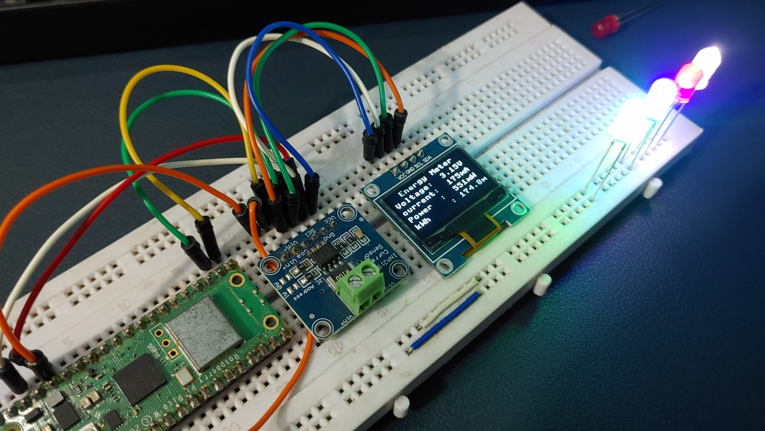
You can see as the number of LEDs increased, the values of current, voltage, and power also increased.
Then, we increased the number of LEDs to 4, resulting in a further increase in power consumption.

Conclusion
The tutorial demonstrates how to use the INA219 DC Current Sensor Module with Raspberry Pi Pico to build an Energy Meter that can measure voltage, current, and power.

