Introduction
Home automation is the process of making your home more timely, comfortable, and energy-efficient by installing and connecting devices that automate tasks and systems around your home. A Raspberry Pi Pico home automation system can do all of this and more, by connecting devices like lights, appliances, sensors, and thermostats to the Internet and controlling them remotely using a smartphone or computer.
All you need is a Raspberry Pi Pico Board, Bluetooth module, relays, wires and an android phone for control. There is a large scope of home automation applications that we can build easily by using the Raspberry Pi Pico board.
Thank You NextPCB:
This project is successfully finished because of the service and support from NextPCB. NextPCB is one of the most professional PCB manufacturers in Global and has specialized in the PCB and assembly industry for over 16 years. Not only could NextPCB deliver the most creative printed circuit boards and assembly technologies in the most elevated quality standards, but the fastest delivery turnaround was also as fast as 24 hours.
Guys if you have a PCB project, please visit their website and get exciting discounts and coupons. if you sign-up using this link you will get free coupons worth $100. Checkout out NextPCB now and get amazing discounts on your first order.
- Only 0$ for 5-10pcs PCB Prototypes:https://www.nextpcb.com/PCBPrototypes
- 4-layer PCB price reduction of up to 40%: nextpcb.com/40%off
- Register and get $100 from NextPCB: Nextpcb.com/coupon
Supplies for Raspberry Pi Pico Home Automation System
Components Required
- Raspberry Pi Pico – https://amzn.to/3LgHC1s
- Bluetooth Module HC-05 – https://amzn.to/3MJOGnF
- 4 Channel Relay Module – https://amzn.to/3Mr9UWZ
- Jumper Wires – https://amzn.to/38fpnuy
- Breadboard – https://amzn.to/3OBy8jm
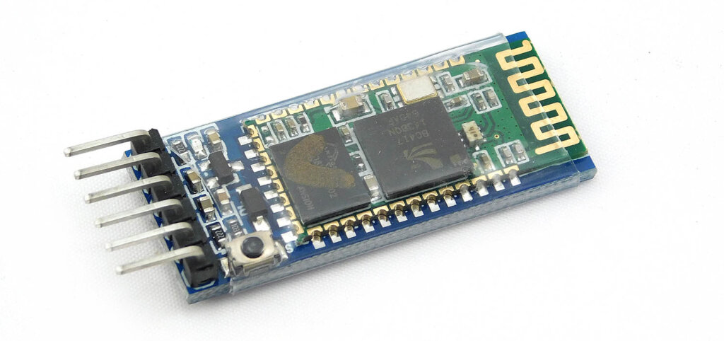
What is HC05 Module?
The HC-05 and HC-06 modules are Bluetooth modules that we can use to communicate with Raspberry Pi Pico via Bluetooth. HC-05 Bluetooth Module is one of the best ways to communicate wirelessly with the Raspberry Pi Pico. For example, we can use it to control a LED Or Relay from a mobile or tablet.
HC-05 Pinout
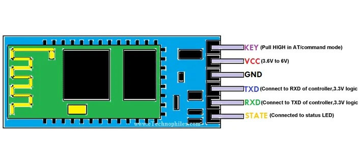
- Enable / Key: This pin is used to toggle between Data Mode (set low) and AT command mode (set high). By default, it is in Data mode
- VCC: To give power or current to the module, Connect to +5V Supply voltage or 3.3V pin.
- GND: Connect to system ground(-).
- TXD: Transmit Serial data. It is used to wirelessly receive data by the Bluetooth module.
- RDX: Receive Serial data. When the Bluetooth module transmits data, the RDX pin is used to receive that data.
- State: The state pin is connected to the onboard LED, It tells whether the module is connected or not Bluetooth and is used as feedback to check if Bluetooth is working properly.
What is Raspberry Pi Pico?
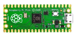
But don’t let the low price fool you, the Pico is a powerful little board. It features a Cortex M0+ CPU, 266MHz clock speed, 512KB of on-board flash storage, and 20 GPIO pins.
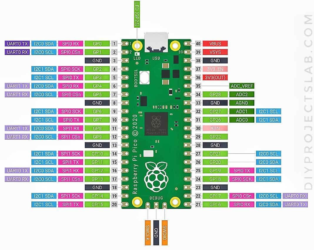
Raspberry Pi Pico Pinout
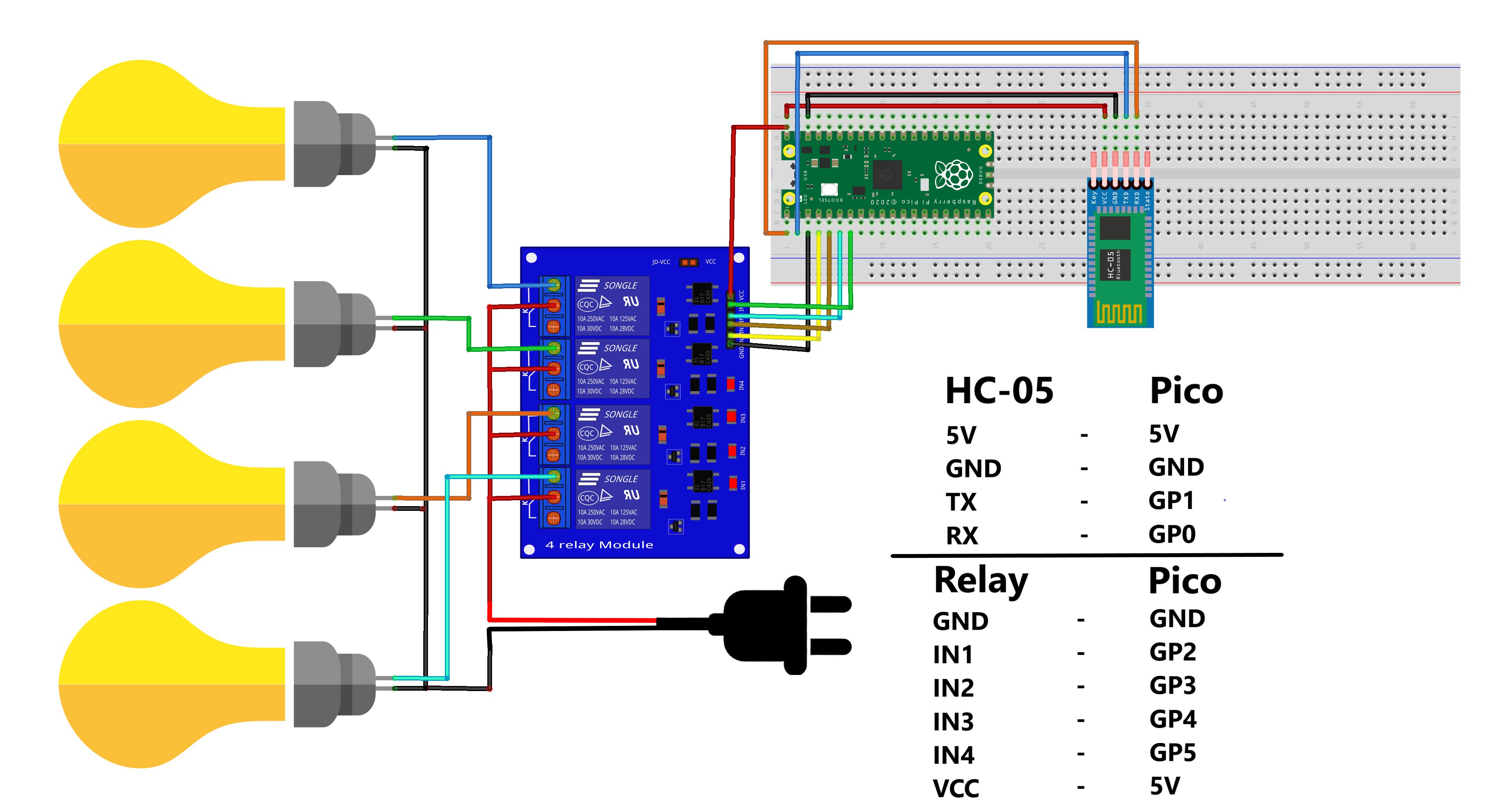
Schematics Diagram – Raspberry Pi Pico Home Automation System
The Circuit diagram is very straightforward. You have to connect the HC-05 Bluetooth module and Relay pins with Raspberry Pi Pico pins as per the schematic diagram. The schematic diagram is shown above. You may also follow the following pin mapping
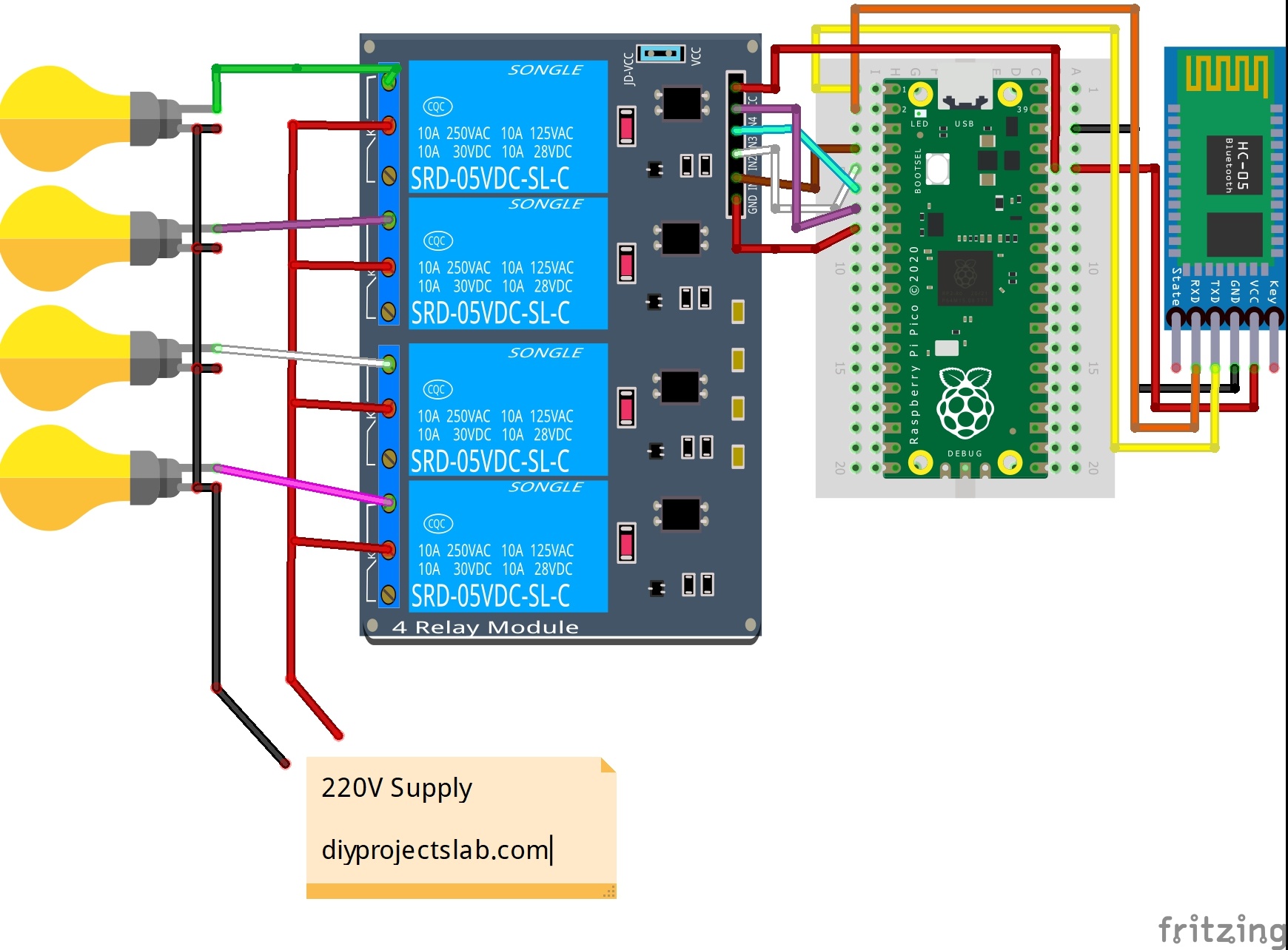
Hc-05->Raspberry Pi Pico
- VCC -> 3.3V
- GND -> GND
- RX -> GP0
- TX -> GP1
Relay -> Raspberry Pi Pico
- GND -> GND
- IN1 -> GP2
- IN2 -> GP3
- IN3 -> GP4
- IN4 -> GP5
- VCC -> 5V
Prepare the Thonny IDE for Raspberry Pi Pico Board
Thonny is now prepared to program your Raspberry Pi Pico board.
Source Code
Download the app and full code from GitHub
main.py
|
1 2 3 4 5 6 7 8 9 10 11 12 13 14 15 16 17 18 19 20 21 22 23 24 25 26 27 28 29 30 31 32 |
from machine import UART, Pin bt = UART(0,9600) L1 = Pin(2,Pin.OUT) L2 = Pin(3,Pin.OUT) L3 = Pin(4,Pin.OUT) L4 = Pin(5,Pin.OUT) while True: br = bt.readline() if "ON1" in br: L1.value(0) elif "OFF1" in br: L1.value(1) elif "ON2" in br: L2.value(0) elif "OFF2" in br: L2.value(1) elif "ON3" in br: L3.value(0) elif "OFF3" in br: L3.value(1) elif "ON4" in br: L4.value(0) elif "OFF4" in br: L4.value(1) |
Download Android App.
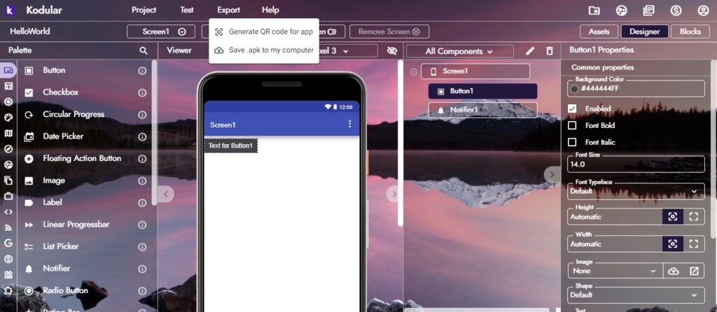
Now, Let’s make a mobile application, To make a mobile app I used kodular.
Final Working
Now, give power to the circuit and open the app, connect Bluetooth and control your lights or Fan using your smartphone.
Read Similar Articles:
- Getting Started Raspberry Pi Pico – Pinout, Specs – Beginner Guide
- Interfacing PIR Motion Sensor with Raspberry Pi Pico
- Raspberry Pi Pico Home Automation System
- Interface Servo Motor With Raspberry Pi Pico
- Interface 0.96″ OLED Display with Raspberry Pi Pico
- Raspberry Pi Pico Weather Station Using Dht11 Sensor
- Interface 16*2 LCD Display With Raspberry Pi Pico

6 Comments
Pingback: Interface 0.96" OLED Display with Raspberry Pi Pico -Explain
Pingback: Interfacing PIR Motion Sensor with Raspberry Pi Pico Using Micropython
Pingback: Getting Started With Raspberry Pi Pico With Thonny IDE
Pingback: RGB LED Using A Raspberry Pi Pico With MicroPython
Pingback: Interface Servo Motor With Raspberry Pi Pico Tutorial 2022
Pingback: Raspberry Pi Pico ADC | Read Analog Values With Micropython