Introduction
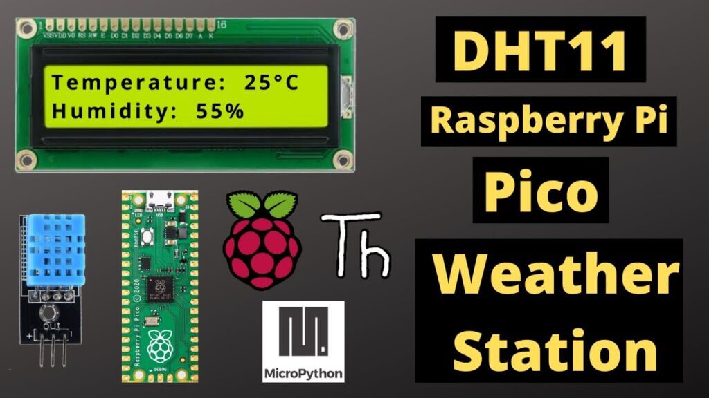
In this tutorial we will learn How to make Raspberry Pi Pico Weather Station using Dht11 Humidity Sensor, a weather station to monitor the temperature and humidity in your home or office We will use a 16×2 LCD Display and display the DHT11 temperature and Humidity value on it.
Raspberry Pi Pico Weather Station
The DHT11 Sensor is a cheap cost digital temperature and humidity sensor. we used the Raspberry Pi Pico board to read the temperature and humidity data of the Dht11 Sensor. The data is displayed on a 16×2 LCD screen.
Materials Required
Raspberry Pi Pico
The Raspberry Pi Pico is a tiny, yet powerful microcontroller that was released in January 2021. It is based on the RP2040 chip and is designed to be used with the Raspberry Pi. The Pico is a great microcontroller for beginners and professional engineers alike. It is very affordable and straightforward to use, yet still has a lot of features that more developed users will appreciate.
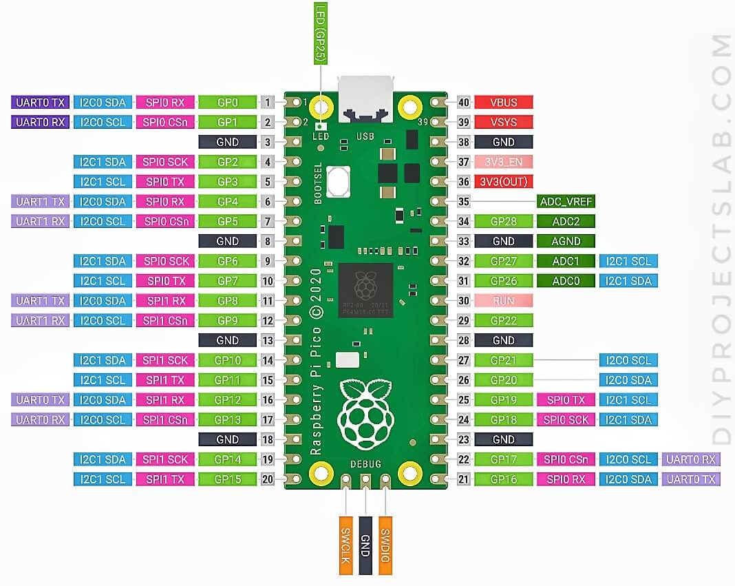
Raspberry pi pico Pinout
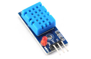
What is the dht11 Sensor?
DHT11 sensor is a temperature and humidity sensor which is used in different applications like weather forecasting, etc. It consists of a sensing part and an NTC temperature sensor. The DHT11 sensor can measure the temperature and humidity of the air in the range of 0-50°C and 20-90% RH respectively.
Specification:
- Dimensions 13 x 29 x 8 mm
- 3.3 – 5.5V power supply
- Average power consumption 0.2 mA
- Communication: 1-Wire (OneWire)
- Temperature measurement: * Temperature measurement range 0 – 50 ° C * 8-bit resolution (1 ° C) * Accuracy 1 ° C * Response time 6 – 15 s (typically 10 s)
- Moisture measurement * Humidity measurement range 20% – 90% RH (at 25 ° C) – in the full temperature range – 30% -80% * 8-bit resolution (± 1% RH *) * Accuracy ± 4 RH * (at 25 ° C) * Measuring range 6 – 30 s * Stability ± 1% RH / year
Schematics for Raspberry Pi Pico Weather Station
The hardware setup and Mapping guide for the DHT11 Sensor with Raspberry Pi Pico board & 16×2 LCD is super easy. The connection diagram is given Below.
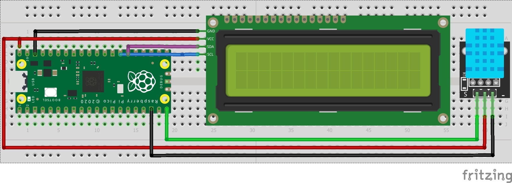
LCD -> Pico
- GND -> GND
- VCC -> VBUS(SV)
- SDA -> GP26
- SCL -> GP27
DHT11 -> Pico
- Vcc(+) -> 3.3V
- Out(o) -> GP15
- GND(-) -> GND
Source Code for Raspberry Pi Pico Weather Station
The code comprises 4 parts:
- dht.py
- lcd_api.py
- pico_i2c_lcd.py
- main.py
dht.py
Firstly you need to create a new file in Thonny IDE. Copy the following code & save the file by the name dht.py on Raspberry Pi Pico Board.
|
1 2 3 4 5 6 7 8 9 10 11 12 13 14 15 16 17 18 19 20 21 22 23 24 25 26 27 28 29 30 31 32 33 34 35 36 37 38 39 40 41 42 43 44 45 46 47 48 49 50 51 52 53 54 55 56 57 58 59 60 61 62 63 64 65 66 67 68 69 70 71 72 73 74 75 76 77 78 79 80 81 82 83 84 85 86 87 88 89 90 91 92 93 94 95 96 97 98 99 100 101 102 103 104 105 106 107 108 109 110 111 112 113 114 115 116 117 118 119 120 121 122 123 124 125 126 127 128 |
import array import micropython import utime from machine import Pin from micropython import const class InvalidChecksum(Exception): pass class InvalidPulseCount(Exception): pass MAX_UNCHANGED = const(100) MIN_INTERVAL_US = const(200000) HIGH_LEVEL = const(50) EXPECTED_PULSES = const(84) class DHT11: _temperature: int _humidity: int def __init__(self, pin): self._pin = pin self._last_measure = utime.ticks_us() self._temperature = -1 self._humidity = -1 def measure(self): current_ticks = utime.ticks_us() if utime.ticks_diff(current_ticks, self._last_measure) < MIN_INTERVAL_US and ( self._temperature > -1 or self._humidity > -1 ): # Less than a second since last read, which is too soon according # to the datasheet return self._send_init_signal() pulses = self._capture_pulses() buffer = self._convert_pulses_to_buffer(pulses) self._verify_checksum(buffer) self._humidity = buffer[0] + buffer[1] / 10 self._temperature = buffer[2] + buffer[3] / 10 self._last_measure = utime.ticks_us() @property def humidity(self): self.measure() return self._humidity @property def temperature(self): self.measure() return self._temperature def _send_init_signal(self): self._pin.init(Pin.OUT, Pin.PULL_DOWN) self._pin.value(1) utime.sleep_ms(50) self._pin.value(0) utime.sleep_ms(18) @micropython.native def _capture_pulses(self): pin = self._pin pin.init(Pin.IN, Pin.PULL_UP) val = 1 idx = 0 transitions = bytearray(EXPECTED_PULSES) unchanged = 0 timestamp = utime.ticks_us() while unchanged < MAX_UNCHANGED: if val != pin.value(): if idx >= EXPECTED_PULSES: raise InvalidPulseCount( "Got more than {} pulses".format(EXPECTED_PULSES) ) now = utime.ticks_us() transitions[idx] = now - timestamp timestamp = now idx += 1 val = 1 - val unchanged = 0 else: unchanged += 1 pin.init(Pin.OUT, Pin.PULL_DOWN) if idx != EXPECTED_PULSES: raise InvalidPulseCount( "Expected {} but got {} pulses".format(EXPECTED_PULSES, idx) ) return transitions[4:] def _convert_pulses_to_buffer(self, pulses): """Convert a list of 80 pulses into a 5 byte buffer The resulting 5 bytes in the buffer will be: 0: Integral relative humidity data 1: Decimal relative humidity data 2: Integral temperature data 3: Decimal temperature data 4: Checksum """ # Convert the pulses to 40 bits binary = 0 for idx in range(0, len(pulses), 2): binary = binary << 1 | int(pulses[idx] > HIGH_LEVEL) # Split into 5 bytes buffer = array.array("B") for shift in range(4, -1, -1): buffer.append(binary >> shift * 8 & 0xFF) return buffer def _verify_checksum(self, buffer): # Calculate checksum checksum = 0 for buf in buffer[0:4]: checksum += buf if checksum & 0xFF != buffer[4]: raise InvalidChecksum() |
lcd_api.py
Open a new tab again in the Thonny IDE. Copy the following below code and paste it onto the Thonny IDE new tab. Save the file by the name lcd_api.py in Raspberry Pi Pico.
|
1 2 3 4 5 6 7 8 9 10 11 12 13 14 15 16 17 18 19 20 21 22 23 24 25 26 27 28 29 30 31 32 33 34 35 36 37 38 39 40 41 42 43 44 45 46 47 48 49 50 51 52 53 54 55 56 57 58 59 60 61 62 63 64 65 66 67 68 69 70 71 72 73 74 75 76 77 78 79 80 81 82 83 84 85 86 87 88 89 90 91 92 93 94 95 96 97 98 99 100 101 102 103 104 105 106 107 108 109 110 111 112 113 114 115 116 117 118 119 120 121 122 123 124 125 126 127 128 129 130 131 132 133 134 135 136 137 138 139 140 141 142 143 144 145 146 147 148 149 150 151 152 153 154 155 156 157 158 159 160 161 162 163 164 165 166 167 168 169 170 171 172 173 174 175 176 177 178 179 180 181 182 183 184 185 186 187 188 189 190 191 192 193 194 195 |
"""Provides an API for talking to HD44780 compatible character LCDs.""" import time class LcdApi: """Implements the API for talking with HD44780 compatible character LCDs. This class only knows what commands to send to the LCD, and not how to get them to the LCD. It is expected that a derived class will implement the hal_xxx functions. """ # The following constant names were lifted from the avrlib lcd.h # header file, however, I changed the definitions from bit numbers # to bit masks. # # HD44780 LCD controller command set LCD_CLR = 0x01 # DB0: clear display LCD_HOME = 0x02 # DB1: return to home position LCD_ENTRY_MODE = 0x04 # DB2: set entry mode LCD_ENTRY_INC = 0x02 # --DB1: increment LCD_ENTRY_SHIFT = 0x01 # --DB0: shift LCD_ON_CTRL = 0x08 # DB3: turn lcd/cursor on LCD_ON_DISPLAY = 0x04 # --DB2: turn display on LCD_ON_CURSOR = 0x02 # --DB1: turn cursor on LCD_ON_BLINK = 0x01 # --DB0: blinking cursor LCD_MOVE = 0x10 # DB4: move cursor/display LCD_MOVE_DISP = 0x08 # --DB3: move display (0-> move cursor) LCD_MOVE_RIGHT = 0x04 # --DB2: move right (0-> left) LCD_FUNCTION = 0x20 # DB5: function set LCD_FUNCTION_8BIT = 0x10 # --DB4: set 8BIT mode (0->4BIT mode) LCD_FUNCTION_2LINES = 0x08 # --DB3: two lines (0->one line) LCD_FUNCTION_10DOTS = 0x04 # --DB2: 5x10 font (0->5x7 font) LCD_FUNCTION_RESET = 0x30 # See "Initializing by Instruction" section LCD_CGRAM = 0x40 # DB6: set CG RAM address LCD_DDRAM = 0x80 # DB7: set DD RAM address LCD_RS_CMD = 0 LCD_RS_DATA = 1 LCD_RW_WRITE = 0 LCD_RW_READ = 1 def __init__(self, num_lines, num_columns): self.num_lines = num_lines if self.num_lines > 4: self.num_lines = 4 self.num_columns = num_columns if self.num_columns > 40: self.num_columns = 40 self.cursor_x = 0 self.cursor_y = 0 self.backlight = True self.display_off() self.backlight_on() self.clear() self.hal_write_command(self.LCD_ENTRY_MODE | self.LCD_ENTRY_INC) self.hide_cursor() self.display_on() def clear(self): """Clears the LCD display and moves the cursor to the top left corner. """ self.hal_write_command(self.LCD_CLR) self.hal_write_command(self.LCD_HOME) self.cursor_x = 0 self.cursor_y = 0 def show_cursor(self): """Causes the cursor to be made visible.""" self.hal_write_command(self.LCD_ON_CTRL | self.LCD_ON_DISPLAY | self.LCD_ON_CURSOR) def hide_cursor(self): """Causes the cursor to be hidden.""" self.hal_write_command(self.LCD_ON_CTRL | self.LCD_ON_DISPLAY) def blink_cursor_on(self): """Turns on the cursor, and makes it blink.""" self.hal_write_command(self.LCD_ON_CTRL | self.LCD_ON_DISPLAY | self.LCD_ON_CURSOR | self.LCD_ON_BLINK) def blink_cursor_off(self): """Turns on the cursor, and makes it no blink (i.e. be solid).""" self.hal_write_command(self.LCD_ON_CTRL | self.LCD_ON_DISPLAY | self.LCD_ON_CURSOR) def display_on(self): """Turns on (i.e. unblanks) the LCD.""" self.hal_write_command(self.LCD_ON_CTRL | self.LCD_ON_DISPLAY) def display_off(self): """Turns off (i.e. blanks) the LCD.""" self.hal_write_command(self.LCD_ON_CTRL) def backlight_on(self): """Turns the backlight on. This isn't really an LCD command, but some modules have backlight controls, so this allows the hal to pass through the command. """ self.backlight = True self.hal_backlight_on() def backlight_off(self): """Turns the backlight off. This isn't really an LCD command, but some modules have backlight controls, so this allows the hal to pass through the command. """ self.backlight = False self.hal_backlight_off() def move_to(self, cursor_x, cursor_y): """Moves the cursor position to the indicated position. The cursor position is zero based (i.e. cursor_x == 0 indicates first column). """ self.cursor_x = cursor_x self.cursor_y = cursor_y addr = cursor_x & 0x3f if cursor_y & 1: addr += 0x40 # Lines 1 & 3 add 0x40 if cursor_y & 2: addr += 0x14 # Lines 2 & 3 add 0x14 self.hal_write_command(self.LCD_DDRAM | addr) def putchar(self, char): """Writes the indicated character to the LCD at the current cursor position, and advances the cursor by one position. """ if char != '\n': self.hal_write_data(ord(char)) self.cursor_x += 1 if self.cursor_x >= self.num_columns or char == '\n': self.cursor_x = 0 self.cursor_y += 1 if self.cursor_y >= self.num_lines: self.cursor_y = 0 self.move_to(self.cursor_x, self.cursor_y) def putstr(self, string): """Write the indicated string to the LCD at the current cursor position and advances the cursor position appropriately. """ for char in string: self.putchar(char) def custom_char(self, location, charmap): """Write a character to one of the 8 CGRAM locations, available as chr(0) through chr(7). """ location &= 0x7 self.hal_write_command(self.LCD_CGRAM | (location << 3)) time.sleep_us(40) for i in range(8): self.hal_write_data(charmap[i]) time.sleep_us(40) self.move_to(self.cursor_x, self.cursor_y) def hal_backlight_on(self): """Allows the hal layer to turn the backlight on. If desired, a derived HAL class will implement this function. """ pass def hal_backlight_off(self): """Allows the hal layer to turn the backlight off. If desired, a derived HAL class will implement this function. """ pass def hal_write_command(self, cmd): """Write a command to the LCD. It is expected that a derived HAL class will implement this function. """ raise NotImplementedError def hal_write_data(self, data): """Write data to the LCD. It is expected that a derived HAL class will implement this function. """ raise NotImplementedError |
i2c_lcd.py
Open a new tab again in the Thonny IDE. Copy the following below code and paste it onto the Thonny IDE new tab. Save the file by the name i2c_lcd.py in Raspberry Pi Pico.
|
1 2 3 4 5 6 7 8 9 10 11 12 13 14 15 16 17 18 19 20 21 22 23 24 25 26 27 28 29 30 31 32 33 34 35 36 37 38 39 40 41 42 43 44 45 46 47 48 49 50 51 52 53 54 55 56 57 58 59 60 61 62 63 64 65 66 67 68 69 70 71 72 73 74 75 76 77 78 79 80 |
from lcd_api import LcdApi from machine import I2C from time import sleep_ms # The PCF8574 has a jumper selectable address: 0x20 - 0x27 DEFAULT_I2C_ADDR = 0x27 # Defines shifts or masks for the various LCD line attached to the PCF8574 MASK_RS = 0x01 MASK_RW = 0x02 MASK_E = 0x04 SHIFT_BACKLIGHT = 3 SHIFT_DATA = 4 class I2cLcd(LcdApi): """Implements a HD44780 character LCD connected via PCF8574 on I2C.""" def __init__(self, i2c, i2c_addr, num_lines, num_columns): self.i2c = i2c self.i2c_addr = i2c_addr self.i2c.writeto(self.i2c_addr, bytearray([0])) sleep_ms(20) # Allow LCD time to powerup # Send reset 3 times self.hal_write_init_nibble(self.LCD_FUNCTION_RESET) sleep_ms(5) # need to delay at least 4.1 msec self.hal_write_init_nibble(self.LCD_FUNCTION_RESET) sleep_ms(1) self.hal_write_init_nibble(self.LCD_FUNCTION_RESET) sleep_ms(1) # Put LCD into 4 bit mode self.hal_write_init_nibble(self.LCD_FUNCTION) sleep_ms(1) LcdApi.__init__(self, num_lines, num_columns) cmd = self.LCD_FUNCTION if num_lines > 1: cmd |= self.LCD_FUNCTION_2LINES self.hal_write_command(cmd) def hal_write_init_nibble(self, nibble): """Writes an initialization nibble to the LCD. This particular function is only used during initialization. """ byte = ((nibble >> 4) & 0x0f) << SHIFT_DATA self.i2c.writeto(self.i2c_addr, bytearray([byte | MASK_E])) self.i2c.writeto(self.i2c_addr, bytearray([byte])) def hal_backlight_on(self): """Allows the hal layer to turn the backlight on.""" self.i2c.writeto(self.i2c_addr, bytearray([1 << SHIFT_BACKLIGHT])) def hal_backlight_off(self): """Allows the hal layer to turn the backlight off.""" self.i2c.writeto(self.i2c_addr, bytearray([0])) def hal_write_command(self, cmd): """Writes a command to the LCD. Data is latched on the falling edge of E. """ byte = ((self.backlight << SHIFT_BACKLIGHT) | (((cmd >> 4) & 0x0f) << SHIFT_DATA)) self.i2c.writeto(self.i2c_addr, bytearray([byte | MASK_E])) self.i2c.writeto(self.i2c_addr, bytearray([byte])) byte = ((self.backlight << SHIFT_BACKLIGHT) | ((cmd & 0x0f) << SHIFT_DATA)) self.i2c.writeto(self.i2c_addr, bytearray([byte | MASK_E])) self.i2c.writeto(self.i2c_addr, bytearray([byte])) if cmd <= 3: # The home and clear commands require a worst case delay of 4.1 msec sleep_ms(5) def hal_write_data(self, data): """Write data to the LCD.""" byte = (MASK_RS | (self.backlight << SHIFT_BACKLIGHT) | (((data >> 4) & 0x0f) << SHIFT_DATA)) self.i2c.writeto(self.i2c_addr, bytearray([byte | MASK_E])) self.i2c.writeto(self.i2c_addr, bytearray([byte])) byte = (MASK_RS | (self.backlight << SHIFT_BACKLIGHT) | ((data & 0x0f) << SHIFT_DATA)) self.i2c.writeto(self.i2c_addr, bytearray([byte | MASK_E])) self.i2c.writeto(self.i2c_addr, bytearray([byte])) |
main.py
and finally, Open a new tab again in the Thonny IDE. Copy the following below code and paste it onto the Thonny IDE new tab. Save the file by the name main.py in Raspberry Pi Pico.
|
1 2 3 4 5 6 7 8 9 10 11 12 13 14 15 16 17 18 19 20 21 22 23 24 25 26 27 28 29 30 31 32 33 34 35 36 37 38 39 40 |
from machine import I2C, Pin from i2c_lcd import I2cLcd from utime import sleep from dht import DHT11, InvalidChecksum DEFAULT_I2C_ADDR = 0x27 # LCD 1602 I2C address led_red = Pin(4,Pin.OUT) led_green = Pin(5,Pin.OUT) pin = Pin(2, Pin.OUT, Pin.PULL_DOWN) dht11 = DHT11(pin) def setup(): global lcd i2c = I2C(0,sda=Pin(0),scl=Pin(1),freq=400000) lcd = I2cLcd(i2c, DEFAULT_I2C_ADDR, 2, 16) # Initialize(device address, cursor settings) def loop(): try: while True: lcd.move_to(0,0) lcd.putstr("Temperature: {}".format(dht11.temperature)) lcd.move_to(0,1) lcd.putstr("Humidity: {}".format(dht11.humidity)) if dht11.temperature > 35 or dht11.humidity < 10: led_red.value(1) led_green.value(0) sleep(0.5) led_red.value(0) sleep(0.5) else: led_red.value(0) led_green.value(1) sleep(1) lcd.clear() except InvalidChecksum: print("Checksum from the sensor was invalid") if __name__ == '__main__': setup() loop() |
Conclusion
After the Upload code, You will see that the Pico board Start displaying the weather temp. on Display.
Read Similar Articles:
- Getting Started Raspberry Pi Pico – Pinout, Specs – Beginner Guide
- Interfacing PIR Motion Sensor with Raspberry Pi Pico
- Raspberry Pi Pico Home Automation System
- Interface Servo Motor With Raspberry Pi Pico
- Interface 0.96″ OLED Display with Raspberry Pi Pico
- Raspberry Pi Pico Weather Station Using Dht11 Sensor
- Interface 16*2 LCD Display With Raspberry Pi Pico

2 Comments
Pingback: Interface Servo Motor With Raspberry Pi Pico - Explain 2022
Pingback: Raspberry Pi With Ultrasonic Sensor Tutorial 2022